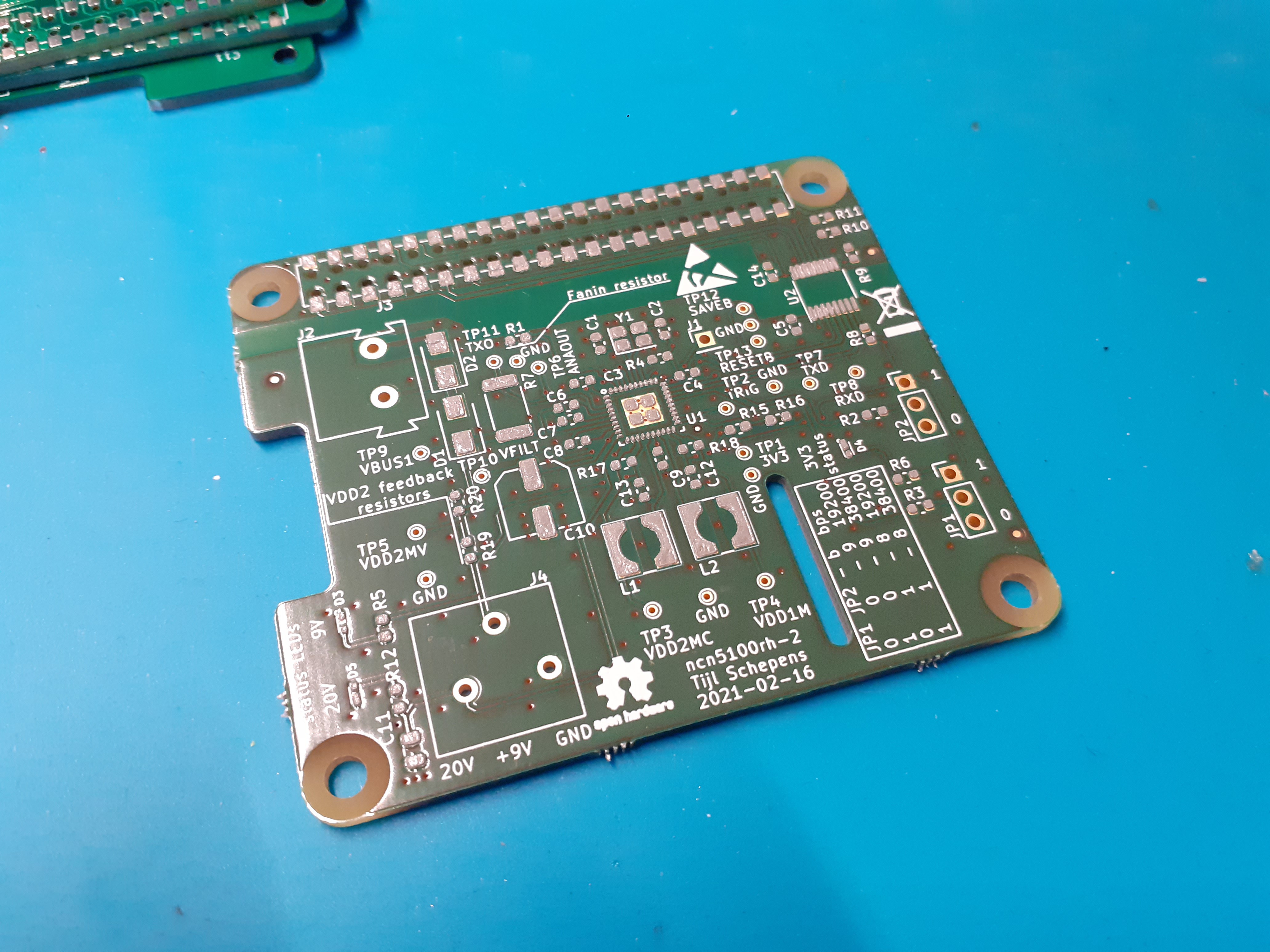
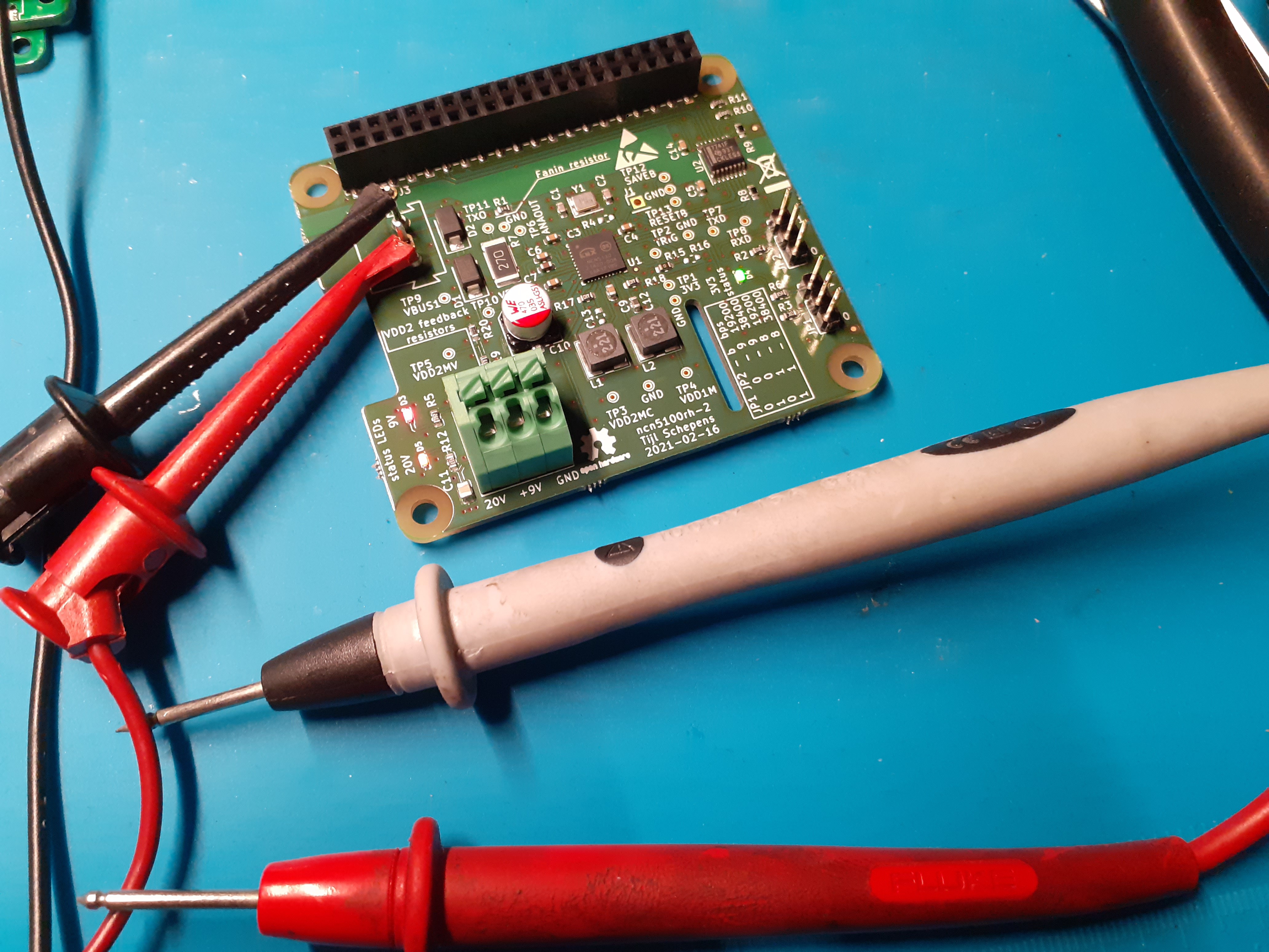
Today I started soldering the new PCB. I started of with one as a prototype.

While placing the components I saw that I made a mistake. For the VDD2 regulator I selected a 10 uF 6.3 V capacitor. But the regulator is configured for 9 V. On the previous design I made the same mistake but never spotted it. So the ceramic capacitor on ncn5100rh-1 is probably toast now...
I'll have to look into ordering a 25 V variant. There are many available on Mouser.

So for the time being I did not solder C13. After powering up the VDD2 regulator is not working, but this is quite logical as the capacitor is not present... The 20 V regulator and the 3.3 V are present and operational! The TXD line on the transceiver side is high which is good!
Now it's time to hook it up to a Raspberry Pi and see what happens.
 Tijl Schepens
Discussions
Become a Hackaday.io Member
Create an account to leave a comment. Already have an account? Log In.