Of course, I disassembled the Lidar module to better understand how it works.
First, after removing the PCB, the underside of the laser; We see the two blue wires going to the center, and we see what looks to be an IR diode and receiver in the middle.

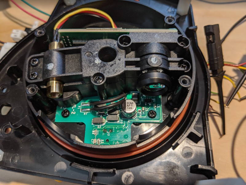
Then if we remove the top cover housing, we see the actual laser (left) and a camera (right) receiver.

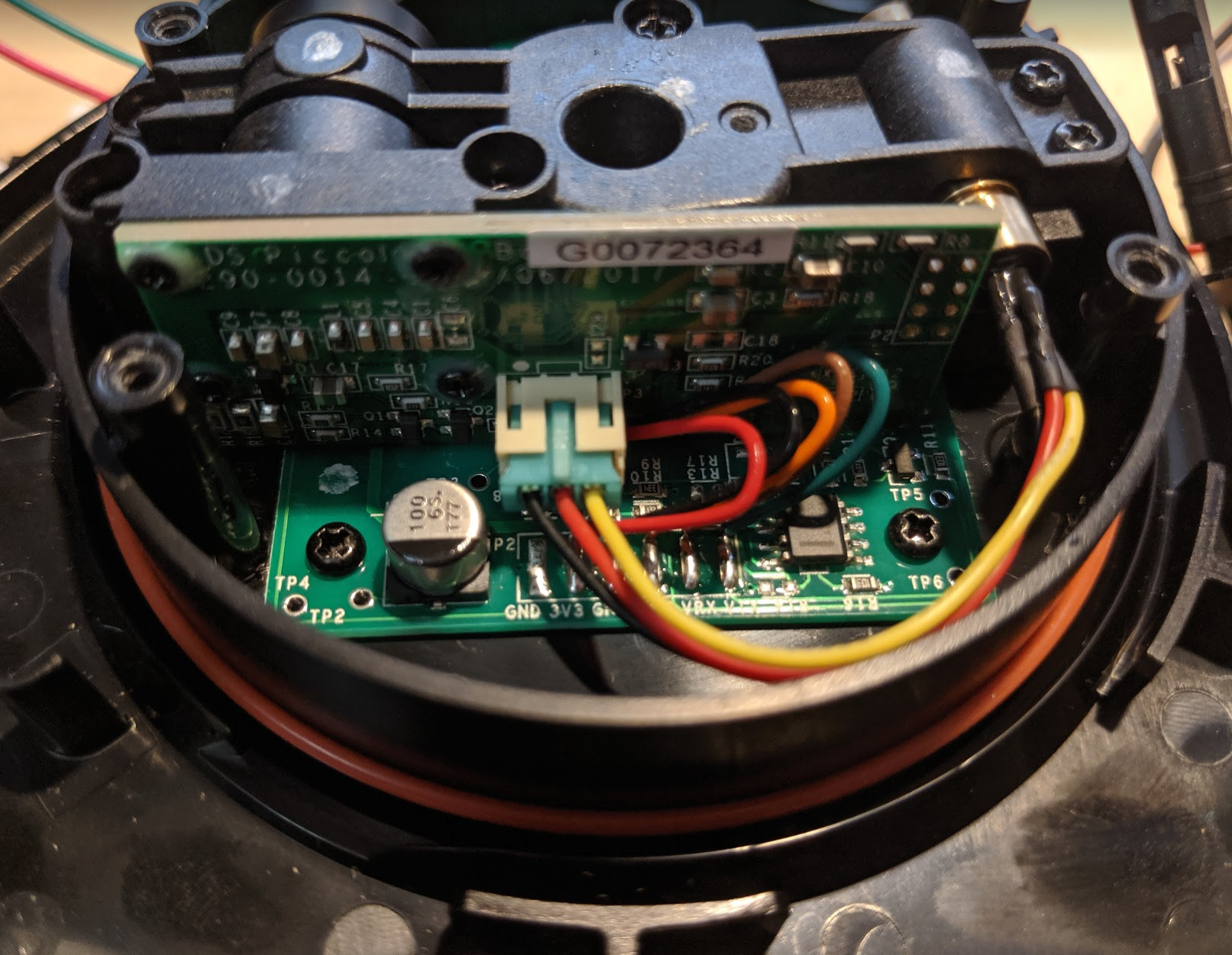
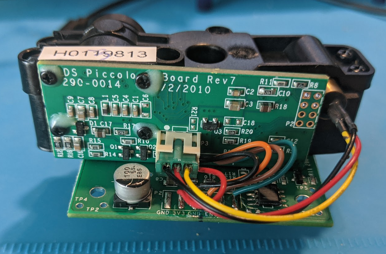
And from the other side, we see GND, 3v3, GND, ENC, VRX, VTX pins (some hidden in the picture, but that's what's there)

We can easily remove the electronics from the rotating portion:

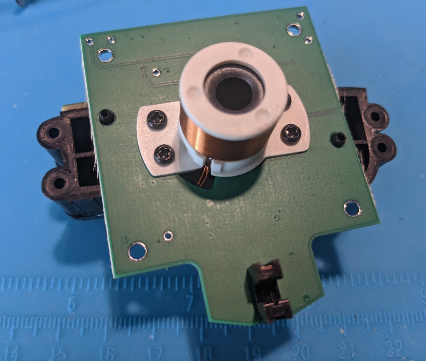
And the underside of the above shows a two-wire inductor! We also see (at bottom of image) the method by which the rotation rate is determined: an IR encoder. Not included in my pictures is that there are (iirc) 5 cutouts over which the IR encoder passes per revolution.

I'm not an electrical engineer, but I've seen enough things to say the following (apologies for inaccuracies in technical jargon, etc.):
- The electronics shown above are powered via this inductor. Inductors, like e.g. Qi chargers, use AC. The fact that the coils rotate relative to each other doesn't matter here; power is induced in the above coil whether the laser is spinning or not. In comparison, some subset of electric motors will have multiple winding groups, aka poles, and alternating/phasing the AC power to these poles induces magnetic field changes, which move the coils relative to a permanent magnet.
- The large PCB removed before the first step takes an input DC voltage, and converts it to presumably AC (I don't have an oscilloscope, but I did see the alternating waveforms with a logic analyzer)
Looks like I neglected to take a picture showing the corresponding fixed coil of the inductance setup.
 Gertlex
Discussions
Become a Hackaday.io Member
Create an account to leave a comment. Already have an account? Log In.