Close
0%
0%

Neato D-Series Lidar and Raspberry Pi 3A+ with ROS

Working towards an autonomous mech warfare robot. (2020)

Similar projects worth following
NOTE: This project is from 2020, and ran into enough challenges that I abandoned it. I have since bought a LD-AIR Lidar, which is smaller.

My long-term goal is to play with partial autonomy with my Mech Warfare robot, Numa 2. I'm not trying to massively increase the cost of that project, so a key objective is to use reasonably cheap and minimal hardware. Also, the space available on a mech is pretty limited, due to a large number of components already.

With that in mind, my hardware selection for additions to Numa 2 are the following:
- Raspberry Pi 3A+
- Neato lidar to be mounted on underside of mech
- Motor driver to send adjustable voltage to the Lidar

Raspberry Pi Configuration

Because the 3A+ is not anyone's definition of powerful, I want to make sure that its not running anything more than it needs to be.  First item on the list of unnecessary things is the graphical desktop!

To configure the RPi to be "headless", the procedure was approximately the following:

  1. Install Ubiquiti's ROS Kinetic/Ubuntu Xenial image from here. I used 2019-06-19 release, but it looks like newer ones are available now.
  2. Upon initial boot, I was able to log in, though it was slow.  I quickly went to a TTY by pressing ctrl+alt+F1.
  3. The following commands were done to disable the desktop and reboot the device:
    sudo su
    systemctl set-default multi-user.target --force
    systemctl disable lightdm --force
    systemctl disable magni-base    # This is a ROS launching thing for a robot named magni. Doing my own instead...
    reboo
  4. Next, I got wifi set up using `nmcli`, which I already have extensive familiarity with:

    sudo su   # This command may take several **minutes** to complete. Patience...
    cd /etc/NetworkManager/system-connections
    rm *  # This removes the default behavior of acting as an access point you can connect to
    service network-manager restart
    nmcli d wifi rescan
    nmcli d wifi  # should see list of networks, if not retry the previous command
    nmcli d wifi connect YOURSSID password YOURPASSWORD
    ping google.com # yay!
  5. And I have a few utilties that I always want on an Ubuntu system:

    # Also, you do need to run apt update before you can install packages...
    apt update
    apt install byobu lm-sensors silversearcher-ag vim-gtk -y
    apt upgrade
    
    df -h /  # for me, about 4GB is used. I'm using a 16GB uSD card, so plenty of space.
  6. I next used `sudo raspi-config` to explore my options, and change the password from the default.

At this point, the raspberry Pi was configured enough for the experimentation I wanted to start with.

View all 7 components

  • Final result / Post-mortem

    Gertlex10/14/2023 at 05:51 0 comments

    tl;dr: My final conclusion with this project was that I got it to work, but there appeared to be still more hardware issues, and I stopped working on it further...

    After getting the laser spinning, I was able to read the output of the laser hardware.  I found that I was continually getting start-up information (e.g. the sensor type/version... Piccolo something).  Ultimately, I think it was in a restart loop due to power issues.

    Based on various clues (and conversation with former Neato employees), I realized the laser was getting its power via induction, and ultimately creating regular DC voltage for the electronics.

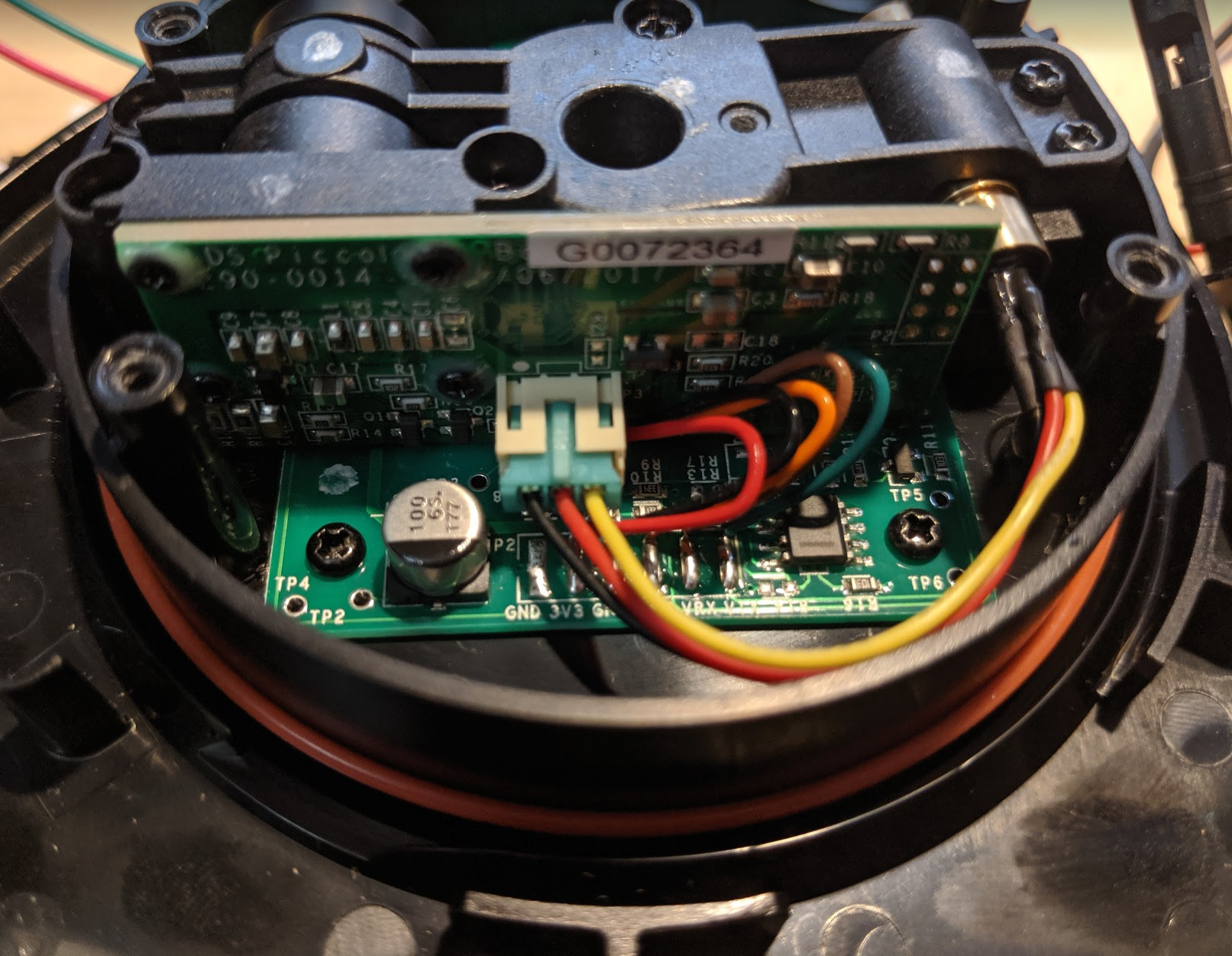
    As a total hack, after figuring out some of the pins on the electronics within the spinning laser, I decided to try directly powering it with a battery, and this worked! I used the old Intel Edison battery board (red board in pictures), which holds a single ~3.7V LiPo.  I added a power button PCB from Pololu to be able to turn power on/off.

    With that, I very quickly got the laser data to stream, and could view the published data with RViz successfully, but the data eventually deteriorated and stopped publishing.  I reproduced this a few times, concluded additional hardware issues, and never returned to the project.

    I still considered it relatively successful!

  • Tangent: popular boards hate UART

    Gertlex06/15/2020 at 04:38 1 comment

    I've probably mentioned this already, but just in case: my intention is to have the pyboard talking to the raspberry pi, and the raspberry pi listening to the lidar. But unfortunately for me, the raspberry pi only breaks out one hardware serial port to it's 40-odd pins! Lame.

    For the record, this is why I never did anything with Arduino boards: they too have a single serial port, generally (or the second one uses the USB port... which I'd like to use for programming a given robot).  I guess the Raspberry Pi guys continue that tradition; perhaps it was a limitation of the original board, and maintaining backwards compatibility for RPi hats means we're stuck with that

    Historically, I've used the Axon (Atmega 640) with 3 or 4 UARTs, the wixel with 2+ UARts, and then the pyboard, with 4 or 5 UARTs.  I caved and went the popular route of using a Raspberry Pi since it's not its own entire thing (yay Linux!) like Arduino kind of was, and because I happened to be doing some stuff with RPi 3B+ boards at work.

    So, mainstream hackers are dumb and don't use UARTs enough, and the market gives us correspondingly dumb boards? Let's go with that ¯\_(ツ)_/¯. Rant over.

    So, what am I to do? Well, there's a few options... here's how I ranked them before getting started:

    1. Try out "software" serial port options for the RPis
    2. Find a different "knockoff" RPi-like board that's better suited for my needs
    3. Finally heed a few people that have asked, regarding board-to-board communications, "why not just use I2C or SPI?" in the past, and learn something new... Nahhh.

    So I dove into the software serial options.

    First, there is a second UART on the Raspberry Pi boards, and by default it's used in conjunction with the onboard Bluetooth.  Pyboard doesn't have Bluetooth, and I like to avoid wireless whenever I can, especially in the RF-heavy environments we tend to do Mech Warfare in.

    After a few hours of reading, I finally concluded that you can't just map this extra serial hardware to a set of the GPIO pins.  I'm not EE, but I want to believe the Raspberry Pi folks could have easily done this, but didn't. (I'm probably wrong... there is lots that I do not know.)

    Somehow or the other, I ran across PiGPIO: http://abyz.me.uk/rpi/pigpio/index.html

    It comes already installed with the Ubiquity Robotics image, with a daemon ready to run, too: pigpiod.

    And lo, I was able to get this to work in quick prototyping.  But then I ran into a wall: To work with the XV11 ROS 1 package's node, my serial data has to be on a /dev/ttyXXX interface.  As best I can tell, there is no plug and play approach to doing this with pigpio.  There is /dev/pigpio, but it doesn't act like a TTY Serial port, not too surprisingly.

    So... a quickly dug up option is the RockPi S board, which is pretty comparable to the Raspberry Pi 3A+.  It has 3 UARTs.  It doesn't have HDMI, which is interesting.  Sounds like an adventure!  Here's a comparison of the two boards: https://www.hackerboards.com/compare/359,301/ (I suspect that the RockPi S having HDMI audio, but no HDMI port, is likely an error)

    So, I plan to eventually acquire the RockPi S, but first I should probably figure out how to make the laser reliable in continuous operation.

  • Reading Laser Data Take 1

    Gertlex06/15/2020 at 04:15 0 comments

    Todo

  • Spinning!

    Gertlex06/15/2020 at 04:15 0 comments

    TODO

  • Identifying connection points

    Gertlex06/06/2020 at 20:07 0 comments

    To connect to the laser, we need to identify what pins or test points to solder or otherwise connect wires to.  Based on hearsay, the expectation was that the same interface as the XV11 Lidars was still in place:

    • 115200 baud serial
    • 3V3 logic (?verify)
    • 5V power for the motor

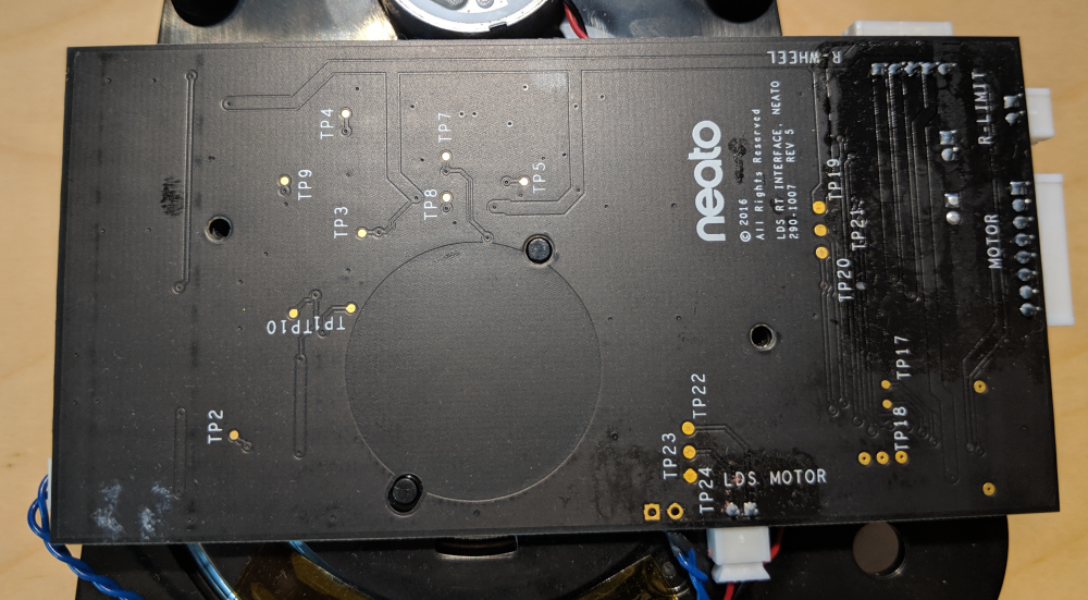
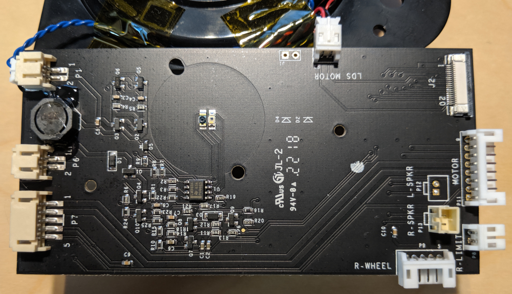
    The interface board, shown below, is also an interface for several other components on the vacuum: wheel motors, wheel encoders and speakers.

    To jump straight to results, the following were identified and relevant:
    • Motor power: LDS MOTOR connector
    • GND: TP10
    • TX: TP6
    • RX: TP7
    • VCC: TP3, TP19

    Less relevant:

    • Driving the inductor (blue wires): TP1 and TP2

  • Disassembly

    Gertlex05/24/2020 at 14:56 0 comments

    Of course, I disassembled the Lidar module to better understand how it works.

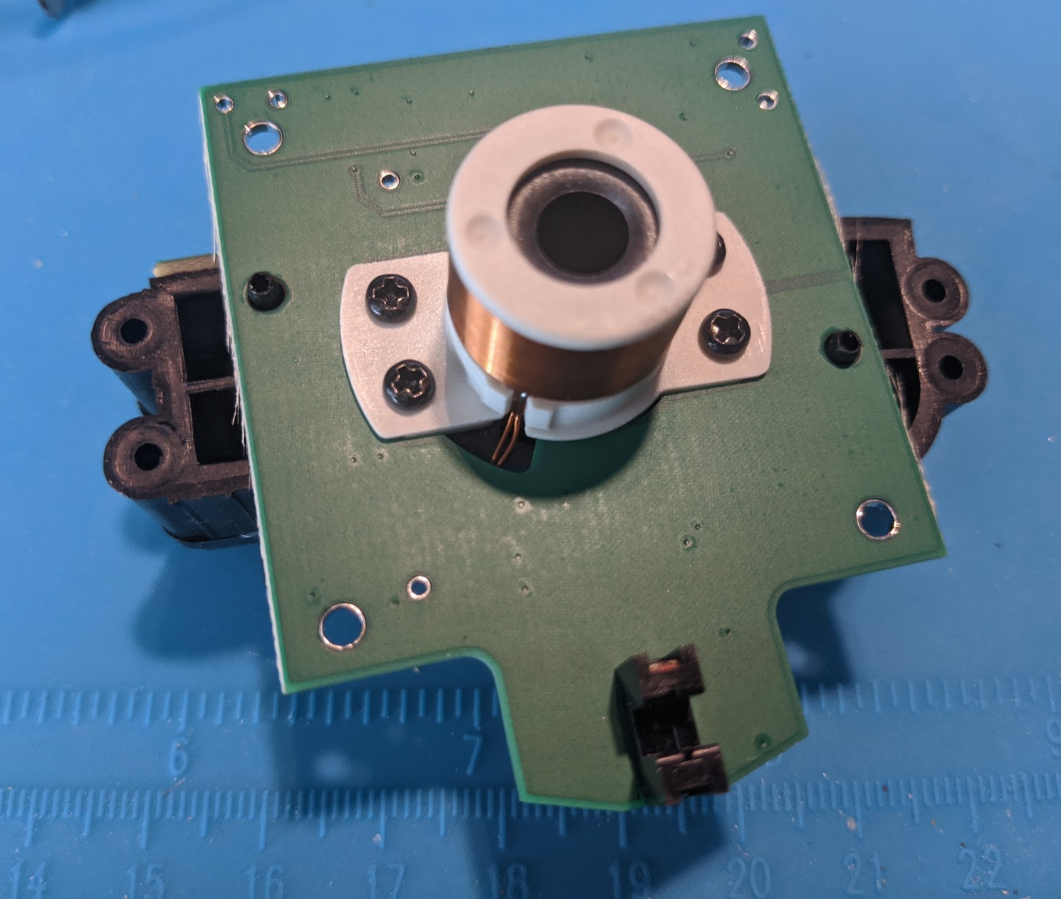
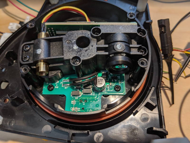
    First, after removing the PCB, the underside of the laser; We see the two blue wires going to the center, and we see what looks to be an IR diode and receiver in the middle.


    Then if we remove the top cover housing, we see the actual laser (left) and a camera (right) receiver.


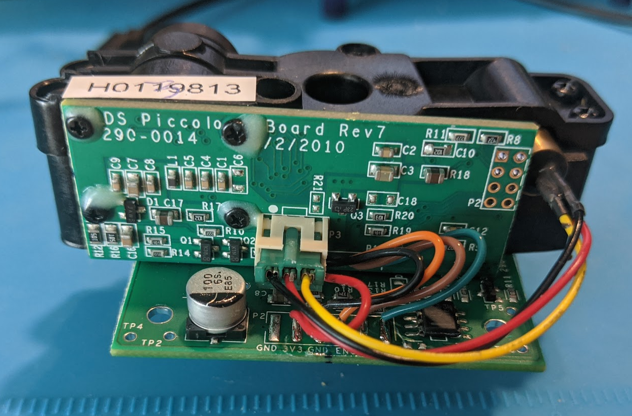
    And from the other side, we see GND, 3v3, GND, ENC, VRX, VTX pins (some hidden in the picture, but that's what's there)

    We can easily remove the electronics from the rotating portion:

    And the underside of the above shows a two-wire inductor!  We also see (at bottom of image) the method by which the rotation rate is determined: an IR encoder.  Not included in my pictures is that there are (iirc) 5 cutouts over which the IR encoder passes per revolution.

    I'm not an electrical engineer, but I've seen enough things to say the following (apologies for inaccuracies in technical jargon, etc.):
    - The electronics shown above are powered via this inductor.  Inductors, like e.g. Qi chargers, use AC.  The fact that the coils rotate relative to each other doesn't matter here; power is induced in the above coil whether the laser is spinning or not.  In comparison, some subset of electric motors will have multiple winding groups, aka poles, and alternating/phasing the AC power to these poles induces magnetic field changes, which move the coils relative to a permanent magnet.
    - The large PCB removed before the first step takes an input DC voltage, and converts it to presumably AC (I don't have an oscilloscope, but I did see the alternating waveforms with a logic analyzer)

    Looks like I neglected to take a picture showing the corresponding fixed coil of the inductance setup.

View all 6 project logs

Enjoy this project?

Share

Discussions

Similar Projects

Does this project spark your interest?

Become a member to follow this project and never miss any updates