-
Day 8
06/02/2020 at 15:48 • 0 commentsPressed print.
-
Day 7
05/31/2020 at 19:53 • 0 commentsWith the 2nd prototype in hand, it was obvious that gluing the halves together would be challenging. So wider lands were drawn and changed to captive nuts rather than threading the plastic for mounting the driver. That was a left handed bit. So after the mods, am printing a right handed side. They'll marry up well enough for a test while the printer is busy.
In other news, the Fiancee noticed what I've been getting up to and wants them for her desk. Hopefully I'll get to enjoy them a little before they're whisked away...
-
Day 6
05/30/2020 at 16:47 • 0 commentsFairly sure I've gone up a CAD belt. Certainly still one of the colours and not reached first Dan yet. Still, various cans of worms have been conquered.
Today's progress was drawing the speaker mount, front bezel and an impedance matching cone.
What is an impedance matching cone? It's a cone stuck to the back of the speaker driver's magnet assembly that allows a constant surface area of the duct to flow around the assembly and to the cone. This avoids a step change in diameter immediately behind the speaker.
The question of the resonance frequency of a tapered, spiral transmission line also raised its head. The length of the centreline is 0.61 m, and would have 1/4 wave resonance of 139 Hz. I'm aiming to go for a little lower than 175 Hz, which is the free air tuning of the driver. However, the inner, tightest path that can be taken is only 0.45 m long and would have a resonance of 189 Hz. While the outer and longest path is 0.80 m, which would resonate at 106 Hz. So which is it?
Presently printing the first half snail. Shall print the other half tomorrow and experiment once it's done. Whatever the case, it's in the right ball park and can be further lowered with dampening material. So it should "work" one way or another and might require some dampening material.
Guess I'll find out in a couple of days. Hurrah for 3D printer noises!
-
Day 5
05/30/2020 at 08:55 • 0 commentsHere lies some of the issues I've tripped over:
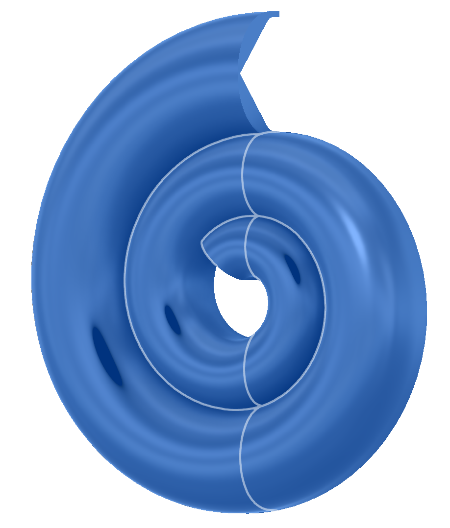
Initial attempts to use an exponential taper for the transmission line meant lofting between 1 surface and another did not come up with equal distances between the sides of the spiral. So work around included making 2 spirals, extruding the shape between them and rounding the edges. This wasn't flexible but did generate the first images and print. Moving to an r squared based spiral allowed for a linear taper between profiles and thus the loft function to work. Figuring that out took many hours as I belligerently wanted an exponential taper. However, by having the width of the inner/terminus smaller in all directions (width and height), than the inlet, a squared relationship can be gained in cross-section area as the line narrows. Looks cool too.
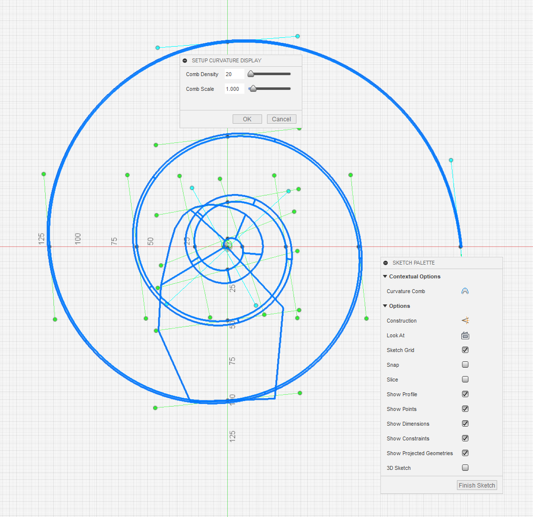
A spiral made of splines has issues at it's ends regarding curvature from Fusion's prospective, for Fusion's own reasons I can't fathom. See below for a curvature analysis of the spline. All's good apart from the centre where it goes wild.
The solution, when wishing to perform a loft from one profile to another is to draw a spline that's longer than needed, then use the create a plane along path tool and not put the planes at the ends - allowing a smooth curve right through the planes of interest.
More faff is caused by Fusion not liking bodies that intersect themselves (which do work sometimes, causing confusion). The solution to that was to use a handy plane (the inlet at the top), to slide the body apart. This is essential as neither simply drawing the objects intersecting themselves or offsetting the outer surface for pleasing overlap were always possible without this.
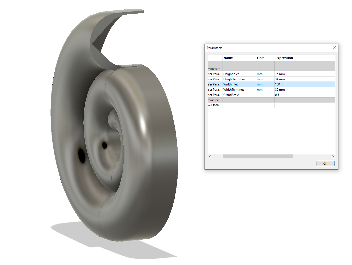
And probably the final part for today is the use of parameters which this project has encouraged. Even though the profile has been split, thickened and scaled, it's still trivial to change the dimensions for a pleasing result - see the difference between the above and below images.
Naturally, I was tempted to call all the dimensions Foo1 to Foo5, but that's because I'm a fool. More sensible names have been chosen, which obviously I'll be glad about if I come back to the project. Width is on the left/right axis. Height for the inlet is up/down, as it is for the terminus when looking it it's profile, even if it is at a bit of an angle now. GrandScale is applied after doing the rest of the drawing to make it small enough to fit onto a printer build platform. From here, I'll juggle the numbers about a bit as the speaker mount is developed.
Here I'll also note the shape of the interior of the profile. It's not rounded, more pent roof. This means no more support. Hurrah!
Randomly - there will be a plinth made to fit with speaker connectors and the crossover within it. A hole shall be drilled in the base and wires poked through for connection. As there will almost certainly be dampening material in it, this may have to be done before assembly.
-
Day 3/Day 4
05/29/2020 at 22:23 • 1 commentThe spare house found over a couple of days have been spent arguing with Fusion360. There has been success. But brain melted, so shall write it up tomorrow.
Also found some old files for a different transmission line design that was never built. Shall roll in some of the ideas.
Knew there would be faff!
-
Day 3
05/28/2020 at 07:08 • 0 commentsFirst half shell printed. Had forgotten how much fun removing support materials is. Redesign coming this weekend.
-
Day 2
05/27/2020 at 16:54 • 0 commentsBusy printing.
The centre line of the transmission line is about 0.8 m long. If undamped, this would have a 1/4 wave resonance at 106 Hz, this is quite a bit lower than the 175 Hz resonance of the driver in free air. However, the plan is to heavily dampen it to avoid issue with resonances. There may be a small amount of reinforcement around 106 ish Hz which would be helpful too. The little driver should see a perfectly absorbent transmission-line and give a clean and clear response with a pleasant and gradual bass roll off.
Going for too long a line was purposful, deeper clean bass, even if attenuated is quite nice. A roll off at the resonance would be perhaps a bit too high. Considering that they will generally be playing music from a PC that's running Equaliser APO, with a profile tailored to flatten their response and extend the bass a bit, longer seemed better than shorter. Also it looks cool.
-
Day 1
05/27/2020 at 16:38 • 0 commentsHave considered lots of iterations of transmission line speaker designs over the years. Several attempts, including an unwieldy but excellent sounding 12" guitar driver experiment have been fun to tinker with. But it's lock-down, I've been bored for weeks and have been hoarding audio gear for ++aeons.
So, using the excuse of learning a bit more about CAD, generating some 3D printable snail shaped transmission-line speakers is the present attempt to avoid cabin fever.
The ingredients are:
- Lots of coffee
- A pair of KEF Uni-Q satellite speakers (from a set of 5 almost identical units)
- Fusion 360
- A 3D printer
- Time
Thus far, the progress has been to understand roughly what the drivers are and faff about with Fusion 360 to generate the enclosures.
The drivers are - KEF 8900-6090+Q. Which Room EQ Wizard usefully showed to have a 175 Hz resonance. They do have a built in crossover, which can be modded to open up the bass a bit (short out the input capacitor). As there's no plan of putting much power through them, this should be OK, and a transmission line should limit cone excursion a bit around resonance too.
The snail shell was assisted greatly with the Equation Driven Curve app. It's great, even if the coordinates flip about a bit. It took ages to finally generate the shape. Essentially involved offsetting a line 0.1 mm from an exponential spiral, then extruding the shape and rounding the edges with a variable radius fillet. Then using the shell command to open it up and extruding through the bass to make half of a snail shell. All joined together by offsetting the outside surface to thicken it and get rid of the gap. Keeping it small enough to fit on a printer platform while allowing a large enough opening to later design and attach the speaker was time consuming. The results are the first renders in the project's pictures.
Speakers that look like snails
Transmission line speakers - attempting form and function.
 Lightning Phil

