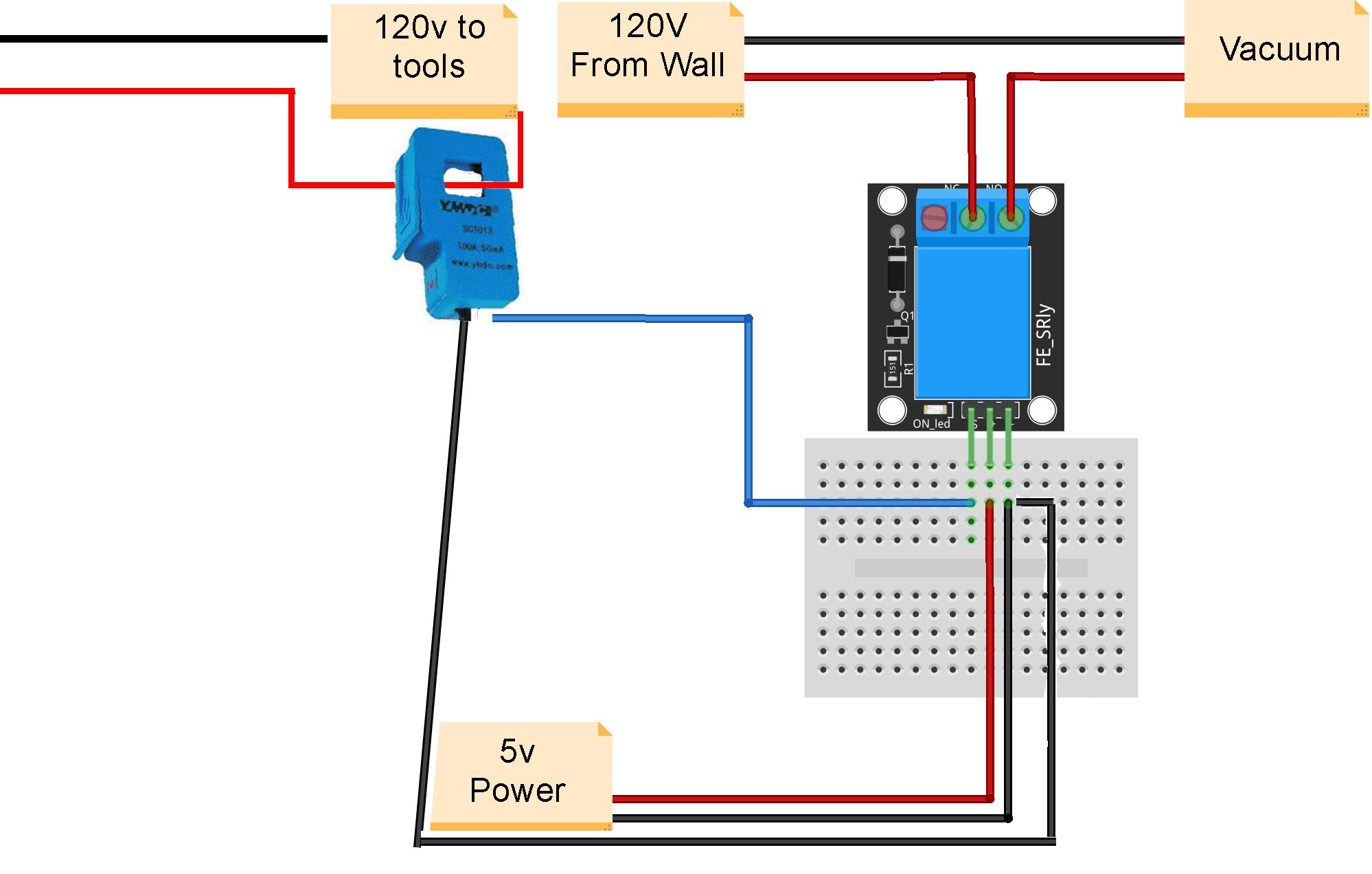
Here is a diagram of the first version of my switch. I used a simple arduino relay module as the relay. This worked in testing but once I tried with with my vacuum it failed. I didn't take into account how much amperage the vacuum would draw at startup and the relay was only rated for 10a. I also used a 5v power supply to power the relay as that is what it required. I later found that by coiling wire through my current sensor https://amzn.to/36LRGw1 I could create enough voltage to trigger the relay without the outside 5v power supply. This simplified things a bit as I wouldn't need to provide another outlet for steal power from some other device.
In version 2 I replaced the relay with at larger version that is rated for 40 amps. https://amzn.to/36ycZ3W. This eliminated the bottleneck and allowed the vacuum to start. The problem now is that when the relay triggers it was not providing a full 120v to the vacuum. The other previous relay was not picky when it came to AC or DC as long as the signal was at least 5v. But the new relay would only properly work using a DC signal. At first I thought I would be forced to use an outside power supply after all but then I decided to build a simple rectifier to convert my 7v AC to DC.
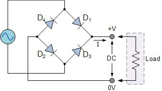
 So here's a diagram of what I needed. It's a pretty simple circuit and all you need are 4 diodes and a capacitor to smooth out the voltage. Since I didn't have any diodes around and currently everything is taking much longer to ship I decided to use LEDs due to having alot of them laying around. Since an LED is a light emitting diode I thought it was a good solution and has the added benefit of lighting up when current is applied. So I reduced the number of coils on the current sensor to lower the incoming voltage from it and used the new rectifier to make my DC signal and it works perfectly.
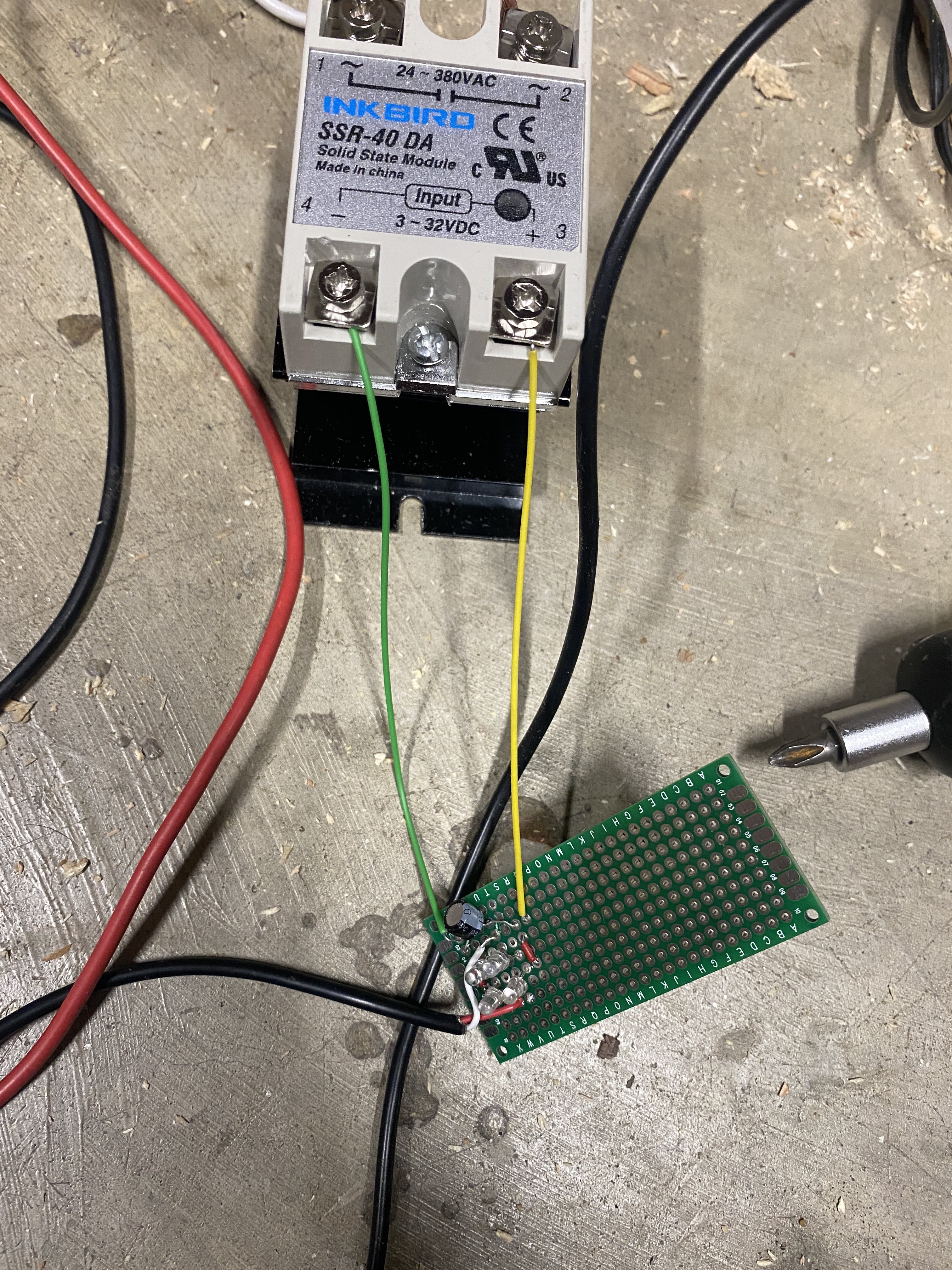
Heres a photo of the first test version. I'm going to try to reduce the size of everything to make it easier to package for the final build.
If anyone has any questions or comments I'm glad to hear them. While this probably isn't useful to many people I think it could be helpful to someone so I wanted to document what I've done.
Here's a video of everything in action.
https://cdn.hackaday.io/files/1719887358334592/joined_video_d53110c447954b3e8f3c3baaa821a053.MP4
 Will Stone


I’m a woodworker who wouldn’t know a rectifier from a rectal thermometer. But man this looks very awesome and will be interested in what the final version is and would like to try this.