-
1Collect the Essentials
![]()
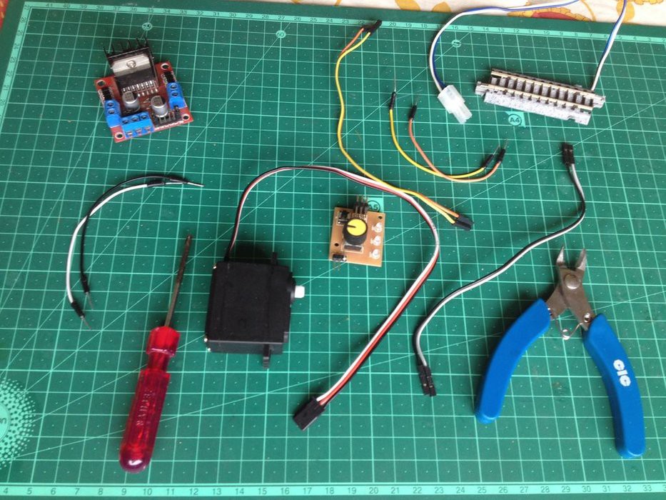
So here is what you will need:
- A standard servo motor(Plastic gear one is recommended since the mechanics of the servo motor will be unused.)
- A screwdriver
- A diagonal cutter
- Some M-M jumper wires
- A power feeder track(Use a suitable gauge of track that you have, I use N-gauge tracks)
- Some F-F jumper wires
-
2Take Apart the Servo Motor
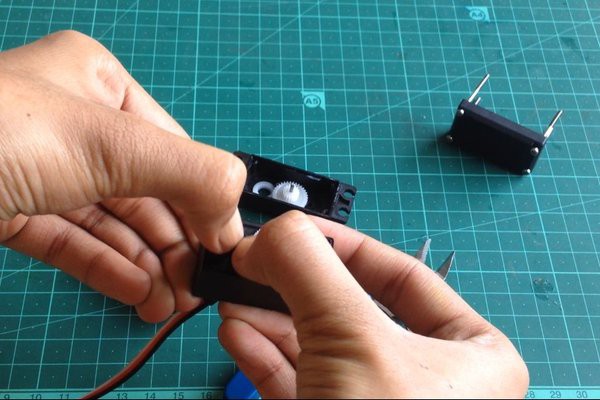
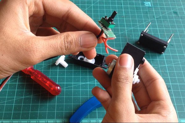
Unscrew the bottom cover of the servo motor to reveal the driver board inside.
-
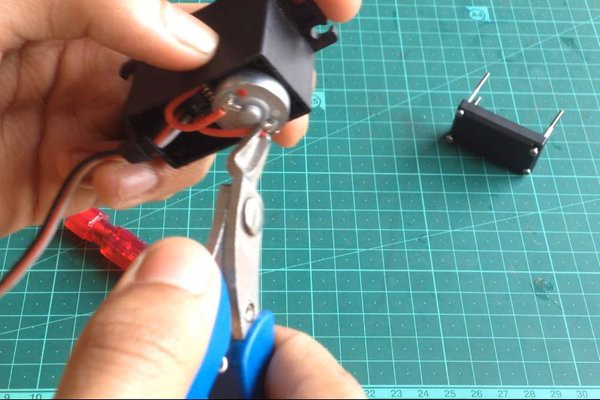
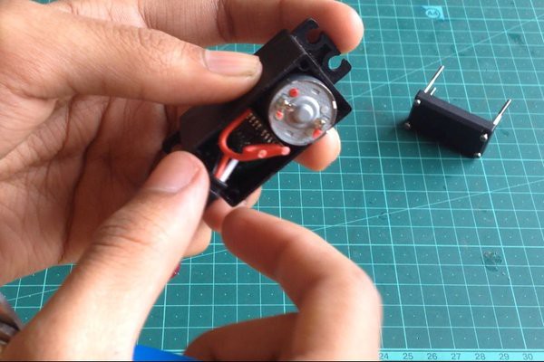
3Disconnect the Motor Wires
![]()
![]()
-
4Take Out the Servo Driver
![]()
![]()
Remove the top gear housing and the output gear to expose the potentiometer. Push it down to free it from the servo motor's body and take the driver board out along with the potentiometer.
-
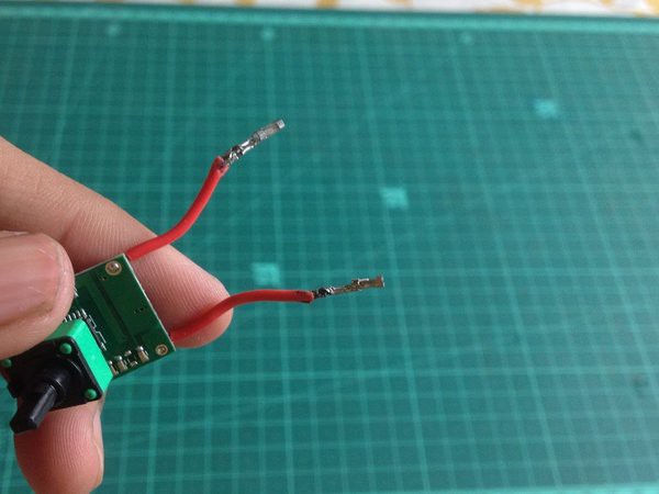
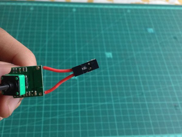
5Add Female Connectors to the Output Wires of the Driver Board
![]()
![]()
Doing so will make it easier to connect the servo driver's output to the L298N motor driver's input pins.
-
6Connect Jumper Cables to the L298N Motor Driver
![]()
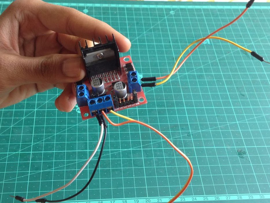
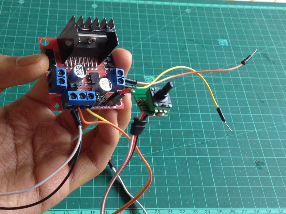
Take a pair of jumper cables with female connectors on one side and bare wires on the other and connect the bare wires to the 5 volts and GND of the motor driver board. Using a pair of male to male jumper cables, connect the 12-volt input of the motor driver board(also marked as VIN or VMOT) and the GND to be later connected to a 12-volt power supply. Then, take another pair of male to male jumper wires and connect to any of the two motor outputs.
-
7Connect the Servo Driver Board
![]()
Connect the output wires of the servo drive to the input pins of the motor driver corresponding to the motor output the power feeder track will be connected to. For example, if the outputs 3 and 4 are being used(see image), connect the servo driver's output to the input pins marked 3 and 4.
-
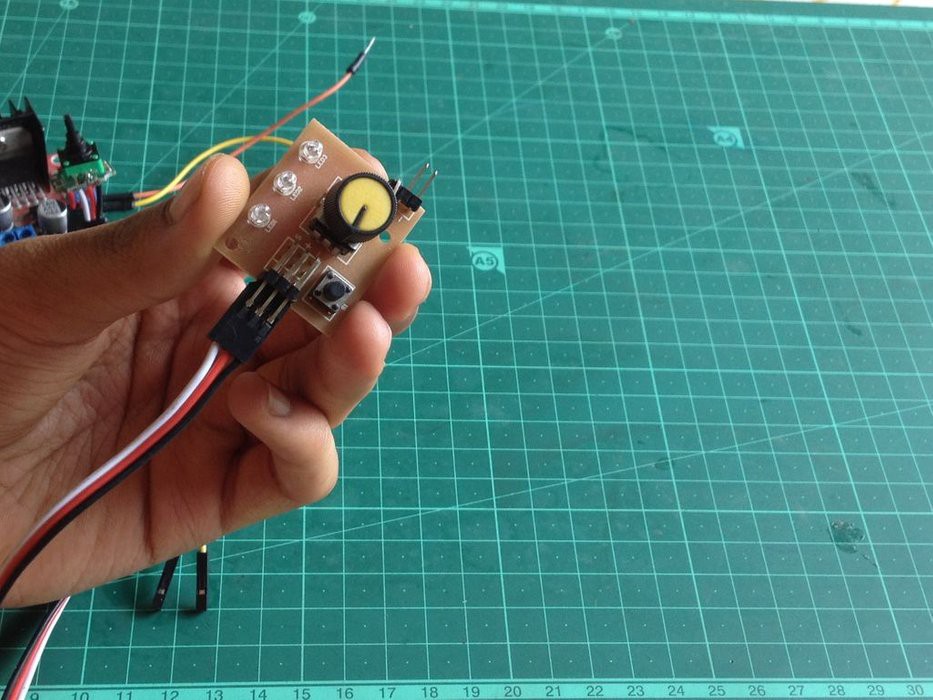
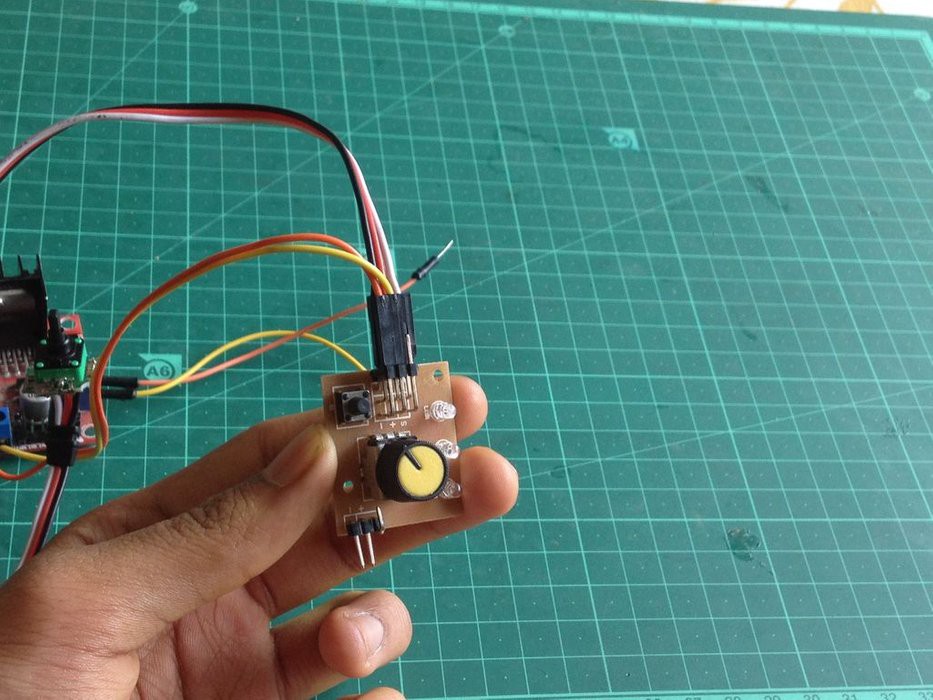
8Connect the Servo Tester to the Servo Driver Board
![]()
-
9Connect the Servo Driver's Power Input to the 5 Volt Output of the Motor Driver
![]()
-
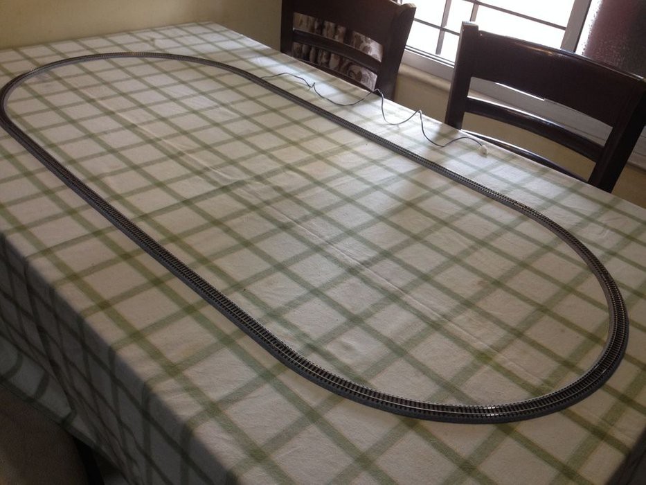
10Make the Test Layout
![]()
The test layout is just a loop of track made using N-gauge Kato Unitrack.
HACKED! Servo Motor As Model Train Driver!
Make your own low-budget train controller by hacking a servo motor.
 KushagraK7
Discussions
Become a Hackaday.io Member
Create an account to leave a comment. Already have an account? Log In.