 KushagraK7
-
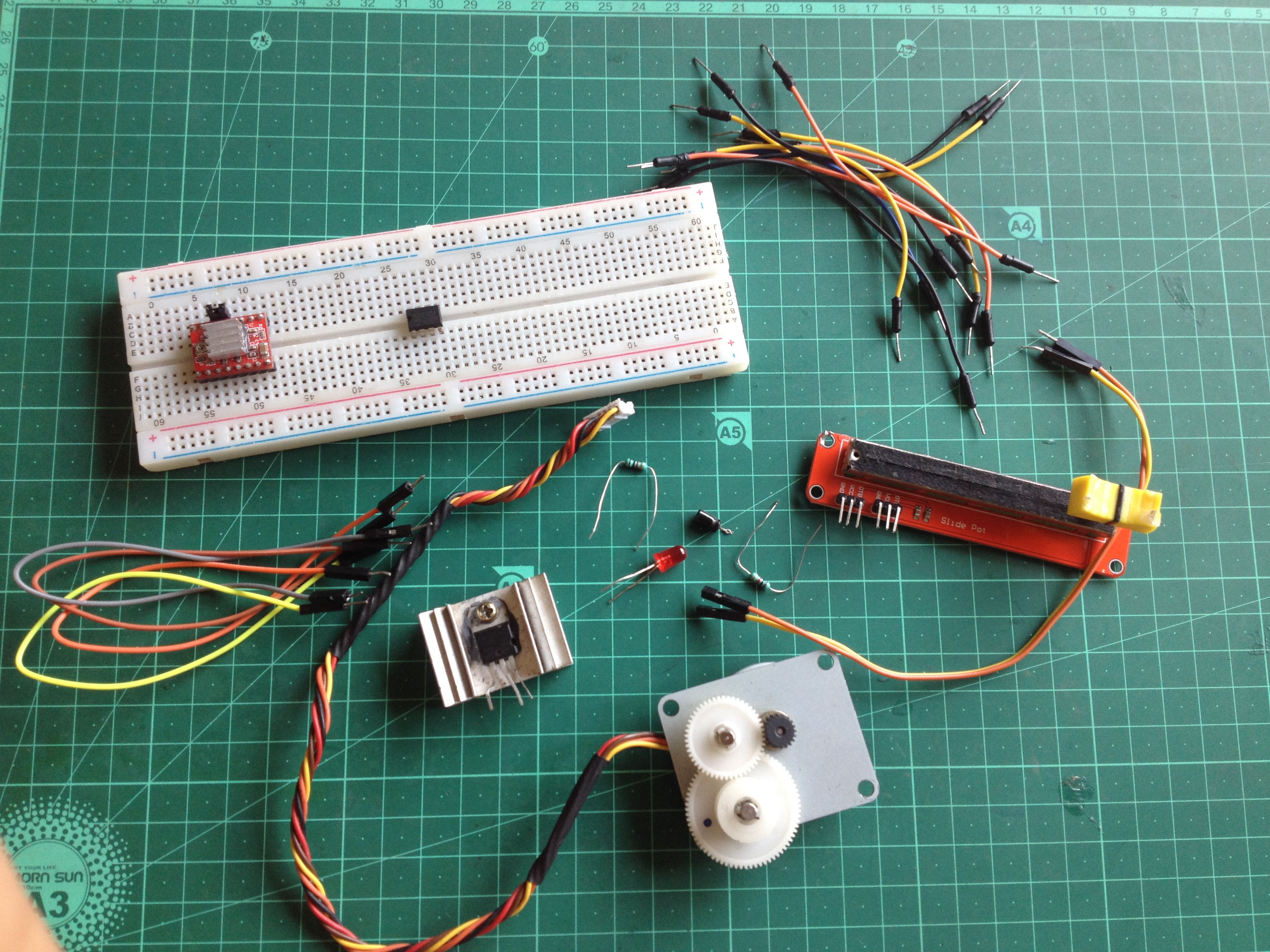
1Get All the Parts and Componenets
![]()
Here is what all you will need:
- An NE555 timer IC
- A stepper motor
- An A4988 stepper motor driver
- A breadboard
- Some jumper wires
- Any capacitor between 1 and 47 uF
- A 10k Ohm potentiometer(Also, try using a 100k one)
- A 9-12 volt DC power source
- A 1k Ohm resistor
- An LED(Optional)
- A 1k Ohm resistor(For the LED)
- A voltage regulator with a 5-volt output(L7805CV, use a regulator if you don't have a separate 5 volts power supply)
-
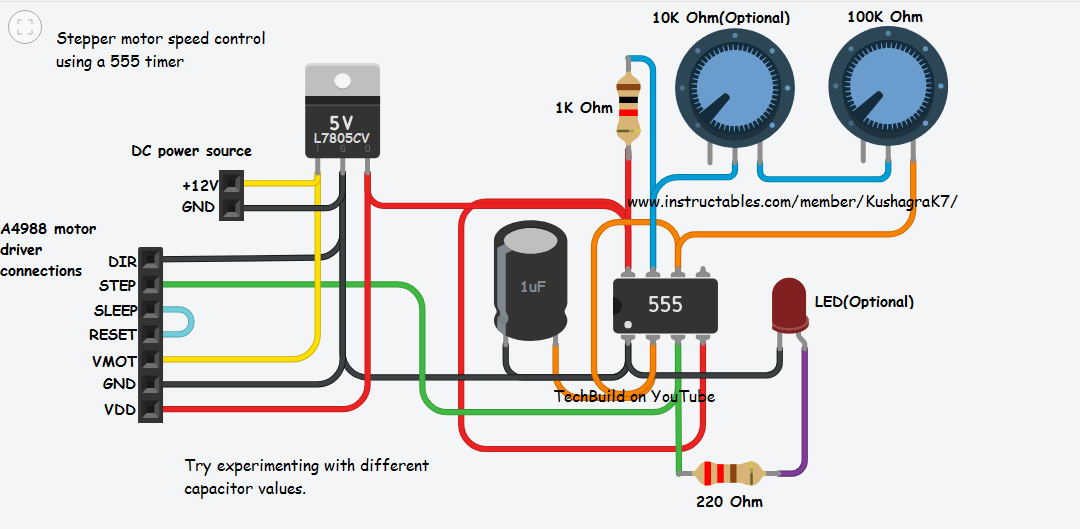
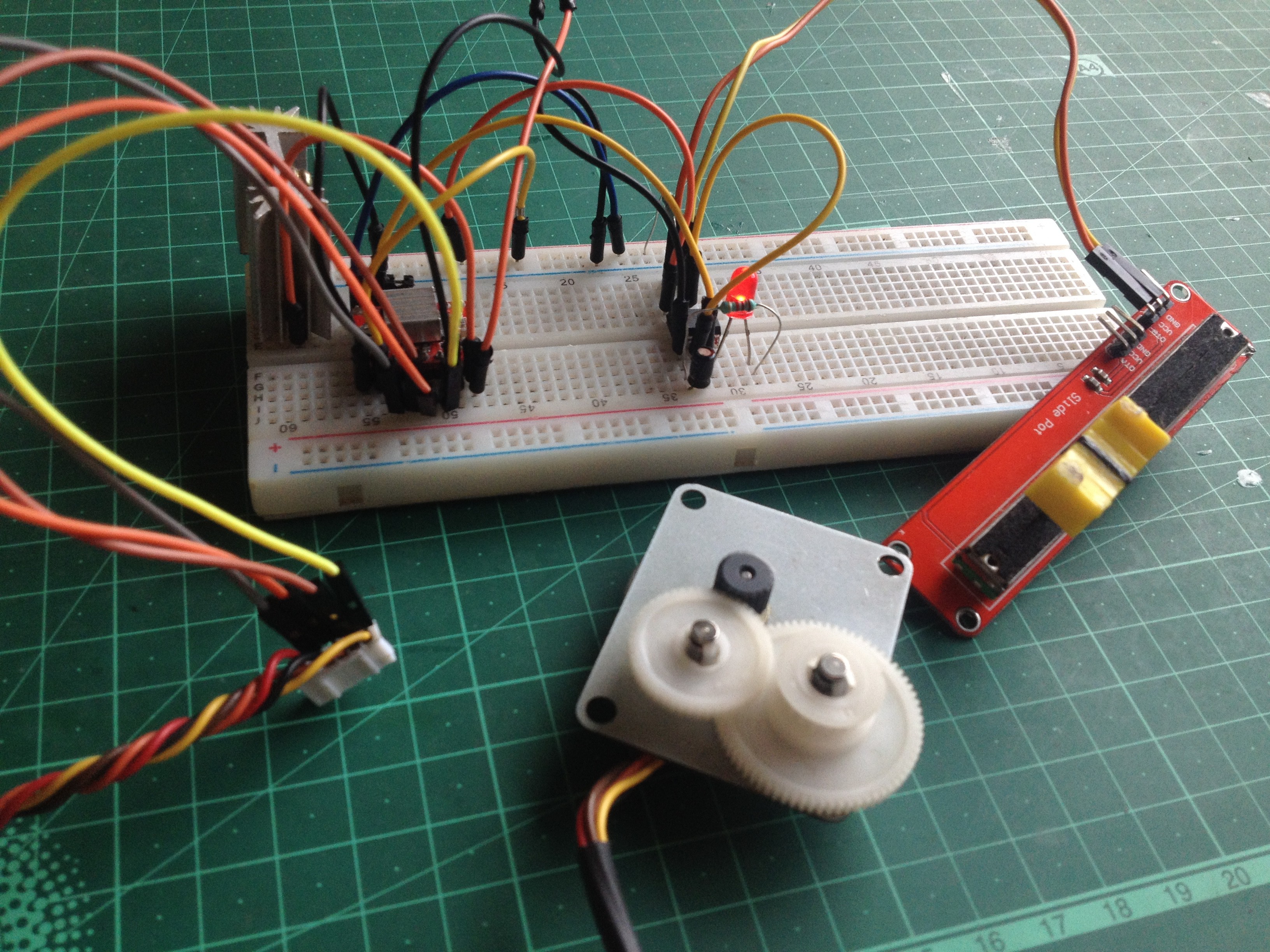
2Follow the Circuit Diagram and Set Up Everything
![]()
Follow the circuit diagram(click on it to get full view) and start by plugging on the 555 timer IC and the motor driver on the breadboard.
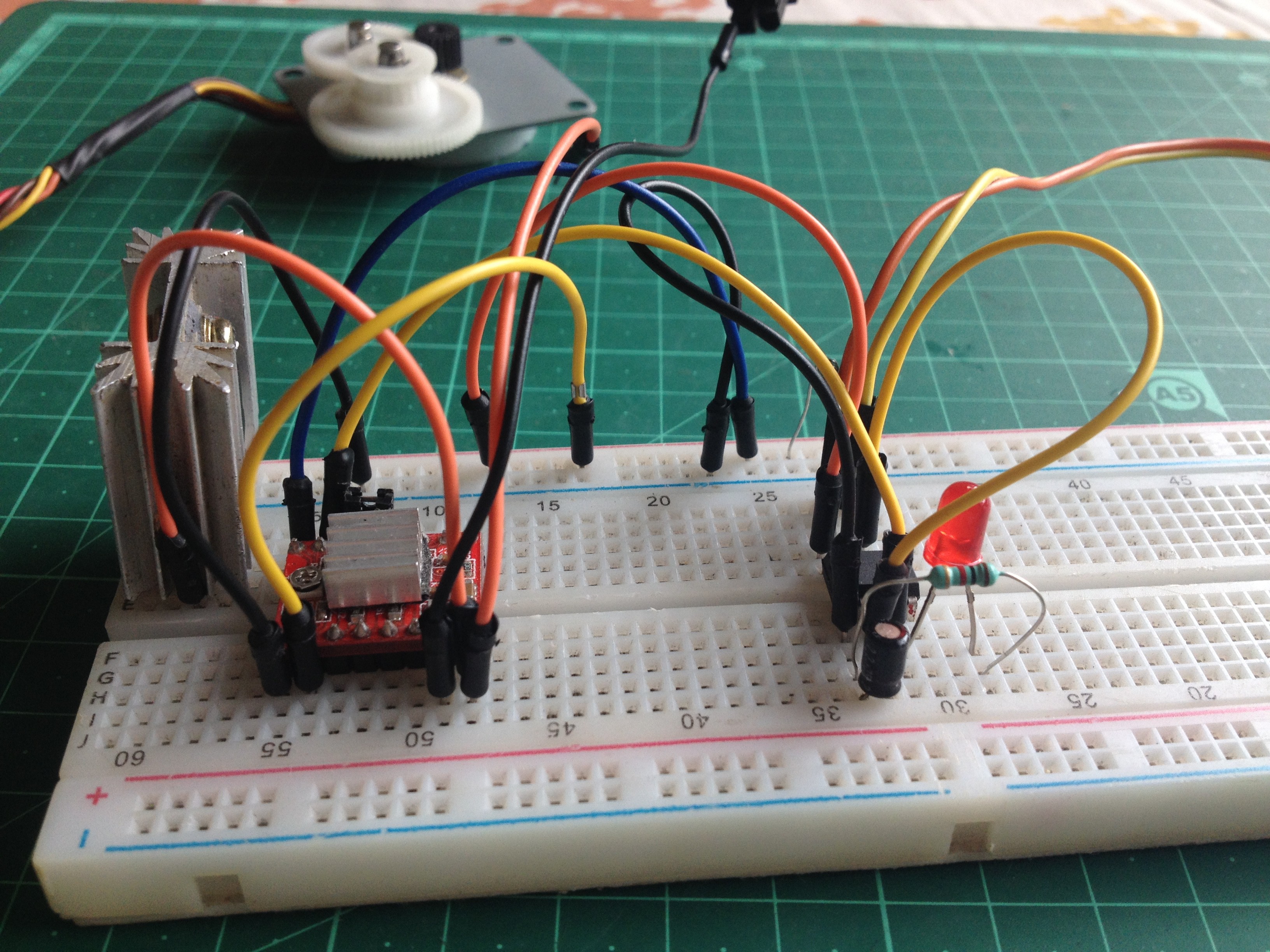
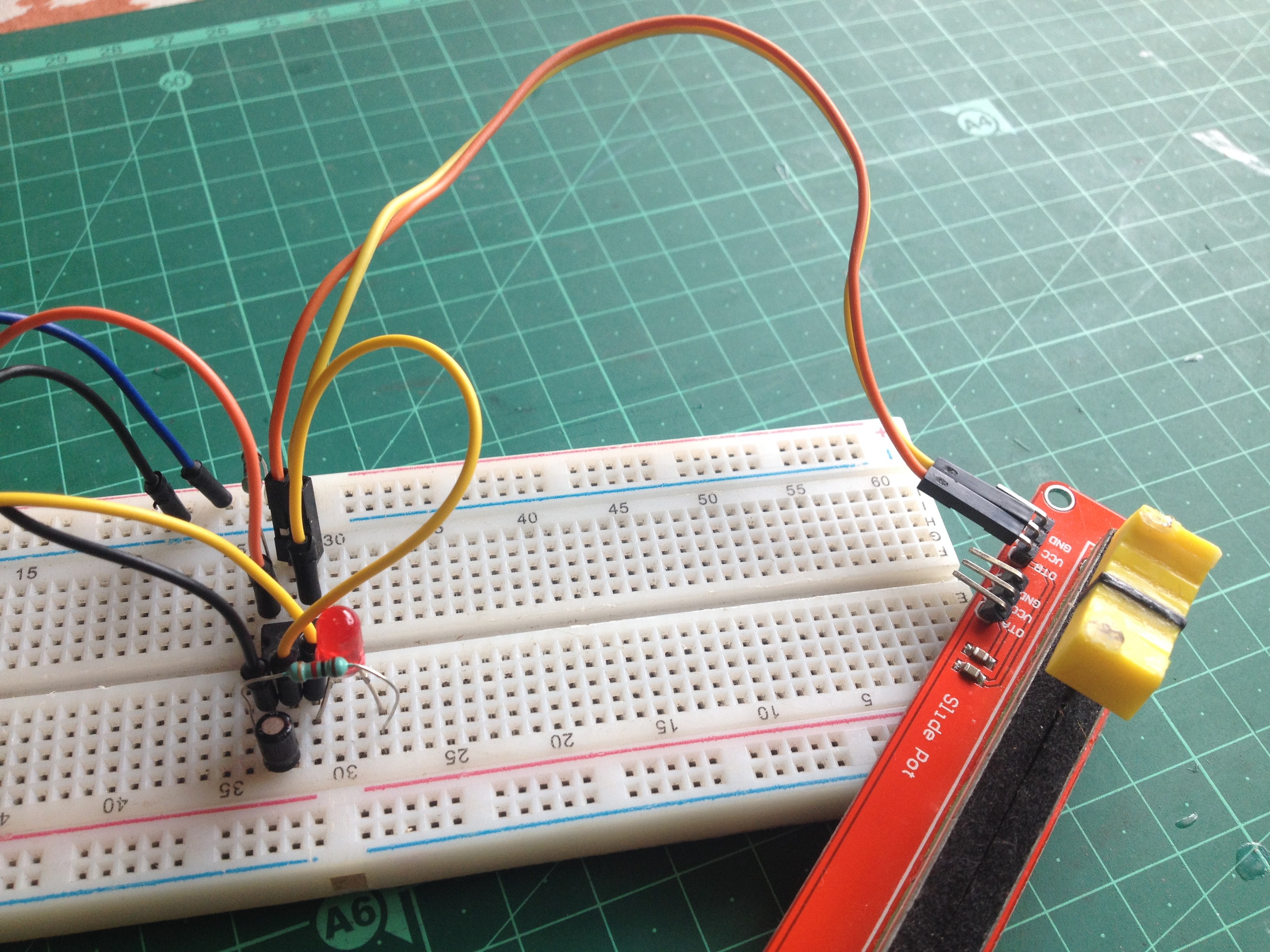
![]()
![]()
Then, continue by connecting the capacitor and resistors to the 555 timer IC. Check the images above for reference.
-
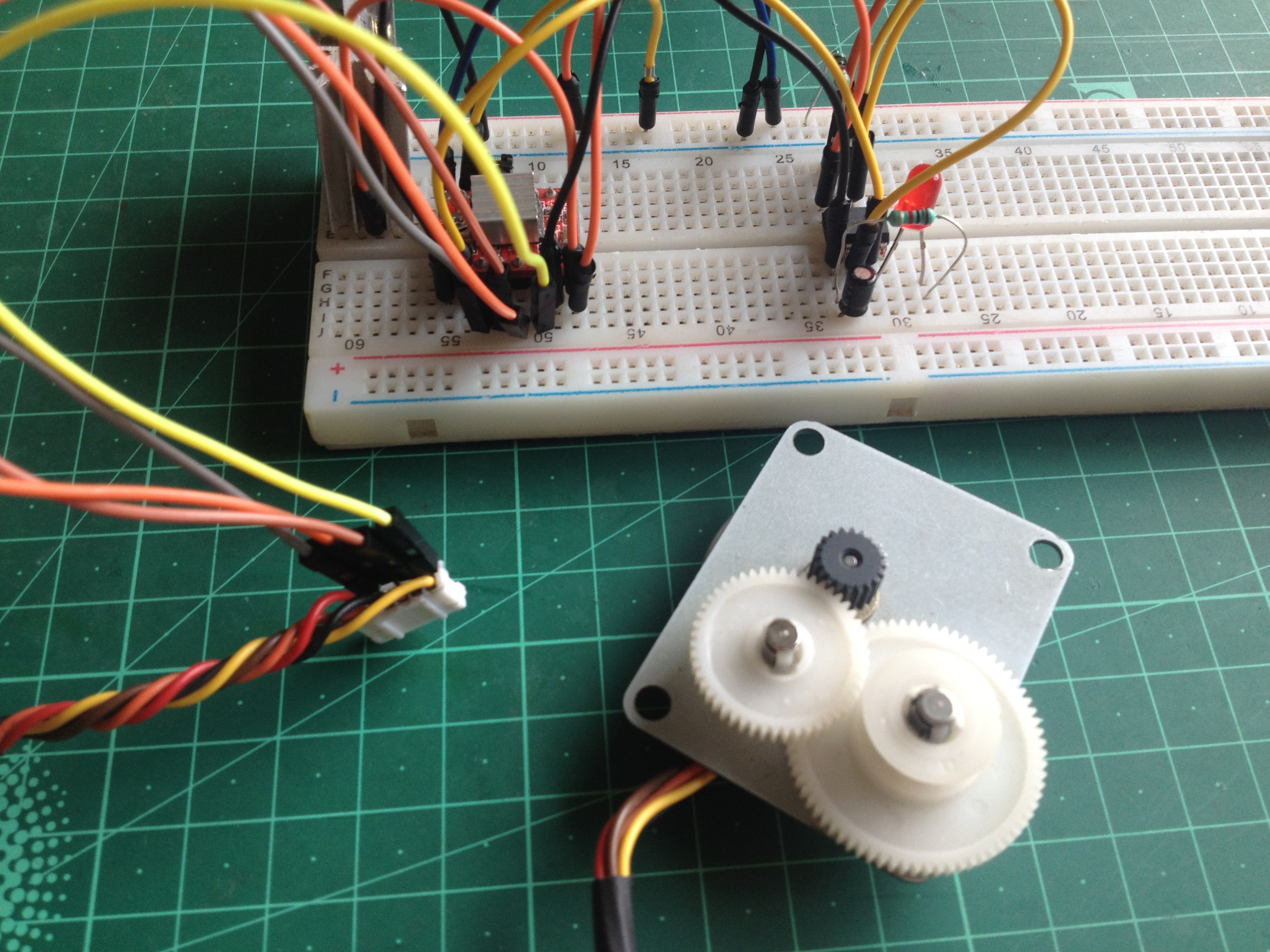
3Connect the Stepper Motor to the Motor Driver
![]()
Connect the two pairs of the stepper motor's wires to the outputs of the A4988 driver board. Connect 1A and 1B to the first pair and 2A and 2B to the second one.
-
4Connect to Power and Turn It On
Double check all the wiring connections. The 555 timer IC and the A4988 motor driver's logic circuitry will require 5 volts. Since the 555 timer generates the output pulses with peak voltages equal to the supply voltage, you will not want any higher voltage signal to go in the motor driver's input. Use a voltage regulator if you have a single power input(12-volt) to get 5-volt output for the logic and control circuitry.
![]()
-
5Is It DONE?!
Don't stop here! Try experimenting with different values of resistors and capacitors. Also, this project can prove to be useful for stepper motor harvesters who take apart printers and similar stuff to get stepper motors and test them for performance.
Stepper Motor Speed Control With a 555 Timer
Use a 555 timer and a Step/Dir stepper motor driver to run a stepper motor without a microcontroller.
Discussions
Become a Hackaday.io Member
Create an account to leave a comment. Already have an account? Log In.