-
Oath 2.0 example I found
06/15/2020 at 04:37 • 0 commentsIm waiting on my parts which should arrive this week. In the meantime I found this additional example which might work if We want to make the alarm Status secure: https://github.com/8bitkick/ArduinoGoogleAPI/blob/master/GoogleAPI.ino
-
Found some example wifi shield code
06/09/2020 at 03:13 • 0 commentsI'm not sure if I mentioned the wifi shield will be needed. I found some great examples of using the wifi shield to communicate with the internet. Here is a page which talks about setting up the wifi code: https://www.arduino.cc/en/Tutorial/WiFiWebClient
/*
  Web client

 This sketch connects to a website (http://www.google.com)
 using a WiFi shield.

 This example is written for a network using WPA encryption. For
 WEP or WPA, change the Wifi.begin() call accordingly.

 This example is written for a network using WPA encryption. For
 WEP or WPA, change the Wifi.begin() call accordingly.

 Circuit:
 * WiFi shield attached

 created 13 July 2010
 by dlf (Metodo2 srl)
 modified 31 May 2012
 by Tom Igoe
 */


#include <SPI.h>
#include <WiFi.h>

char ssid[] = "yourNetwork"; //  your network SSID (name)
char pass[] = "secretPassword";    // your network password (use for WPA, or use as key for WEP)
int keyIndex = 0;            // your network key Index number (needed only for WEP)

int status = WL_IDLE_STATUS;
// if you don't want to use DNS (and reduce your sketch size)
// use the numeric IP instead of the name for the server:
//IPAddress server(74,125,232,128);  // numeric IP for Google (no DNS)
char server[] = "www.google.com";    // name address for Google (using DNS)

// Initialize the Ethernet client library
// with the IP address and port of the server
// that you want to connect to (port 80 is default for HTTP):
WiFiClient client;

void setup() {
  //Initialize serial and wait for port to open:
  Serial.begin(9600);
  while (!Serial) {
    ; // wait for serial port to connect. Needed for native USB port only
  }

  // check for the presence of the shield:
  if (WiFi.status() == WL_NO_SHIELD) {
    Serial.println("WiFi shield not present");
    // don't continue:
    while (true);
  }

  String fv = WiFi.firmwareVersion();
  if (fv != "1.1.0") {
    Serial.println("Please upgrade the firmware");
  }

  // attempt to connect to Wifi network:
  while (status != WL_CONNECTED) {
    Serial.print("Attempting to connect to SSID: ");
    Serial.println(ssid);
    // Connect to WPA/WPA2 network. Change this line if using open or WEP network:
    status = WiFi.begin(ssid, pass);

    // wait 10 seconds for connection:
    >span class="br0">(10000);
  }
  Serial.println("Connected to wifi");
  printWifiStatus();

  Serial.println("\nStarting connection to server...");
  // if you get a connection, report back via serial:
  if (client.connect(server, 80)) {
    Serial.println("connected to server");
    // Make a HTTP request:
    client.println("GET /search?q=arduino HTTP/1.1");
    client.println("Host: www.google.com");
    client.println("Connection: close");
    client.println();
  }
}

void loop() {
  // if there are incoming bytes available
  // from the server, read them and print them:
  while (client.available()) {
    char c = client.read();
    Serial.write(c);
  }

  // if the server's disconnected, stop the client:
  if (!client.connected()) {
    Serial.println();
    Serial.println("disconnecting from server.");
    client.stop();

    // do nothing forevermore:
    while (true);
  }
}


void printWifiStatus() {
  // print the SSID of the network you're attached to:
  Serial.print("SSID: ");
  Serial.println(WiFi.SSID());

  // print your WiFi shield's IP address:
  IPAddress ip = WiFi.localIP();
  Serial.print("IP Address: ");
  Serial.println(ip);

  // print the received signal strength:
  long rssi = WiFi.RSSI();
  Serial.print("signal strength (RSSI):");
  Serial.print(rssi);
  Serial.println(" dBm");
}
The next step will be to connect to the google sheet. I plan on using an HTTP Post to post to the Google sheet. Here is some example code for that: (from here: https://www.arduino.cc/en/Tutorial/WiFiWebClientRepeating) - I'm modifying it some as I go on this example:
// this method makes a HTTP connection to the server:
void httpRequest() {
  // close any connection before send a new request.
  // This will free the socket on the WiFi shield
  client.stop();
// I want to update this to goto a Google Sheet for example like this: https://docs.google.com/spreadsheets/d/{{spreadsheetId}}/edit#gid=0

  // if there's a successful connection:
  if (client.connect(server, 80)) {
    Serial.println("connecting...");
    // send the HTTP PUT request:
    client.println("POST /spreadsheets/d/{{spreadsheetId}}/edit#gid=0 HTTPS/1.1");
    client.println("Host: docs.google.com");
    client.println("User-Agent: ArduinoWiFi/1.1");
    client.println("Connection: close");
    client.println();

    // note the time that the connection was made:
    lastConnectionTime = millis();
  } else {
    // if you couldn't make a connection:
    Serial.println("connection failed");
  }
}
This is all pseudo code and untried. I need to order my Wifi Shield..
-
Excited to have another person helping!
06/09/2020 at 02:45 • 0 commentsI am excited that another person is contributing. Pretty cool! Thanks for the help! So I just added a quick high level diagram of the end goal of the project. I will also try to get some code completed (or pseudo code at least) for the Arduino -> Google Sheets part of this. With Entunassa helping with the circuit, I thought I could make some progress on the internet connectivity side of things. I have to order some more parts so while I am waiting on those I will be working mockups/ pseudo code for some of the smart components.
![]()
The idea is that once the LED circuit is setup and calibrated, the Arduino will sense the status of the LEDs and send that info to a Google Sheet. Why a Google sheet? Its free, and it is on the public internet. This is a way to see the status of the alarm when you are not at home because it is on the public internet. But the Google sheet is just a place to capture the info. To display the status, there are multiple options. You can use a google site (also free) which has some javascript to look at the Google sheet entries and displays the last status at all times on the web site. Or option 2, you can create a Smart App to show the status. I want to try both option 1 and option 2. I have a Samsung SmartThings Hub and i want to create a SmartApp and SmartDevice registered that will show the status of the alarm. Also, I have Alexa so i hope to make an Alexa skill to tell me and show me the status via the Alexa app and Alexa devices (like the Echo, etc.)
-
Testing the sensor circuit
06/05/2020 at 18:05 • 2 commentsEntunassas Contribution 1 (02 Jun 2020):
Hey Eric, thanks for team working here. ☺ Hi, I´ve tested the following:
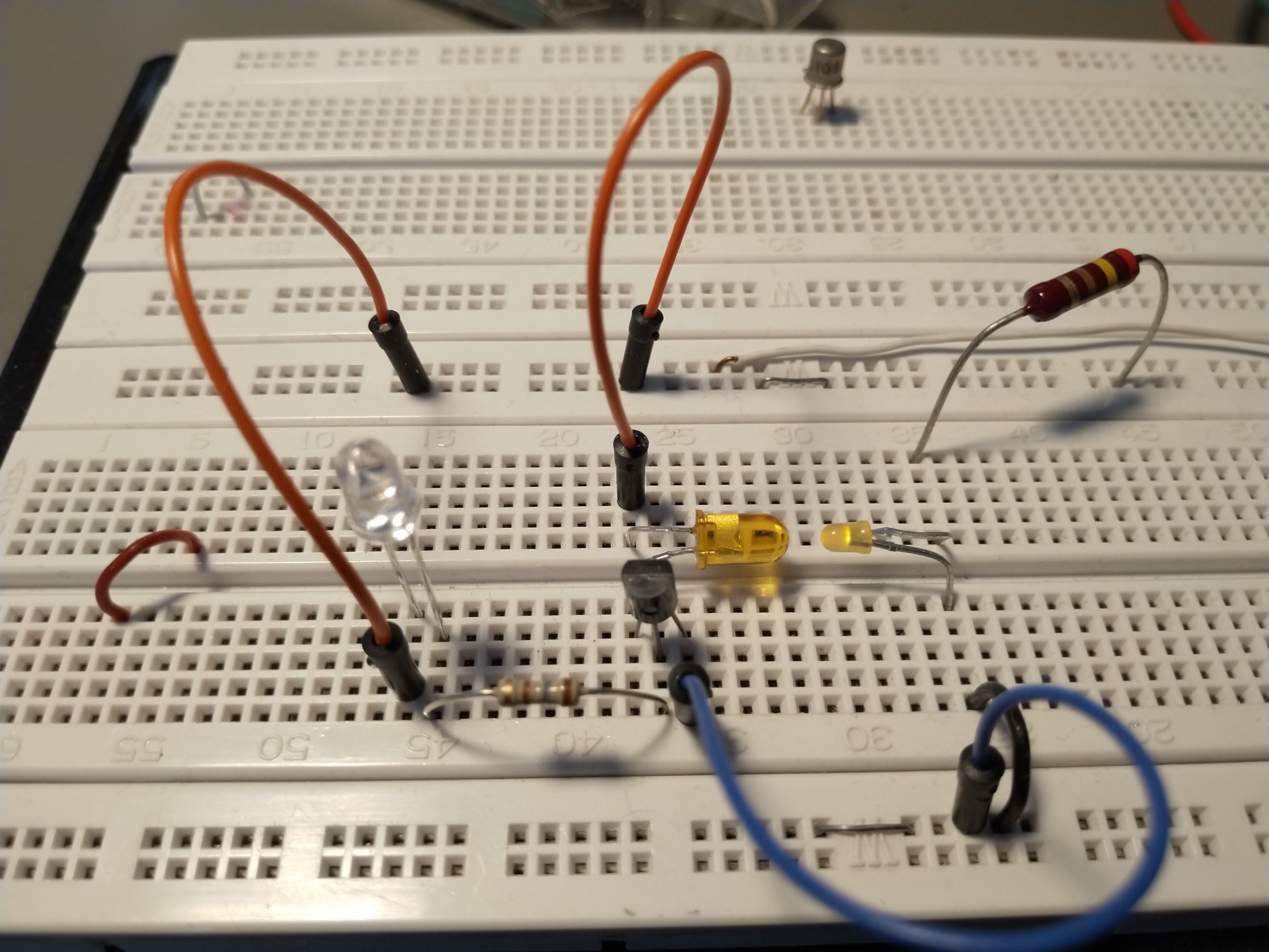
![]()
Yellow LED at the right may represent the STATUS LED (3mm yellow, matte). In their opposite a yellow LED as a sensor, followed of a small amp. circuit. STATUS LED is driven by 5V over 120R (15...20mA).
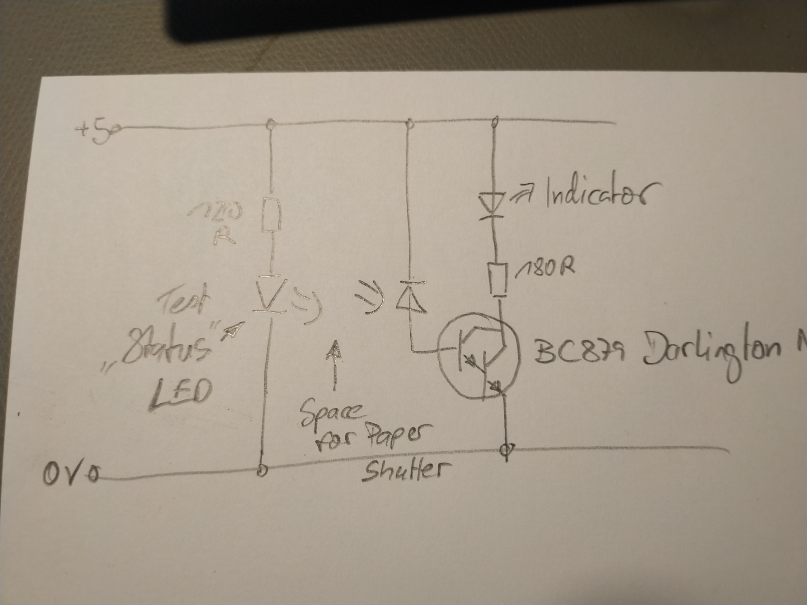
![]()
The circuit. I choosed a darlington NPN for amplifying the microamperes from the sensor. First Result: Didn´t work, indicator LED is glowing really poor (it´s current is *way* lower than expected: << 0,1mA), even if i reduce the gap between the LEDs to zero. -/-
Entunassas Contribution 2 (04 Jun 2020):
I total the circuit works: If I let glare a bicycle headlight onto the sensor LED, the indicator shows a full light ( = ON). Unfortunately, we have a poor light source to detect. I´ve tried to improve the circuit:
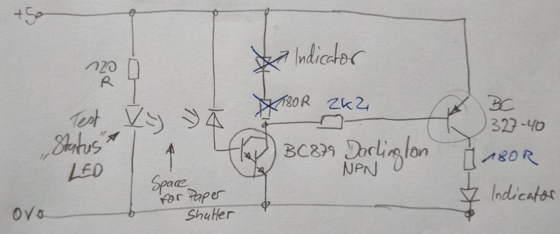
![]()
I have added a second transistor; this assembly acts as a triple-Darlington circuit.
The current senitivity of it is extremely high, in fact, but the indicator LED even shows a tenuous glow. I predict we´ll run into a problem when using a LED as a sensor. We need more amplifying then a single transistor (and also two in a row) can offer.
Entunassas Contribution 3 (05 Jun 2020):
Hmm, neither the DARLINGTON, nor the SZIKLAY circuit will match our needs. You wrote in the discussion: " [...] another transistor in a traditional way (after the amplification) to 'enable' a transistor which would then let the status indicator led light up." This was my idea with the above shown circuitry: Getting the highest possible current amplification from two transistors, which should be >1000 from the left one, multiplied with around 400 from the right one. I can´t believe that there is something wrong - if I touch the Sensor-LEDs legs gently with my finger, that minimal current lasts to light the indicator very well. Maybe the LEDs are scrap. I´ll check other combinations.
You have mentioned the Texas Instruments "Boomer" LM4675. Its purpose is to drive an 8 Ohms speaker pair. The chip has no extensive current gain but a power stage. I would say it is not suitable for what we want to do.
I had googeled around and found a circuit using a simple CMOS stage (CD40106 Schmitt Trigger), but I can´t retrieve that page 'cause I forgot to save the link (how silly).
I have payed attention, however and hope to bring up a test result in my next contribution ☺.Entunassas Contribution 4 (07 Jun 2020):
I´ve tested the circuit from C. 2 with another SENSOR LED. It is working after a fashion, it is neither full ON nor completely OFF. See video footage VID_C4 under "files". Not suitable for you! I would discard that path.
As mentioned in C. 3, there is a further idea, stolen from another website (:laugh:) ...Entunassas Contribution 5 (07 Jun 2020):
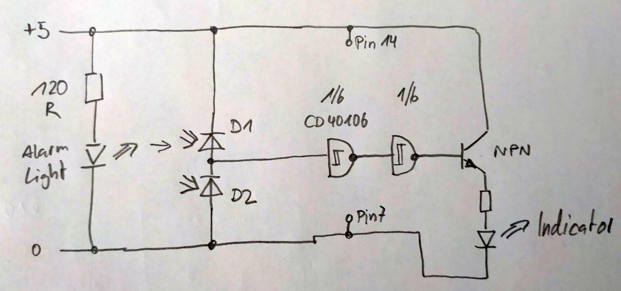
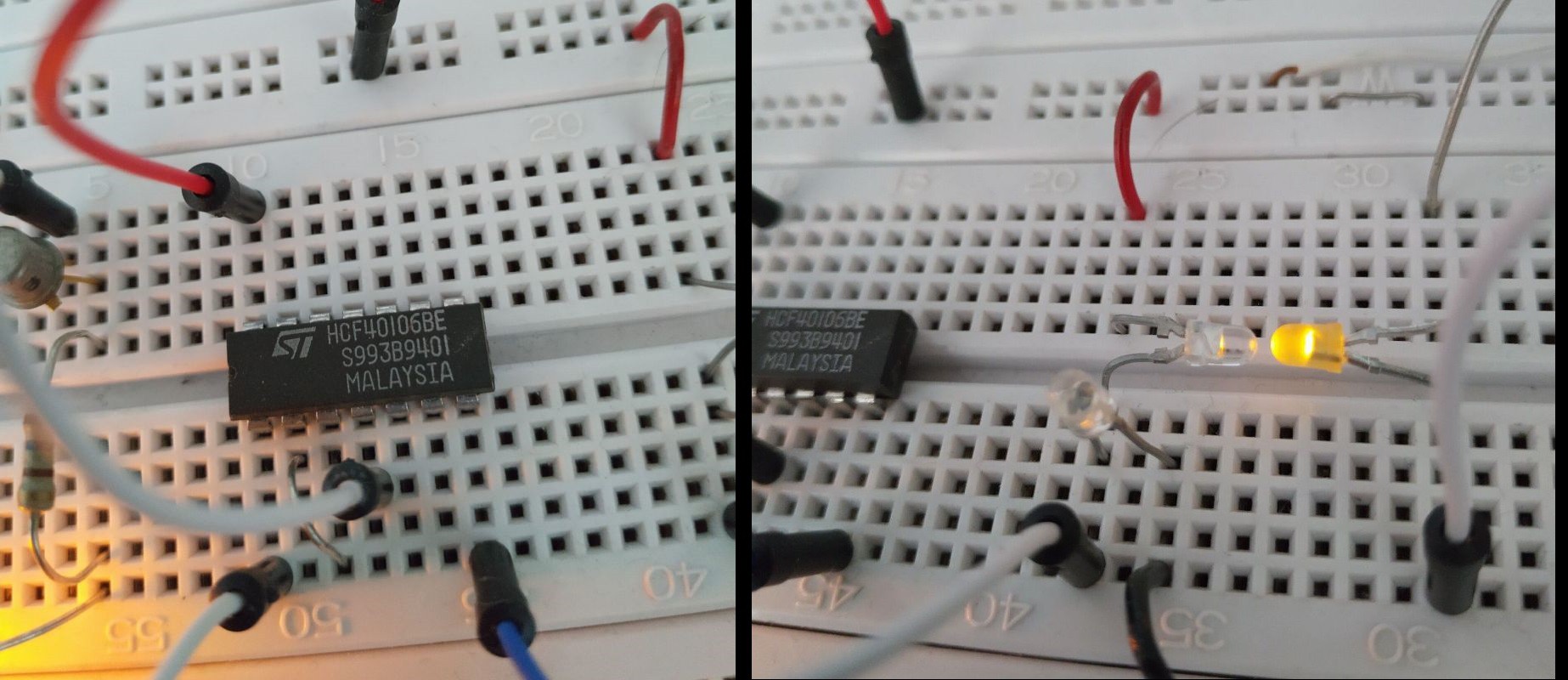
![]()
I patched that on my bread board.
![]()
(Readers may ask themselves: Why has Entunassa all these parts at home? Answer: Simply collected from projects over decades).
OK, does it work? See VID_C5 under "files".
How does it work? Referring to the IC 40106 datasheet (PDF) we are told it has a FET input, which draws no current from the connected circuit.We start wit the SENSOR diode. Power Supply is 5V. There are two identical LEDs in a row, both are drawing a tiny current. The resulting circuit could be depicted by two super-high-ohm resistors in series. This point between D1 and D2 (called INPUT) shows 1/2 of the 5V (regarding Ohm's Law), assumed both LEDs (D1, D2) are illuminated in the same brightness.
If the SENSOR LED (D1) receives more light, eg. from the DAP (dumb alarm panel), its internal current rises (its imaginary 'resistor' goes down) and the resulting voltage on INPUT rises.
If ambient light changes, it has alsmost no effect, because both LEDs are affected (no ratio change of their internal 'resistors'). Nevertheless a sharp tuning will be necessary to find the suitable balance to detect the DAP light.
You can use D1 or D2 as SENSOR LED. The INVERTER gate output is low-active when D1 detects light, or just high active when D2 detects light.
The very best fact is: For full interfacing to ARDUINO is no aditional part necessary.
This circuit has many advantages:
- only a few small and cheap parts;
- backlight suppression included (in a moderate range);
- six interfaces in one IC;
- 5V can be taken from ARDUINO;
- Output of 40106 can be connected directly to ARDUINO inputs
Eric, now it´s your turn :thumbs up:
Entunassas Contribution 6 (09 Jun 2020):
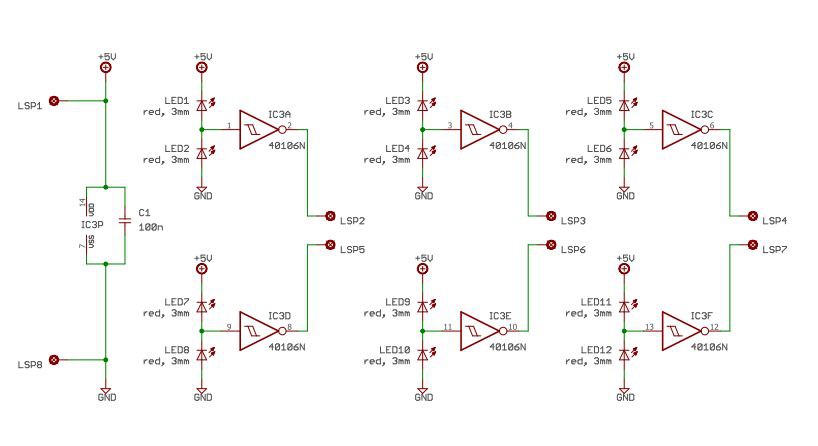
Find the final schematic V1 in section "Files" (PDF.
Preview:
![]() Version 1 of the sensor schematic.
Version 1 of the sensor schematic."LSP" are connection points to solder a cable to (german expression is Lötstützpunkt, hahaha)
LSP1 = +5V from ARDUINO
LSP2, 3, 4, 5, 6, 7 = Outputs, shall be connected to digital inputs of ARDUINO
LSP 8 = Ground (0V) from Arduino
SMAFDAPs (Smart Apps For Dumb Alarm Panels)
Use 3 amplified LEDs to sense alarm status LEDs. Send the status to the internet and Smart Apps using Arduino with Wifi shield.

 Version 1 of the sensor schematic.