Gerriko IO
-
I'm no fan of the fan heater but I've seen the light... and it's a halogen lamp
07/08/2020 at 17:33 • 0 commentsWe all know the drill, keep it simple stupid (kiss). So, when a project starts to get complicated STOP right there. This project log demonstrates this philosophy.
Temperature Testing using a k-type Thermocouple
Setup
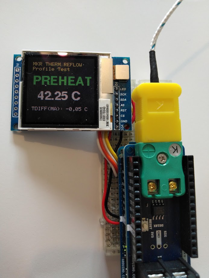
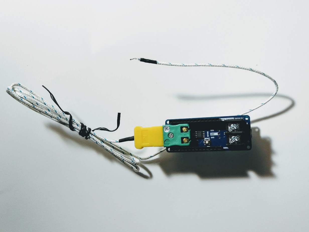
For the temperature measurement, I used an Arduino MKR1000 with a TFT screen and a MKR Therm shield. I added some bells and whistles to my firmware to tell me which reflow zone I was in and what my temperature gradient was looking like. For my testing phase I had a data stream going to the Serial Monitor at 1 second intervals, so I could then copy and paste this data into a spreadsheet for later analysis.
![]()
First temperature profile test
For my first temperature profile test, I wanted to see how fast the slow cooker could heat the PCB.
![]()
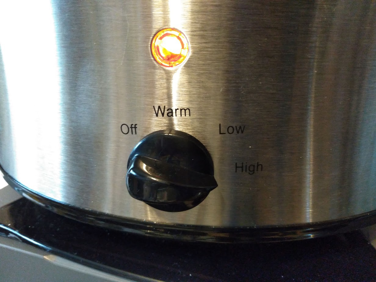
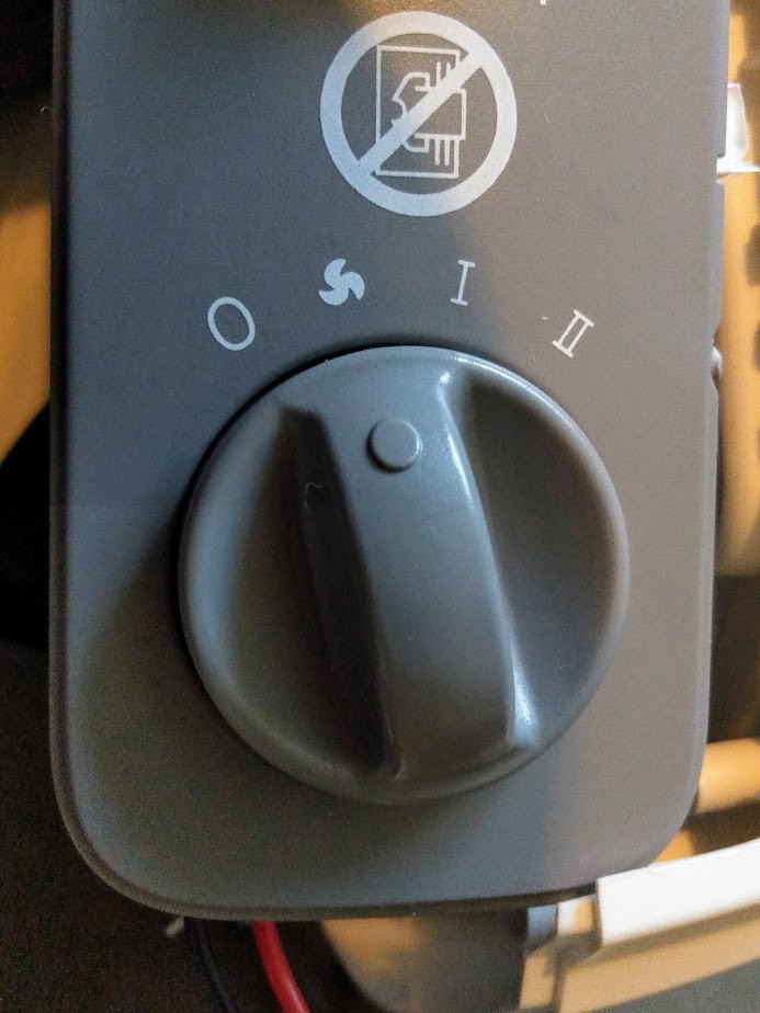
I used the high setting as this allows the temperature of the bowl to reach over 150 degrees C.
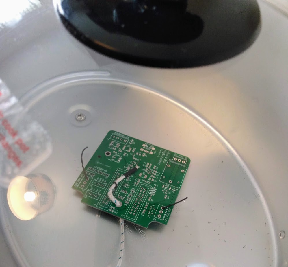
I placed the thermocouple onto an unpopulated or empty PCB and held it down with some wire making sure that the temperature probe was in the middle of the bai.
![]()
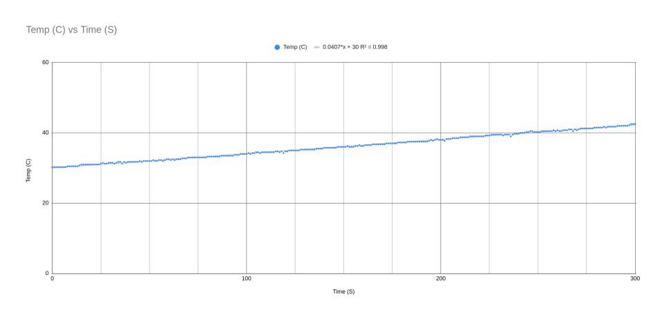
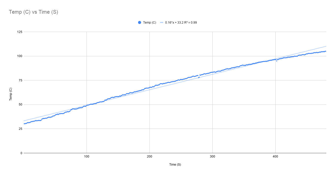
As can be seen by this chart, the heating profile achieved with the PCB inside the bowl was nice and linear but very slow.
![]()
Second temperature profile test
My first challenge was whether I could improve things just using the slow cooker. Then it dawned on me.
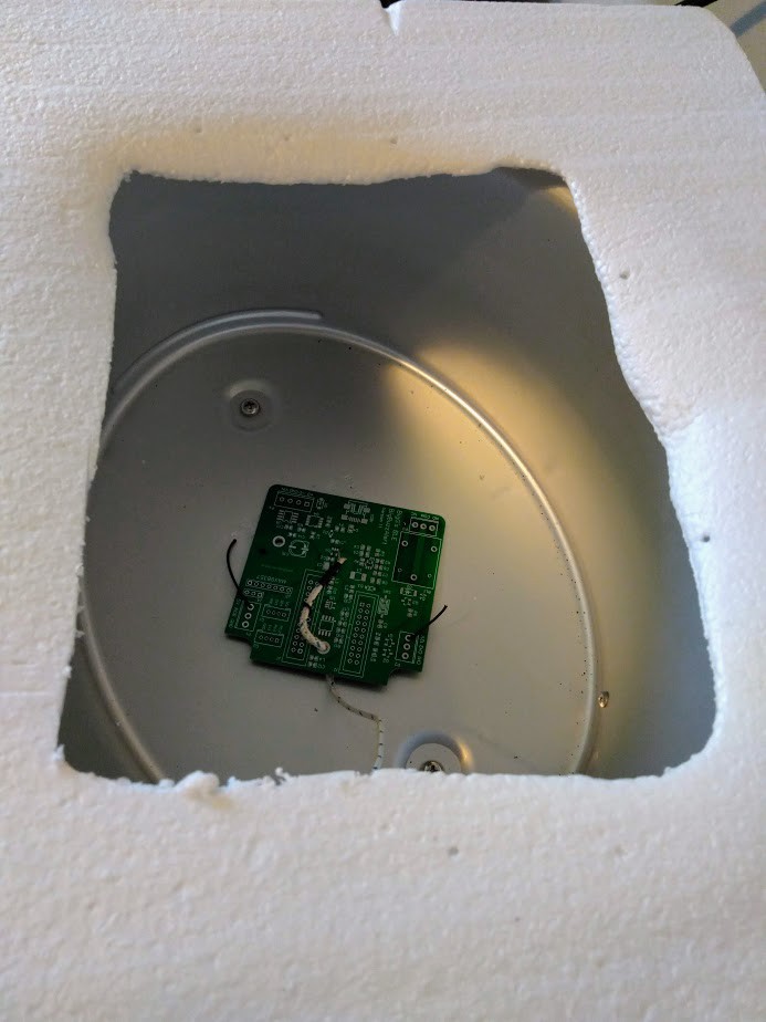
Who needs the bowl anyway as the heating comes through the aluminium shell. So, I removed the ceramic bowl and I placed the PCB inside the shell with the lid balanced on top (not quite a snug fit).
![]()
This provided a much much better temperature gradient. It took about 10 to 15 minutes to reach 150 degrees centigrade with the lid on.
![]()
This was an excellent start, in my opinion, as there is actually a science behind getting the whole PCB to reach the magic 150 degrees C in steady gradient for flux to do its thing and for "soaking" phase to kick in (I am using this PCB reflow reference as my guide).
Thus the slow but steady approach can be beneficial, if you are patient.
But I am not really the patient type so I immediately started looking at how this can be optimised through additional heating methods. This is where I thought the fan heater could be used with it's multiple heater settings.
Temperature profile tests using the fan heater
Unfortunately, my temperature measurements using the fan heater did not go as well as I hoped for.
![]()
Using the first heat setting, with the fan heater over the bowl, the temperature profile was not great at all.
![]()
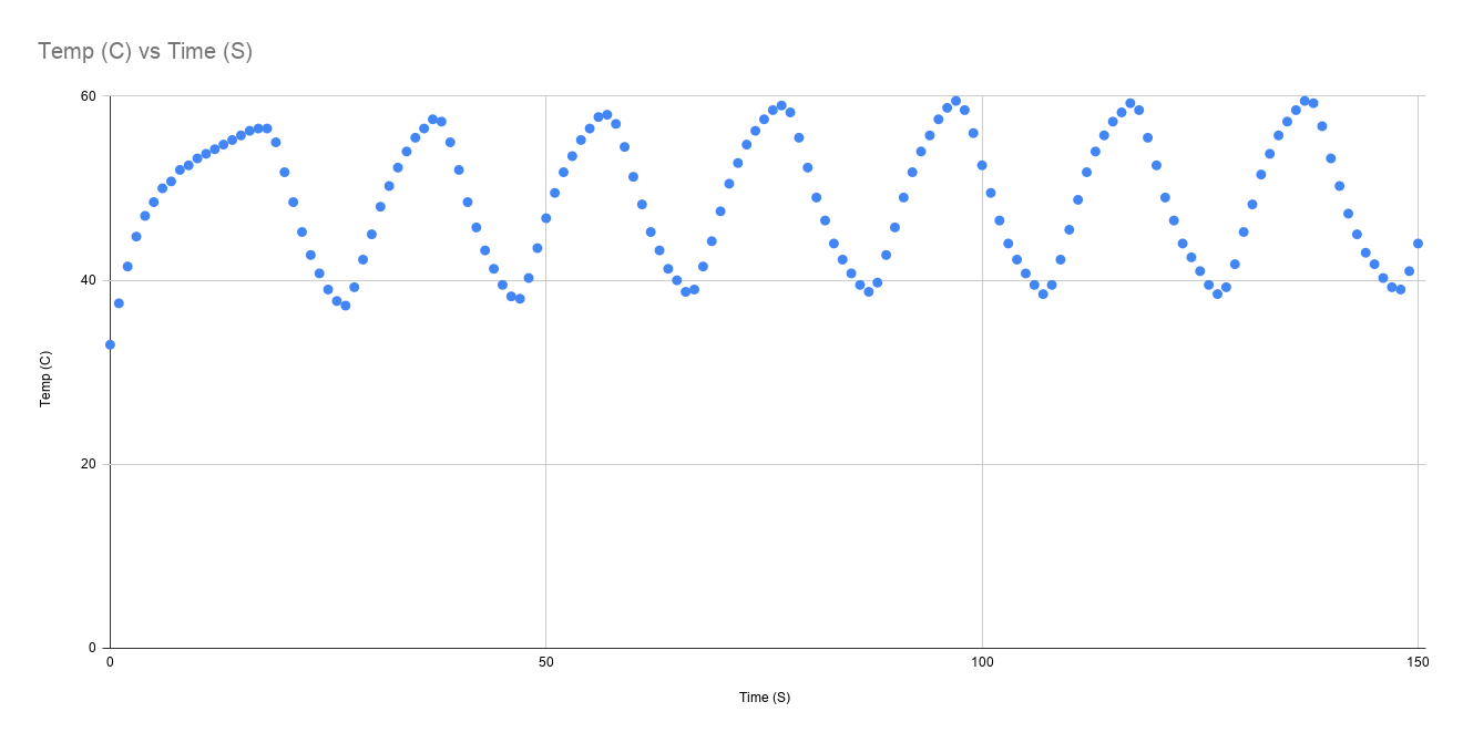
Then when using the maximum heat setting I had some improvement but this was not the profile I wanted at all. Clearly temperature control was kicking in.
![]()
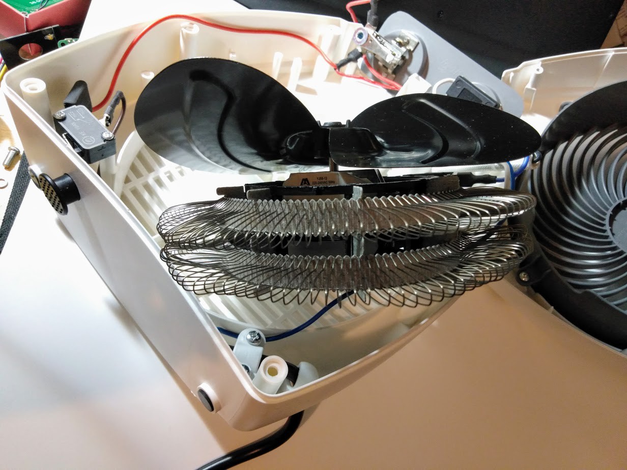
It was time to open up the fan heater and have a look inside.
![]()
![]()
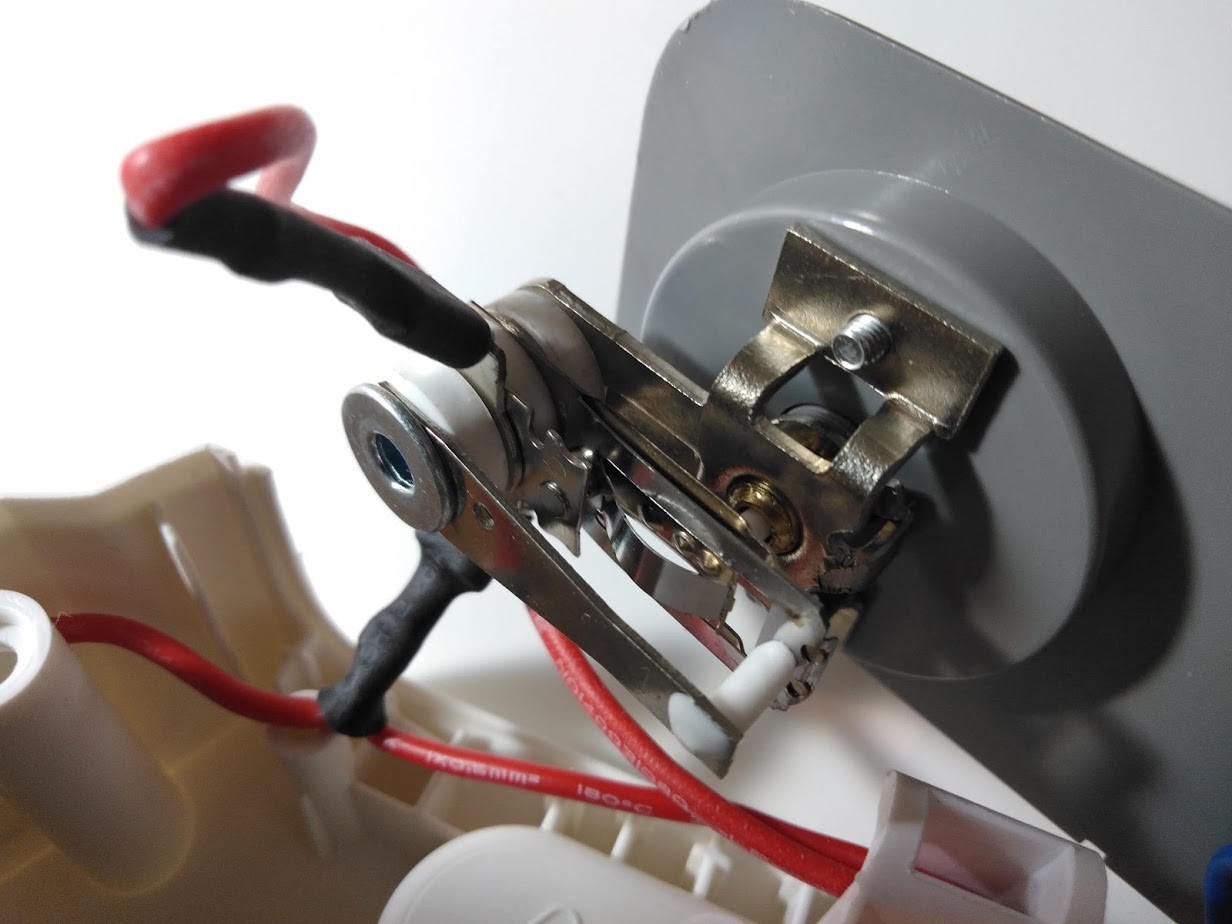
Inside the fan heater there was a mechanical type thermostat control mechanism. To solve my temperature fluctuation problem, I will have to remove this. For now, I am leaving this well alone.
So, it was back to the drawing board.Enter my light bulb moment
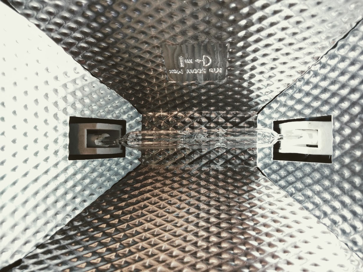
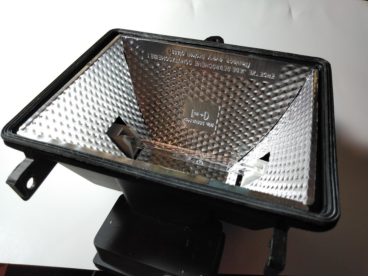
As I was rooting around looking for ideas, I spotted an old flood light I had in the shed. It was one of those that used a 400W halogen R7 type light bulb.![]()
I recalled that these halogen light bulbs were really good a giving off loads of heat, as the exterior casing got very hot. Doing some prelim online research confirmed that these type of light bulbs reach some impressive high temperatures the higher the wattage.
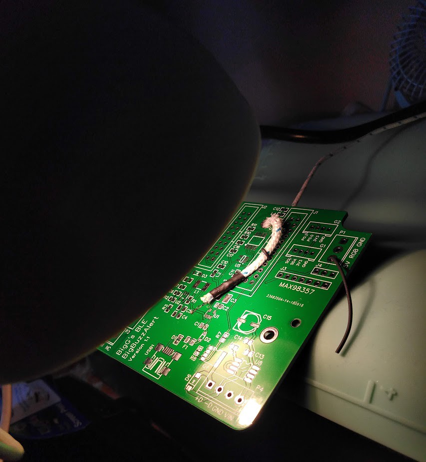
To ensure I got max heat with my flood light, I removed the glass covering.![]()
I then balanced it with some wood on top of the slow cooker and turned the light on (cooker remained switched off) and took some temperature measurements.![]()
The results were really encouraging.
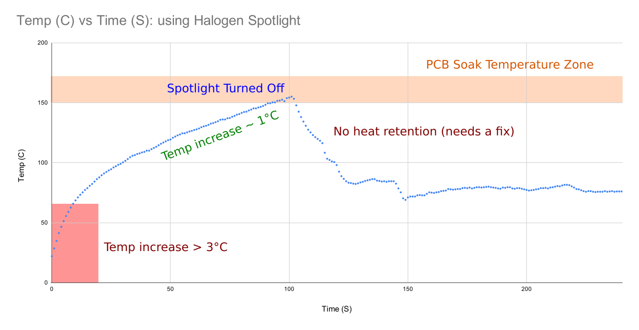
I am no PCB reflow expert so I am not sure what the implications are for the initial high temperature gradient (below 65 degree the temperature rise was about 5 degrees per second) but this eventually settled to a steady 1 degree per second rise all the way up to 150 degree, which is pretty darn good, in my opinion.
The problem now was that once I turned off the spotlight, the temperature plummeted as there was no means for heat retention.
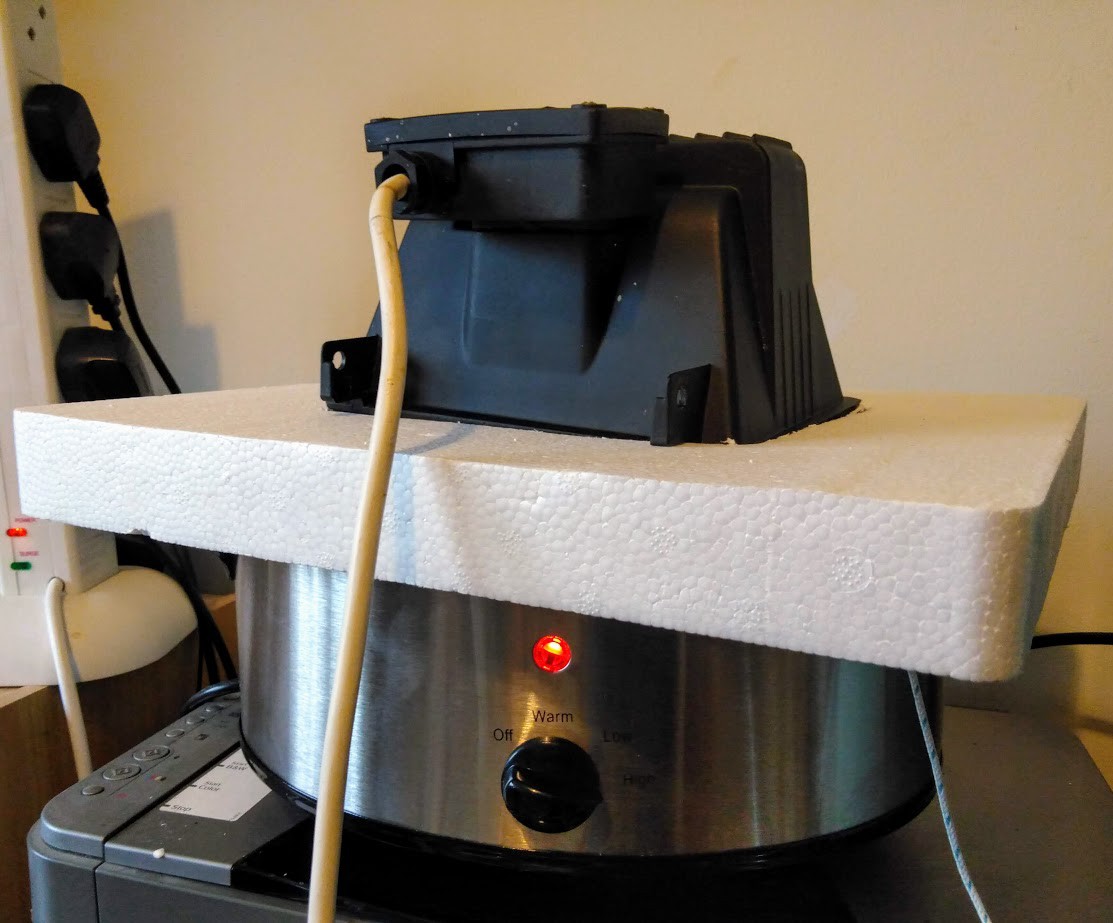
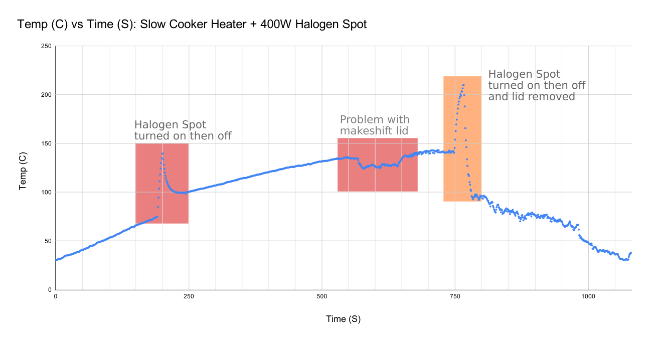
As a quick fix I used some polystyrene that was part of the slow cooker packaging. With my next temperature test I had both the slow cooker on max and then monitored what happened when I turned the light on.![]()
My makeshift lid set up worked pretty well until the temperature got above 120 degree C. The weight of the spotlight meant it started to give in as the polystyrene began to soften.![]()
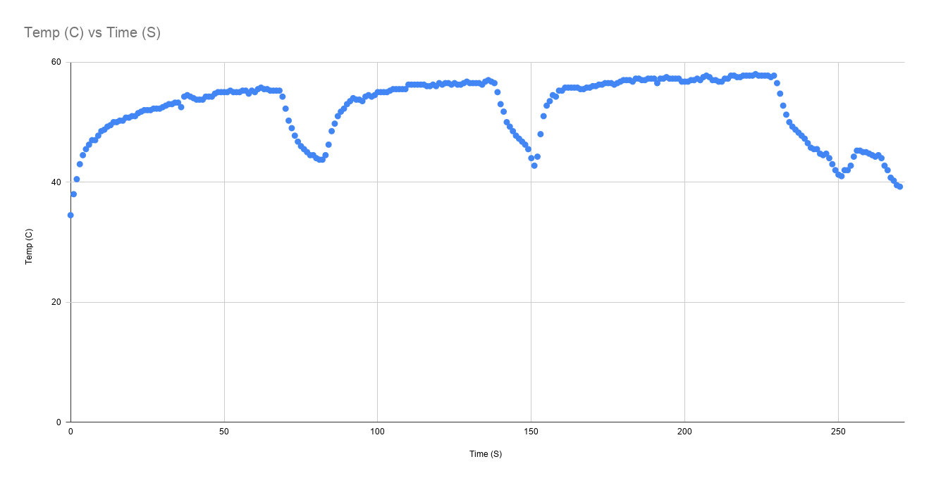
You can see how the halogen light and how the lid problem impacted the temperature profile.![]()
The really good news is that combined it can work. If I left the halogen light off until the soaking period has ended, I can then turn the light on to give that boost to reach the solder reflow temperatures required.
Summary
So, not bad for a first run using this new simplified set up of slow cooker and halogen light for added heating.
Together, the combined cost of $30 is pretty good - that is, $15 for the slow cooker and about $15 for a 400W halogen flood light... and the polystyrene comes free with the slow cooker packaging (although it only works once). The fan heater can wait until a cold winters day where it may get some use again. As for the silicon baking mat... hmmm, not sure yet. All I know is that I should've gone for the baking/oven mitts instead of the baking mat, as those PCB's take a good while to cool down.
My next steps is to play around with the lighting setup to optimise and to come up with a better slow cooker lid come light fitting. I found online that you also purchase infrared R7 light bulbs, if you want to spend more - this will then remove the bright light. For now, I am looking to use a lower wattage light bulb and then maybe use two of them for more finer temperature control. I can then look at adding in either a relay or SSR to help automate the light on and off for further temperature control too.
-
What does a Silicon baking mat have to do with my reflow project
07/05/2020 at 21:02 • 0 commentsBetter to be cautious than having a cracked ceramic pot. Most of the online literature about slow cookers tell you not to put the ceramic pot in the oven etc.
As the duration of the reflow heating profile is quite short (about 5 minutes) my view is that it is better to treat the bowl like a glass bowl, which if subjected to a high temperature shock will crack.
To mitigate this cracking risk, I have been searching online for some thermal aids to place inside the bowl.
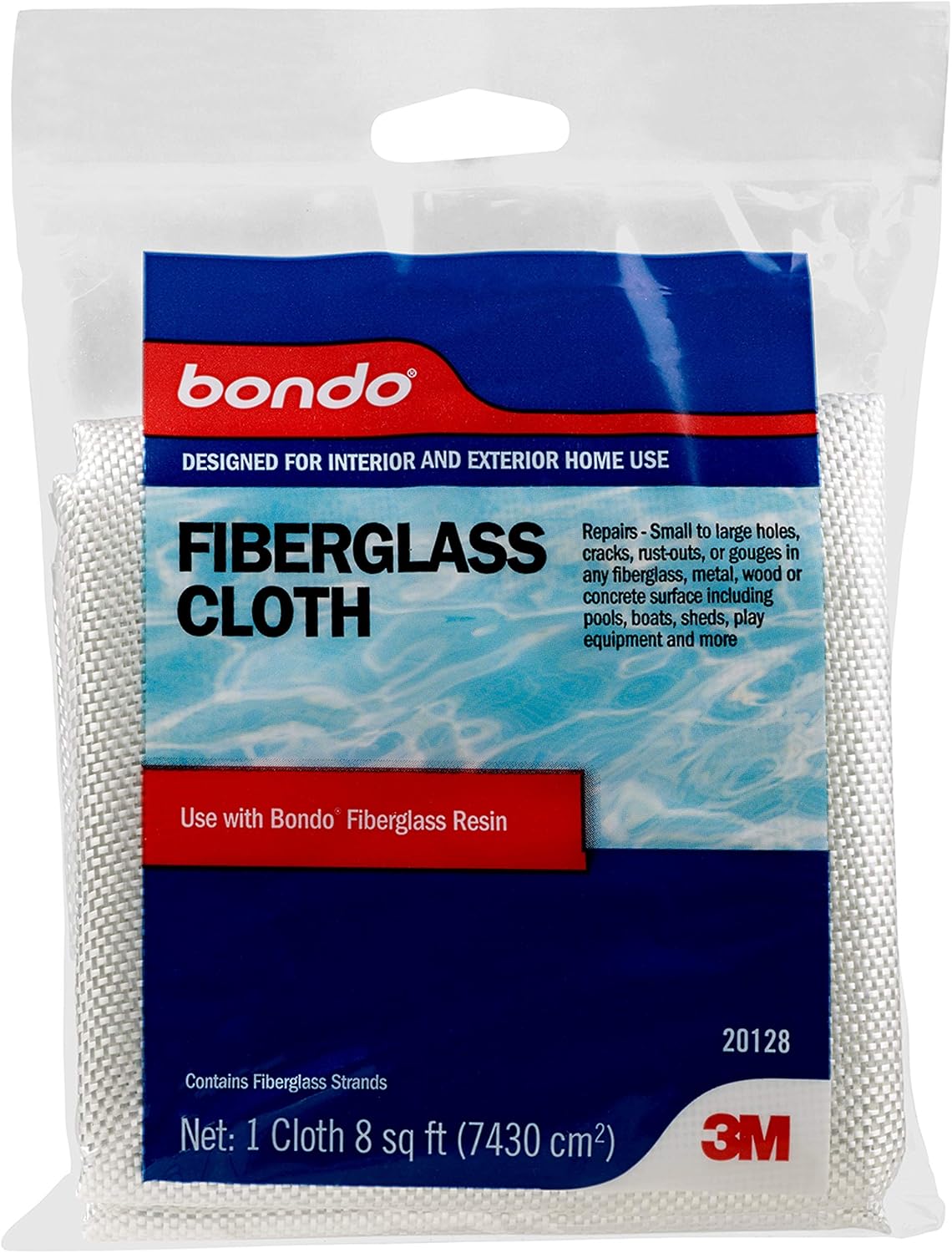
The first idea I thought of was fibreglass woven fabric, which can withstand high temperatures. You can readily find these sort of products on Amazon. Here is one such example:
![]()
https://www.amazon.com/Bondo-20128-Fiberglass-Cloth-sq/dp/B002JRGOT8
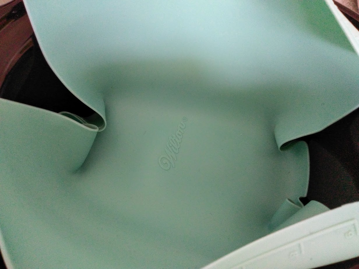
The next product I thought of, which could offer some thermal assistance was a silicon baking mat. These too can be readily purchased online or can be found at places like Ikea or any place specialising in baking products. I know Amazon stock some great ones which even include glass fibre.
I found this silicon baking mat at a local store for less than $10.
![]()
Finally, another off the wall product I found online on Amazon where these silicon oven mitts or gloves. I thought these would provide even better thermal insulation if, in the unlikely event, it is needed.
My next step, is to now set up some temperature testing as my k-type thermocouple probes have arrived in the post as these fit my Arduino MKR Therm Shield, so I'm ready to go.
![]()
If the temperature of the ceramic bowl rises much above 180 degrees C, I may then add in further thermal insulation, such as foil under the silicon mat (the reason I did not simply use foil is that it creates too much heat reflection, which I do not want) or purchase those silicon oven mitts.
-
A fan heater has been procured!
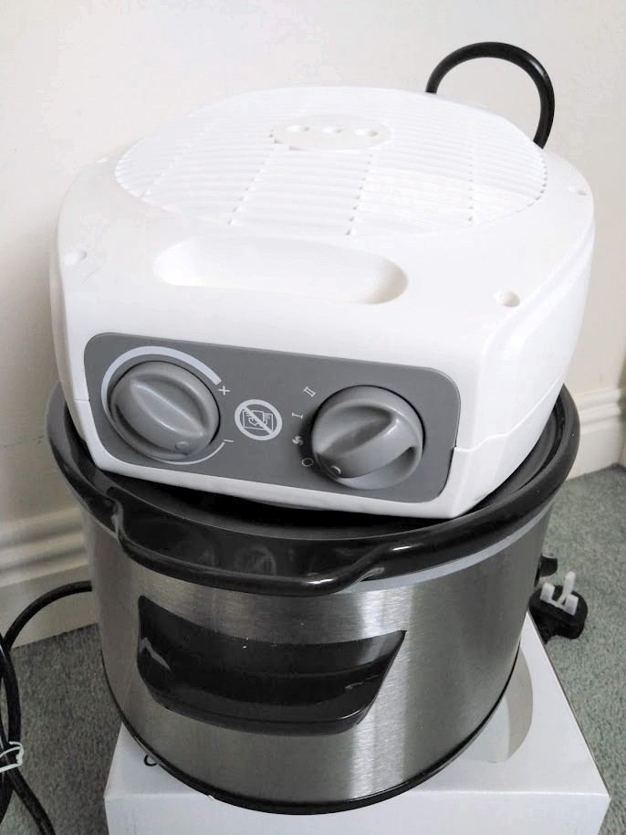
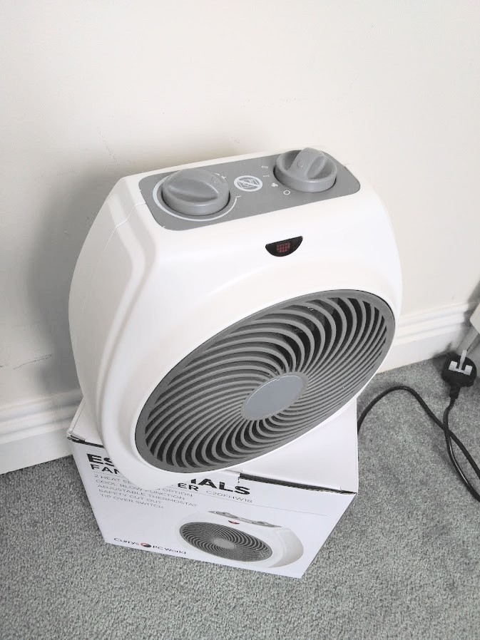
06/12/2020 at 15:54 • 0 commentsI've just purchased a new fan heater for $12. It may be overkill in terms of size or it may end up delivering a lukewarm result. Will wait and see. The nice thing is that it fits on top of the slow cooker (no wobbles so won't topple over).
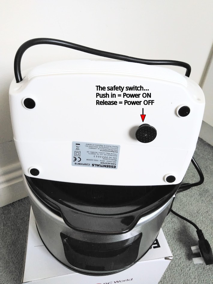
Another benefit with this fan heater is that it potentially can be hacked without burning the house down. At the bottom of the heater there is a cut out switch which keeps power on if pressed in or switches power off if released. Just need to find the right relay to replace the tamper/kill switch.
Next part of research will be evaluating temperature profiles based on heat settings and fan speed.
![]()
![]()
![]()
Using a Slow Cooker to reflow your PCB's
Repurposing a low cost slow cooker to provide a simple (and maybe a more energy efficient) way to reflow PCB's