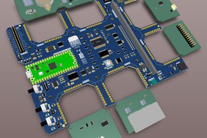
This is the smallest system board based on STM32F1032F205VE and carries ST-LinkV2.1, which is also compatible with STM32F103Vx and STM32F407Vx.
Step 1: Characters
New PCB sample by JLCPCB by $2 for 5 pcs.
1 Optimize circuit design by EasyEDA, now all GPIO map to at most 1 peripheral, no IO conflicts
2 Optimize circuit layout
3A set of power pins has been added to power the peripherals RBG lamps now use an op-amp drive (voltage following mode) to reduce the impact on IO port output hf signals
4 Add EEPROM chip (AT24C02 256Byte) for the fast storage of application data.
5 You can eliminate the need to use internal Flash to simulate EEPROM and reduce wear and tear on internal Flash.
6 Spi-flash was added to meet the need for persistent data storage.
7 The LCD interface was redesigned to retain support for most of the finished modules on the market while improving scalability. It is now compatible with 16bit and 8Bit 8080 LCD screen modules.
8 Both EEPROM and SPI-Flash can be turned on or off with jumpers Fixed some bugs and now can better support STM32F103Vx and STM32F407Vx.
9 Mounting holes are added to facilitate positioning and mounting.
10 Optimize screen printing for clearer hints.
Step 2: MCU Characters
The board looks like after free SMT service from JLCPCB
1 32-bit ARM Contextm3 core, maximum 120MHz main frequency
2 512KB ROM + 128KB SRAM
3 14 timers
4 Three 12-bit AdCs and two 12-bit DACS FSMC function
Step 3: System Board Characteristics:
1 Onboard ST cc-link V2.1
2 Micro-USB interface, 500mA over stream protection
3 The BOOT0 switch USES a toggle switch, and there is also a toggle switch to switch the built-in/external ST-Link
4 Four status indicator LEDs are onboard, and one co-positive RGB LED is programmed
5 An interface compatible with most small display modules
6 Micro - SD interface
7 USB - FS Three keys, one for reset, the other two for user keys
8 0.47F ultracapacitor, supplying power to RTC
Step 4: Schematic
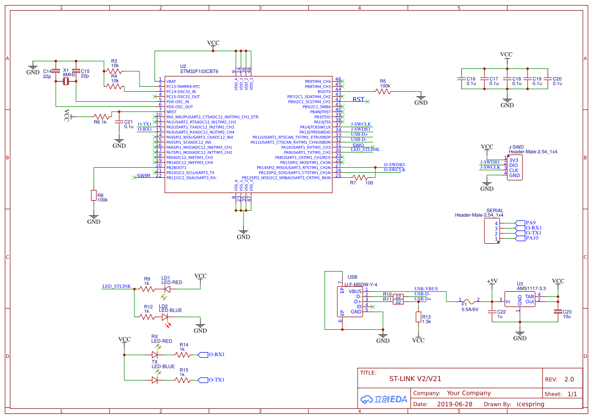
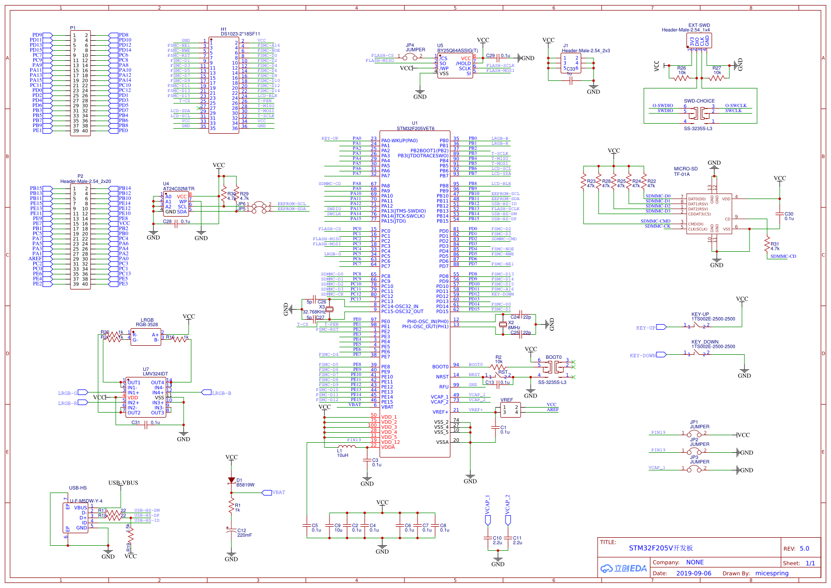
Note: : Another ST-Link is needed to write ST-Link's Bootloader for STM32F103CBT6 on the board. The firmware is in the attachment. After downloading and burning the firmware, the on-board ST-Link function can be normally used after st-Link Utilities is upgraded.
Step 5: PCB File

Complete File Enclosed, if you have any interest to make comments, please feel free to leave a message here.


 Sander van de Bor
 rob
rob
 Luke Valenty