Pierre-Loup M.
-
Making choices, validating them.
06/17/2020 at 10:04 • 0 commentsThe donor fame being chosen, half of the geometry is settled. Then comes the time of choices.
What length do I need, or want, for the cargo bay ?
What width ?
Do I want to go easy with a large, straight central beam and secondary beams on the side ?
Or should I build something a bit more complex with two beams on sides, and spars in between ?---------- more ----------
First for the length : commercial cargo bikes come with a cargo bay ranging from 40 cm to almost 1 meter. 40cm seems too short for the use I plan, 1 meter is far too long. The problem is that it of course adds to the overall length of the bike, thus making more difficult to store the bike. I've set the cargo length to 66cm, which should be a a good compromise between cargo size and overall length, with a total wheel to wheel length of 246cm.
Then the width. A rule of thumb is that the cargo should not exceed the size of the handlebars. It makes handling easier : if the handlebars passes, then goes the bike. The one I have on the MTB is almost 60cm wide. More than I need, so I've set it to 45cm. Why 45 ? it gives a round 40cm for the cargo floor. :)
Then the question of beam configuration. As said above, a unique central beam is probably easier. It's in the symmetry plane, and if your beam is straight, so should your bike be ! But a central beam needs lateral beams to hold the cargo floor, which adds to weight. With a central beam I also have the feeling that lateral torsion could be an issue.
On the other hand, two lateral beams give both the longitudinal and lateral strength and hold the cargo floor. They can be smaller than an unique central one, and I also find them more pleasing to the eye. While most DIY cargo bikes use a central beam, most commercial ones use two lateral. Of course triangulation will be needed at the rear to keep constrains low with the frame junction.
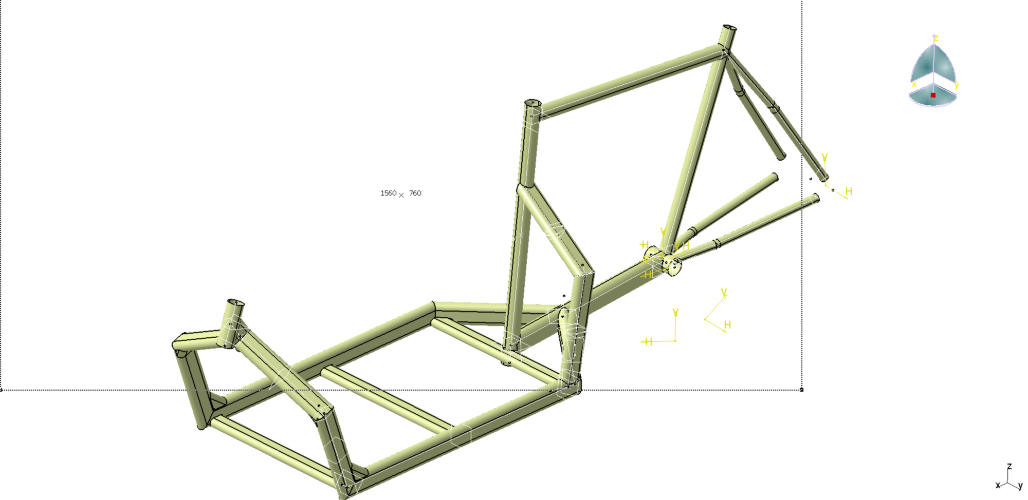
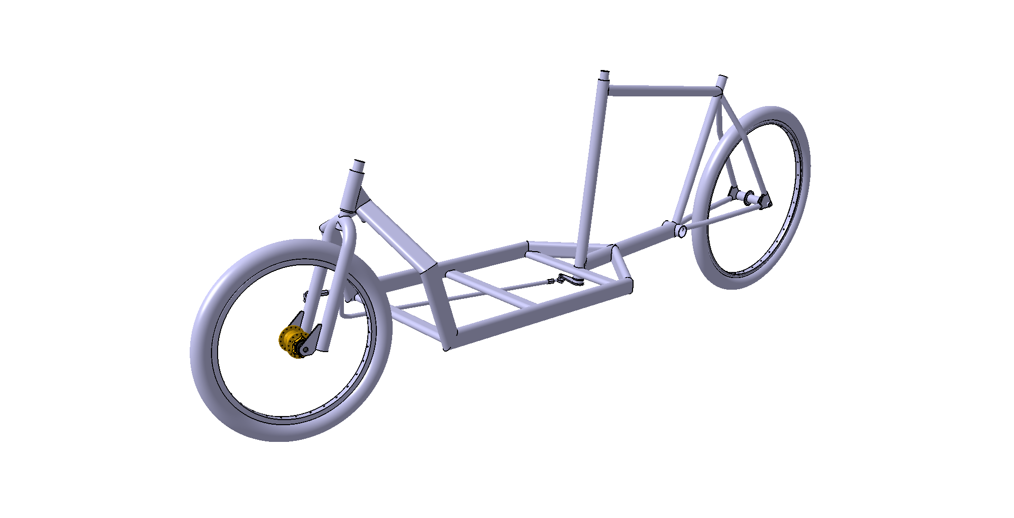
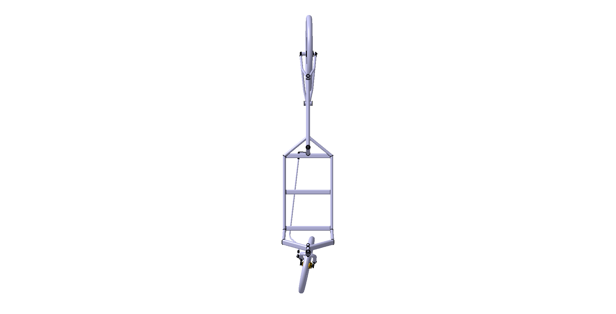
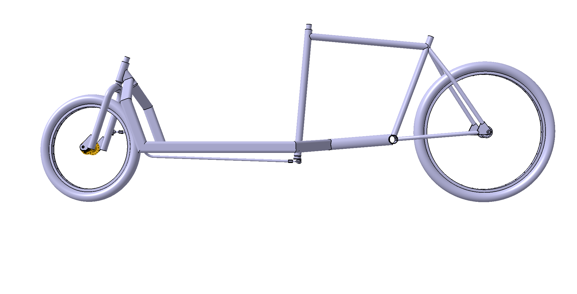
So here is the design I came up with :![]()
![]()
![]()
Some design choices are not definitely set yet. I don't what the handlebars tube angle will be. Here it's 85°. I suppose this value is mainly dictated by the use made of the cargo bay. For carrying children around it would make sense to have it a slacker angle. For cargo a 90° should be perfect, so a crate can sit on the tube. In between values are mainly for beauty, I think.
The other angle that could vary is the direction (fork) tube angle. On most cargo bikes it's somewhere around 75°. This angle conditions the stability and handling of the bike, but is linked to the wheel size and the offset of the wheel from fork. I need some more readings.
I was lucky enough to find a medical bed at the waste collecting center, just an hour after I bought the second bike. Its main frame is made of 50x25mm, 2mm thick rounded tube, and the secondary frame is 40x20mm, 2mm rounded tube. I was really pleased to find this, it will be both nicer than square tubing and easier to work with than round. And I have enough to have spare when the bike will be finished, or if I miss a cut...
Intuition tells that this tube should be sufficiently strong, but sometimes knowing is better than guessing. I've used the CAD software to estimate how this design would handle under load. I've used values unlikely to happen in real life, like 150kg equally distributed on the three cargo spars, plus 90kg on the saddle tube, plus 10kg on the handlebars. After a first run, I wanted to know how it would behave with a lateral load (e.g. the bike being held at an angle while loaded). I thus added a 20kg lateral load on the handlebars on top of every previous loads.
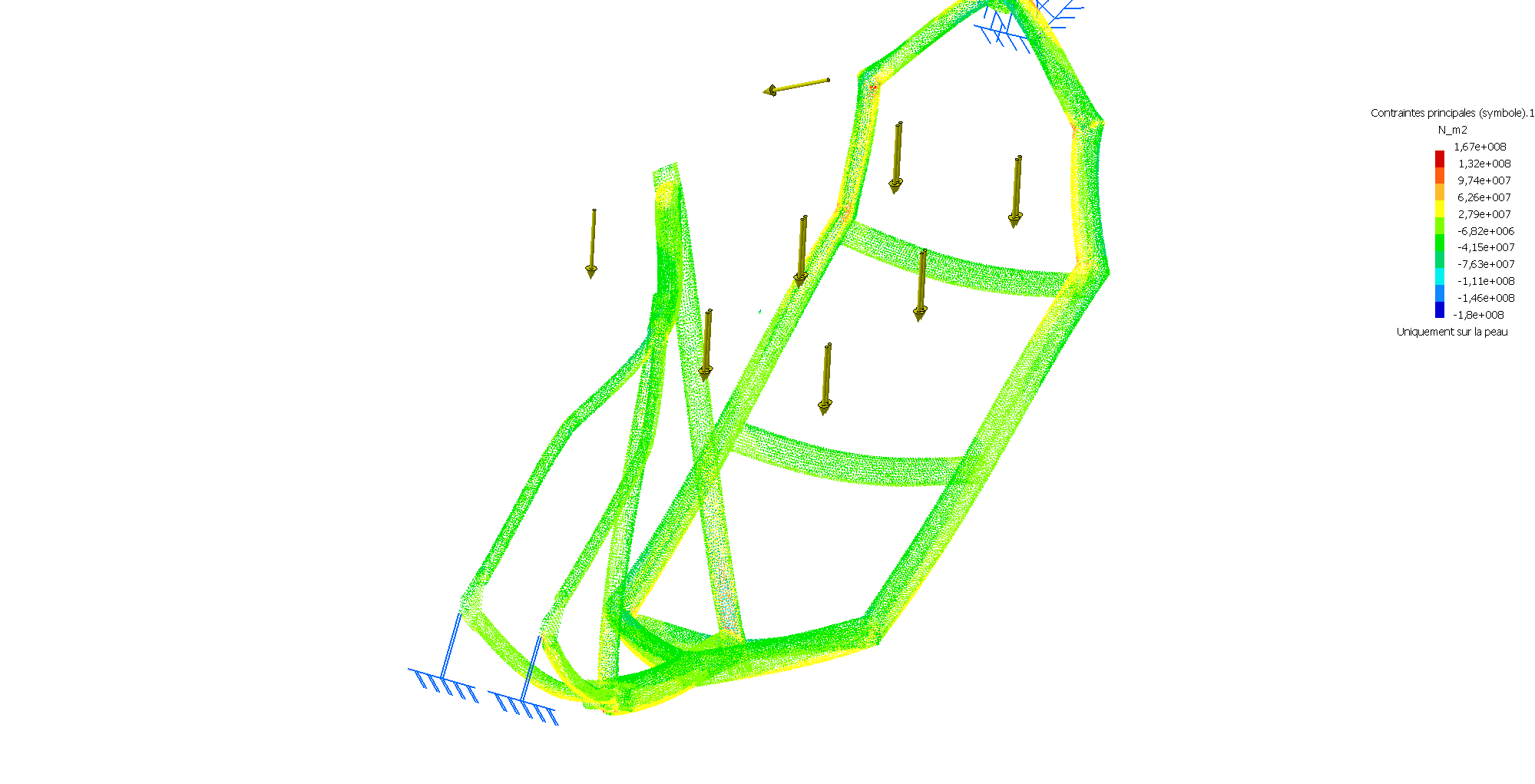
Here is the result in terms of constraints :![]() Keep in mind that the deformation showed is way exagerated, so the constraints are made obvious.
Keep in mind that the deformation showed is way exagerated, so the constraints are made obvious.
The max constrain on the frame is around 165 MPa, which is at least 30% under the elastic limit of a basic steel. These max constrains are only reached at the linkages of the top frame, where tubes are soldered end-to-end. So there will be gussets added here to limit this constrains.
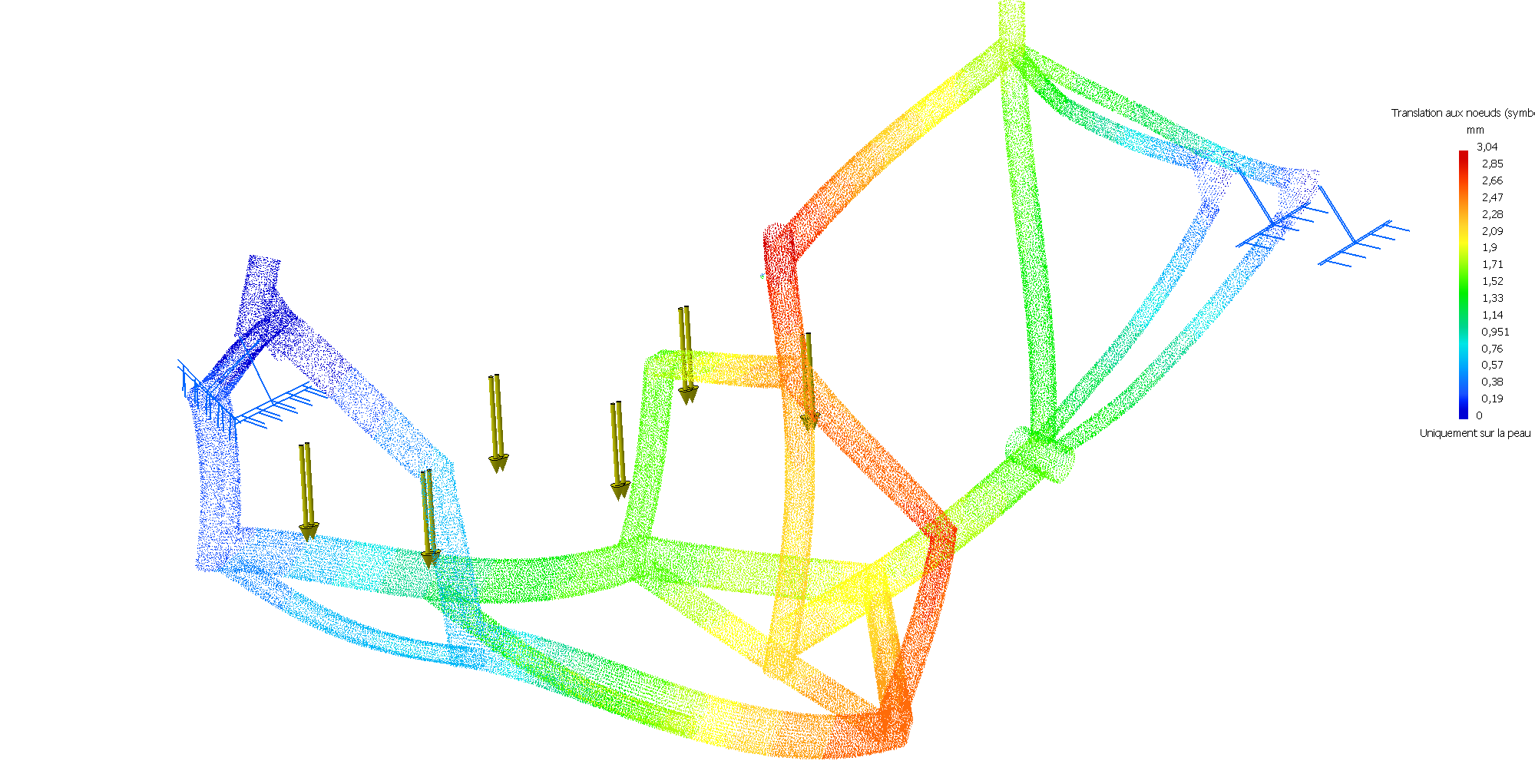
Here is the result in terms of displacement :![]() The max translation is 4,5mm at the top of the handlebars tube. It maybe too much (but I don't really know how a normal bike under load can deform, so I've added triangulation around this tube. The results are better :
The max translation is 4,5mm at the top of the handlebars tube. It maybe too much (but I don't really know how a normal bike under load can deform, so I've added triangulation around this tube. The results are better : ![]()
Note 1 : the lateral translations are probably not realistic : when you push on a bike, the wheels follow, so it's unlikely the frame will be ever laterally constrained like this.
Note 2 : the constraints should even lower, I've just realized the while have been designed with a 1,5mm tube thickness, where the front frame will have 2mm tube.
To be followed... -
The first step...
06/16/2020 at 17:48 • 0 comments... is to find donor bikes. Two are needed. One with 26" wheels for the rear frame, and one with 20" wheels for the fork and front wheel. Almost all cargo bikes available and self-made use these sizes. On the trike I had a 700 wheel at the back, and two 26" at the front, and it was a bit to high, thus less stable.
I've tried too find an electric bike for the rear frame, that would have been nice to go with a motor from the beginning to help, but every bike I found used was made with aluminium frame, that most people (including me) cannot solder. So the next choice is to use a mountain bike, which is made to be strong. On this bike we keep the rear wheel, the crank, the frame, the direction pivot, the saddle.
The second bike is for the front pivot, the fork and wheel. With a 20" wheel, the obvious choice is a BMX, which are strong bike too.---------- more ----------Both bikes where bought for 30€ each.
The first step, prior to dismantle bikes, is too measure them. Lot of people go with a global schematic and adjust while doing, I prefer to have a globally set design before to start. so, measurements. The only tool used here is a measure tape. It's fun to see that every measure is round, except from the tubing sections.
![]()
From here I start by drawing a sketch in my favorite CAD software. In this sketch are just included the points of the geomerty, viewed from side. From these points is drawn a wireframe, and then each section is drawn to build the volumes. It can be quite messy with all the references planes needed, and all the sketches for sections !![]()
There are several things that are made easy by using a cad software :
Every tube junction can be easily exported as a developed shape.
The global weight can be accurately estimated.
The needs for tubing can be precisely calculated.
And, last but not least, the deformations and constrains of the frame can be tested under load ! I'll come back to this later. -
A word about the cargo trike !
06/15/2020 at 19:47 • 0 commentsIt has been a relatively quick project, but ambitious one for me, as I had never worked with steel before. Fortunately, my sister's husband was a metal worker, and showed me how to use MIG, and let me use their professional gears...
![]()
 Keep in mind that the deformation showed is way exagerated, so the constraints are made obvious.
 The max translation is 4,5mm at the top of the handlebars tube. It maybe too much (but I don't really know how a normal bike under load can deform, so I've added triangulation around this tube. The results are better :