Details about this project are simple (at least on this moment) build a delta robot using:
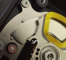
- Three or four broken HDD that at least his actuator arm works.
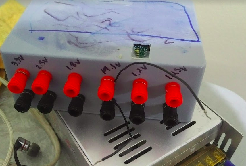
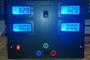
- My humble Power supplies.
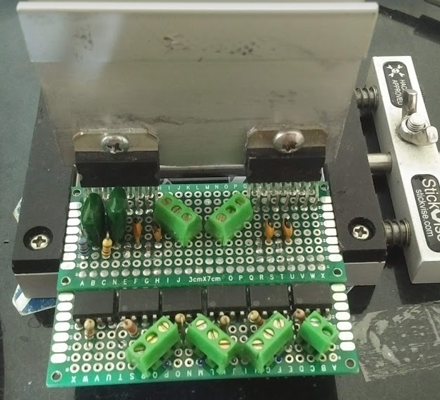
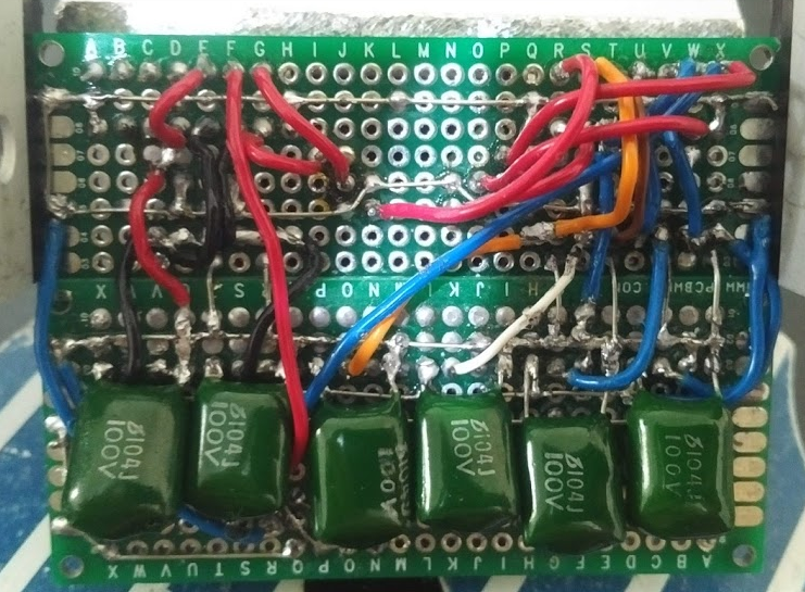
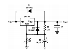
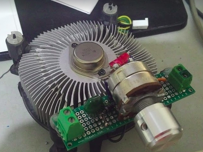
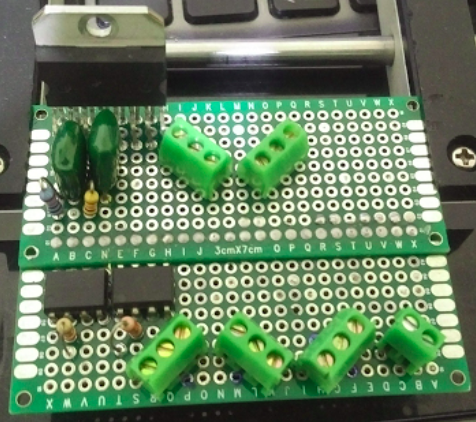
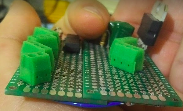
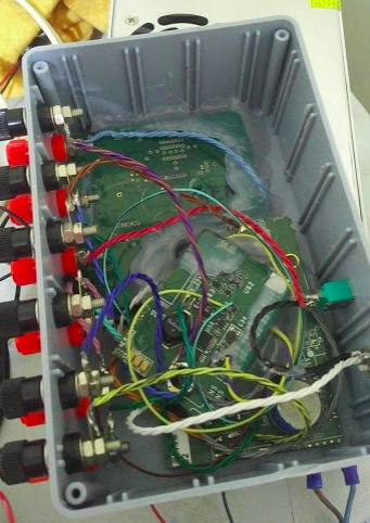
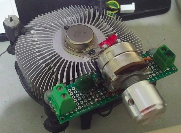
- Power stage, build from my parts bin.
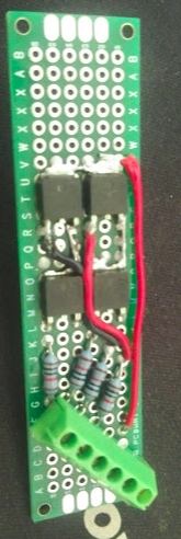
- optical isolation, from my parts bin.
- Microcontroller, also from the same parts bin a never used XMOS startkit.
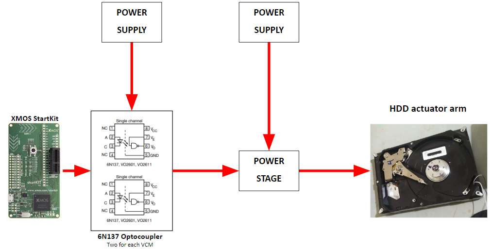
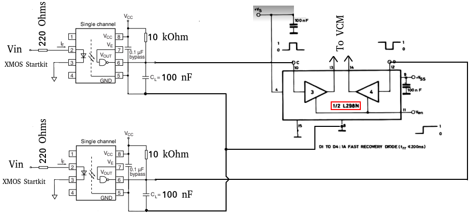
So this is vaguely the diagram that I have on mind for one HDD actuator arm, I dind't define what power stage I will be using because on my parts bin I have different options and I have to analyze what fits better on this, when the power stage and the arrange of power supplies are defined basically will be the same diagram repeated three times.
First I need to work on:
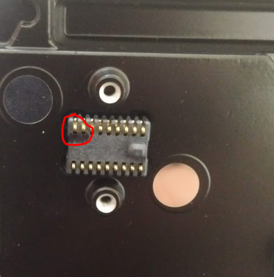
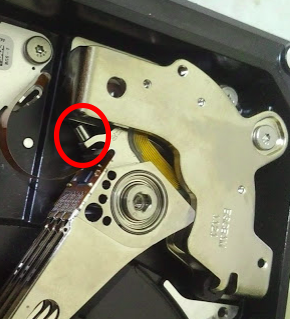
- (DONE) Test the four HDD actuator arm voice coil motor (VCM).
- (DONE) Analyze how the power stage will be.
- (DONE) Test the 6N137 opto isolators from my parts bin to check if they are still alive.
Then I can move on the next steps:
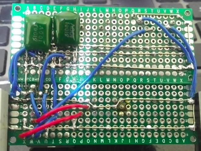
- (DONE) Build the circuit for only one power stage.
- (DONE) Build opto isolation for power stage from last point.
- (DONE) Make tests (without XMOS).
- (DONE) If test are OK then repeat the first three steps two times.
- (WORKING ON IT) Do more test (withouth XMOS).
- Make "hello world" tutorial for the XMOS startkit.
- When I have a decent knowledge start making a simple program to test all the electronics together.
- Try to make a decent mechanical structure to mount the three HDD actuator arms.
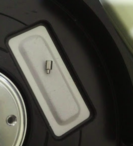
- Try to do the needed mechanical adaptations to each HDD to only left the actuator arm.
- Connect all and do more test.
- Start serious programming to make that my delta robot do delta robot related stuff...
The 8 and 11 will be what I think more weighty part of all the project, because involve reading and learning about inverse kinematics and many other stuff, so I can know how to put all togetheter to obtain the max movement space, and how to control three arms correctly.
The main goal is: go far as I can.
***NOTE: When this project move to a more advanced state I will do a complete schematic as at this moment isn't suitable make one because even some parts of the project can change a lot...


 SUF
SUF
 Brian Lough
 KingOfKYA(Travis K. )
 Patrick Van Oosterwijck
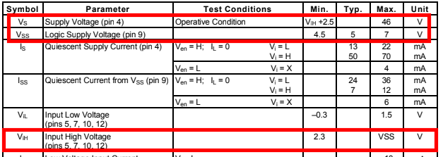
I don't see any use in the opto isolators. You have both GNDs connected - which is a good thing anyway. It's better to have a solid GND and not different ones. You somehow use them as level converters which is unnecessary anyway. You even marked the V_ih in the datasheet excerpt in red: min. 2,3V. So you can control it with 3,3V CMOS logic signals.