-
Initial Testing
06/30/2020 at 16:04 • 0 commentsI finally got out away from the city and was able to do some testing. For this, I mounted the star tracker on a small, but stable tripod. I used my Sony Nex-6 mirrorless camera with 210mm telephoto lens. No celestial objects were focused on in particular, as this early testing was focused on function first.
Alignment ChallengesSince this design is a simple, "dumb," single-axis tracker, it must be well aligned to work properly. Effectively, the axis of rotation of the tracker must be aligned with the Earth's axis of rotation. Then, the tracker can rotate at 15deg/hour and counteract the Earth's rotation. If not properly aligned, star trails will still be an issue.
This is certainly an area of possible improvement. I used a compass app and a star app to determine where to point the system. In the northern hemisphere, pointing the axis at Polaris does a fairly good job. However, without "sights" on my tracker, this is fairly difficult.
Learning Settings
The other challenges I faced were settings related. I had never used my telephoto lens for astrophotography before, and it raised some challenges. The most significant was focusing. Unlike a DSLR where you can look directly through the optics to focus, mirrorless cameras provide a rendered view through their electronic viewfinders (EVF). In dark situations, this doesn't work well, so focusing can be difficult. You can counteract this somewhat by focusing on a very bright star, planet, or the moon, where the EVF will be able to show the object. However, my telephoto lens has electronic focus, and the focus ring is not physically controlling focus. It is basically a knob that can continually rotate. This makes it very difficult to finely tune the focus and to maintain focus.
I also spent some time adjusting exposure time, ISO, and other settings to get decent amounts of light.
Camera Vibration
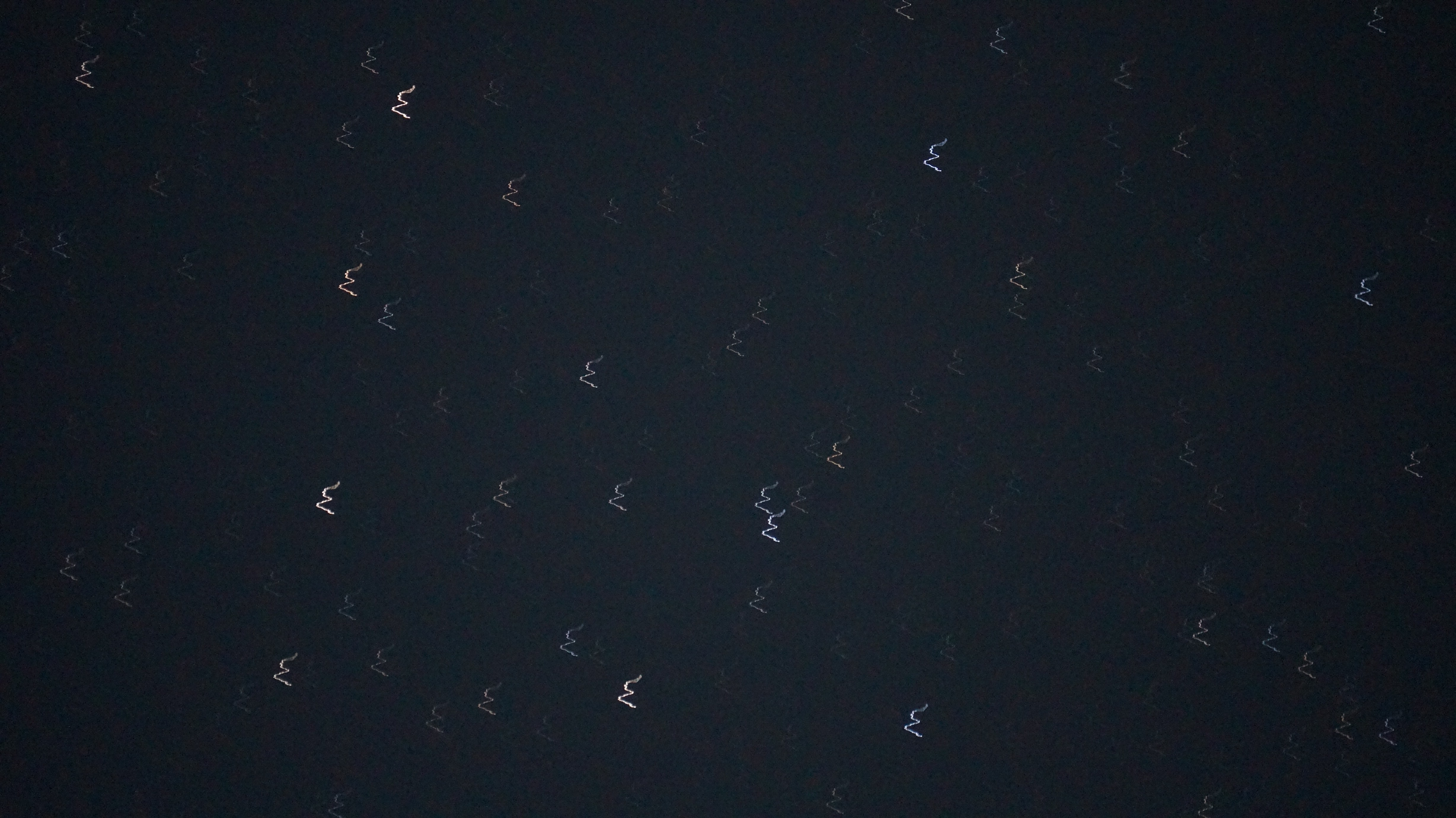
I had set my camera to wait 2 seconds after pressing the shutter button to begin the image. This is to avoid moving the camera while pressing it. It seemed this is not long enough. My setup does not seem stiff enough, so it deflects a noticeable amount. This is seen in the star trails that are not straight, but zigzag due to vibrations. Moving to an IR trigger would help a lot.
Example ResultsThese photos are not great, but were a good lesson in the challenges of this setup. They are all unedited from the camera.
Some of the images show very clear vibration of the camera. It is unclear yet if this is from pressing the shutter button, or actuation.
![]()
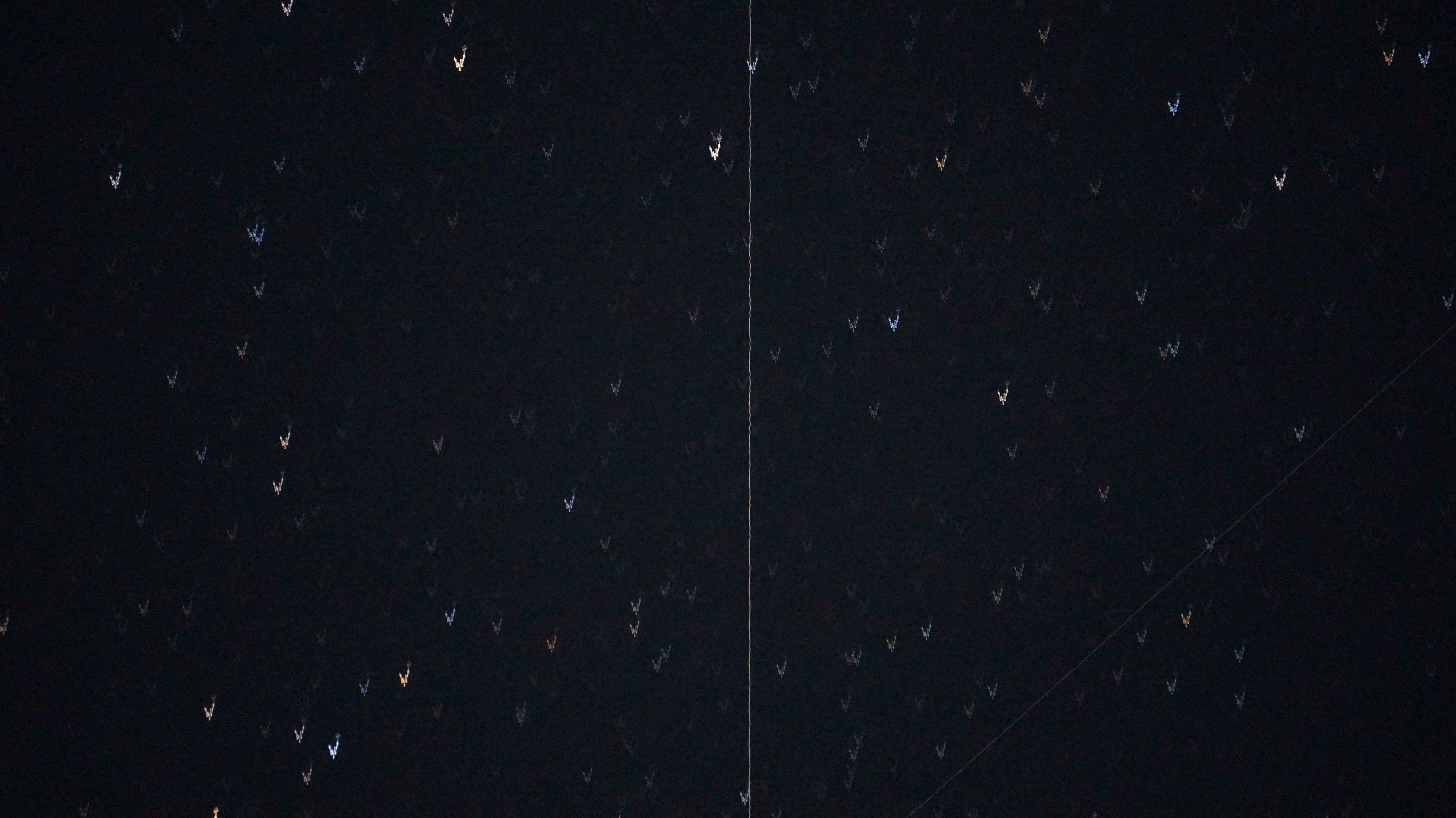
I also caught a satellite coming across the FOV, with vibration still visible here.
![]()
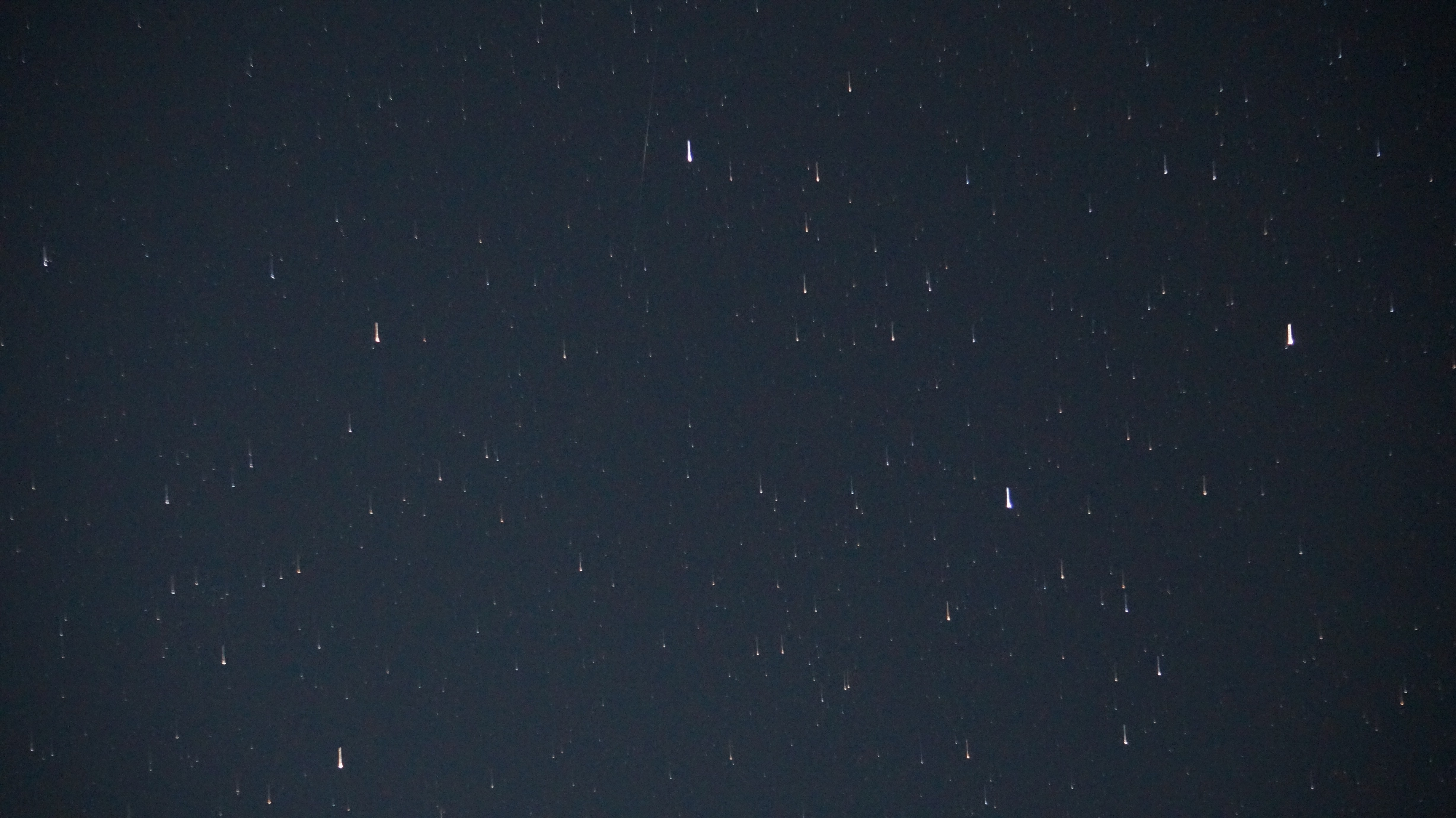
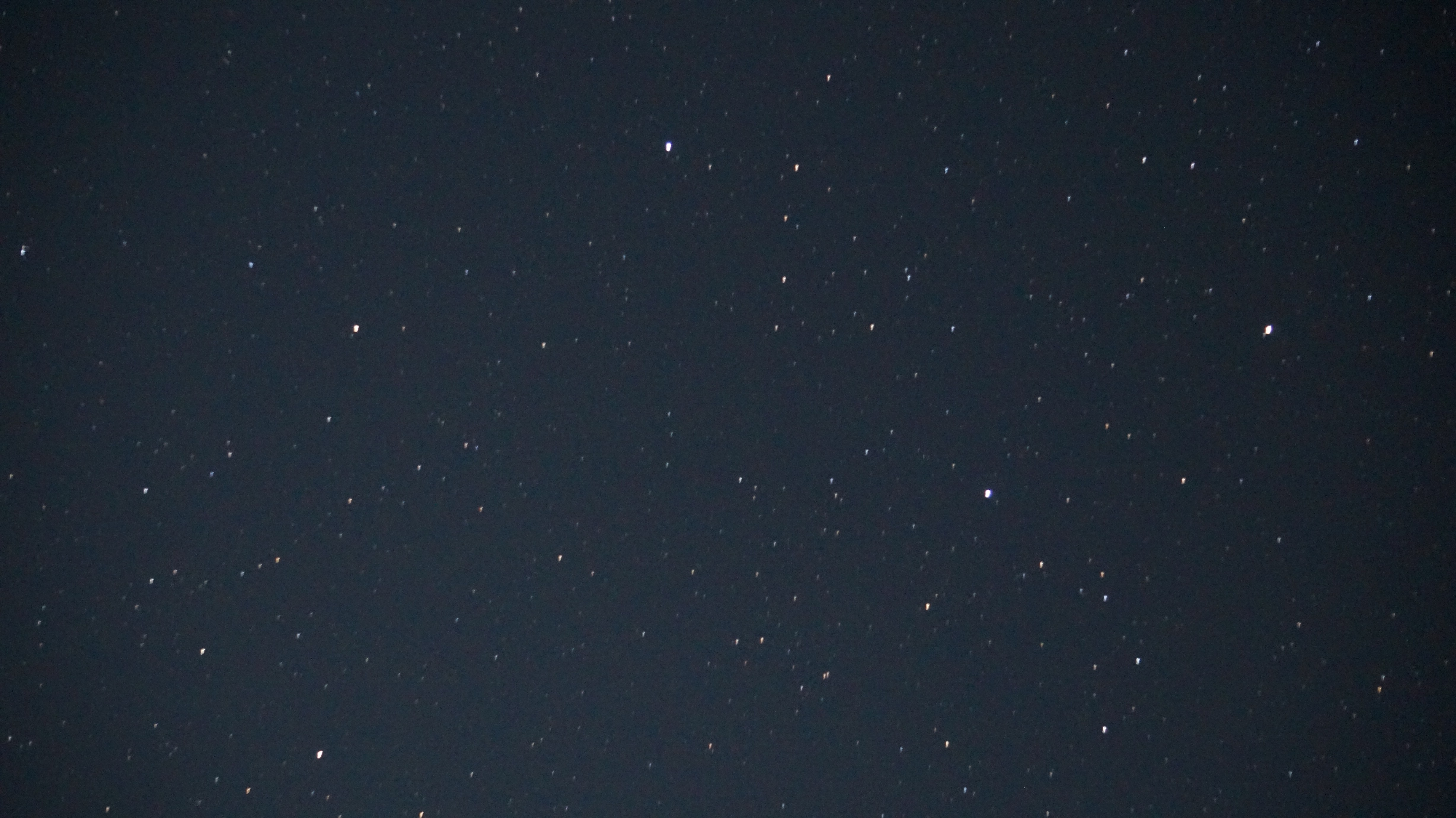
That said, it was very clear that the tracking was helping. The below images show without and with tracking, respectively. While a bit out of focus and with poor balance, the second image is close to the goals of this project, preventing most of the star trails.
![]()
![]()
-
Custom PCB Testing
06/14/2020 at 18:58 • 0 commentsI did initial testing with an Adafruit Adalogger M0 and standard 28BYJ-48 driver. The driver uses the ULN2003 darlington transistor array. I also tested out the ability to trigger the shutter on my Sony Nex-6 camera with an infrared LED. Although this worked, I didn't see the real need for camera control built in. Maybe if I build a future wirelessly controlled version I will add that, but for now it is easy enough to use the delayed shutter mode on the camera itself. Note that for astrophotography you want to ensure a delayed shutter so that pushing of the button doesn't shake the camera too much and ruin the photo. After proving this worked out, I designed a custom PCB for the driving. I decided to try out JLCPCB's assembly service and EasyEDA for this design, since it was so simple. I had previously used Macrofab's prototype assembly service, but they recently changed their focus away from that, vastly increasing their starting price. JLCPCB has a set of parts that they will assemble onto your board for a very low cost and fairly fast turnaround, but with strict limitations:
- All placed parts must be on one side
- Only parts in their library can be placed
- https://jlcpcb.com/parts
- Their search/filtering tools are unbelievably AWFUL, so it is quite difficult and time consuming to search through their parts listings
- They have no connectors supported. Even a standard USB micro would be incredibly useful, but alas. I used a strange vertical through-hole USB micro connector instead that I soldered by hand
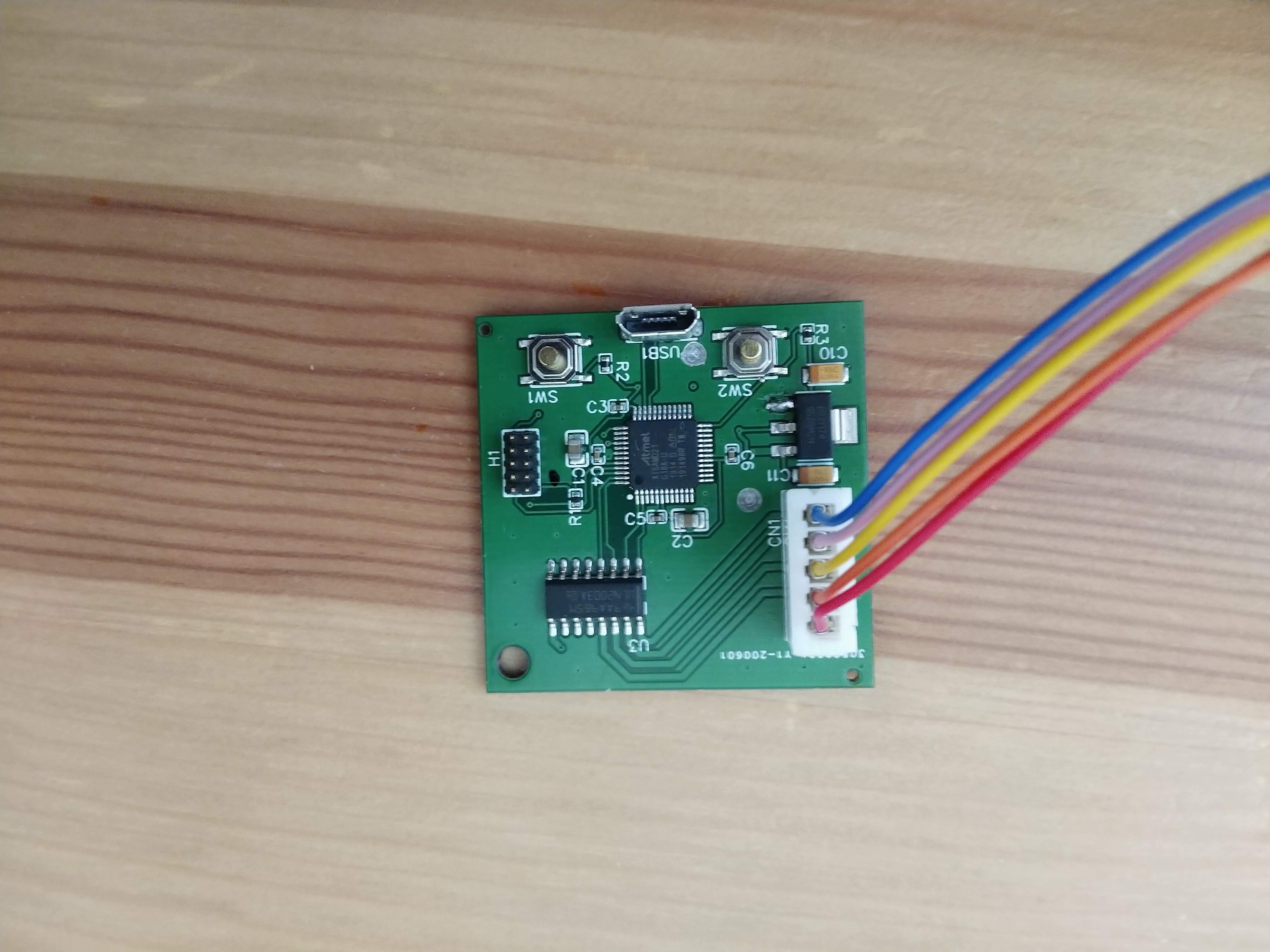
The boards are relatively simple, with a few main parts:
- USB micro for power
- ATSAMD21G18A microcontroller (way overkill, but available on JLCPCB)
- Standard cortex programmer header
- Two pushbuttons for control
- Strange-brand but very cheap LDO 3.3V regulator
- ULN2003A darlington transistor array
- B5B-XH-AM (LF)(SN) connector to stepper motor
The boards seem decent quality. However, I immediately noticed a major problem. Unlike Eagle, EasyEDA doesn't show the top and bottom layers partially transparent. Therefore, when I did some via stitching of the ground planes I accidentally put two vias between GND and the 5V input, shorting them together. Thankfully, I was able to drill them out on both sides to separate them. Note the two drilled spots on the board below.
![]()
The firmware for this system is simple. All we need is the ability to manually step the system in both directions, and the ability to change into a mode with will track a constant rotation rate. The only difficult part is the inverse kinematics to determine how many steps to drive and at what time to do that. I set the problem up as a tracking control problem with a simple proportional controller. The system has no position feedback, so it assumes it is properly set to be fully retracted upon boot. Over time, a desired angle is determined based on a constant rotation rate of 15 deg/s. The current position is calculated, and a certain number of steps are calculated and executed as below:
// Simple P controller
float current_angle_deg = calculate_current_angle_deg();
int32_t steps_to_move = (int32_t) -50.0 * (desired_angle_deg - current_angle_deg); // move out
step_motor(steps_to_move);
The remaining difficult part is to determine the current angle based on the number of steps. The stepper motor has internal gearing so that the number of steps per revolution is 2037.8864, and the M5 threaded rod has a 0.8mm pitch. Therefore, it is easy to calculate the linear motion per step, but that does not tell us angle directly. Due to the 3 hinges, the true equations are fairly complicated. For now, I am approximating it as a triangle and use the law of cosines to determine the current angle. Based on testing, I will see if this is good enough.
All of the firmware is on the Github linked to the project.
Finally, below is a time lapse, slowed by 32X of the system "tracking the stars." There is a bit of wobble due to misalignment of the threaded rod which may become an issue, but I will know better once I get a chance to test it. -
Hardware Design
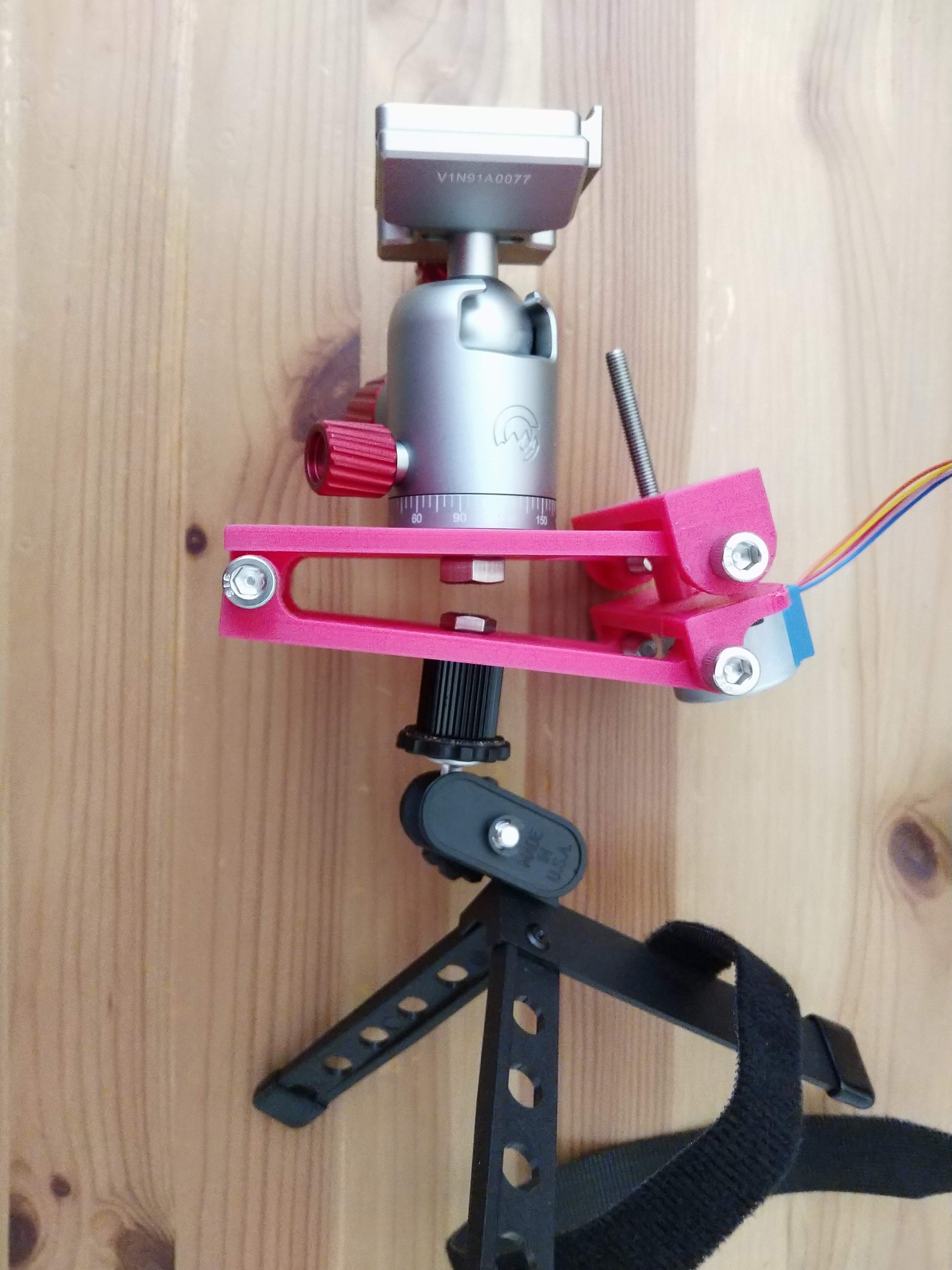
06/14/2020 at 18:28 • 0 commentsThe hardware design is relatively simple. Since it is a single-axis tracker, it only needs one degree-of-actuated-freedom. We also need the ability to orient the system according to the latitude to square up the system to the axis of the Earth's rotation. There are 5 3D printed components in this first design:
- Bottom plate
- Top plate
- Shaft coupler between stepper's D-shaft and the M5 threaded rod
- Motor mount
- Threaded rod nut mount
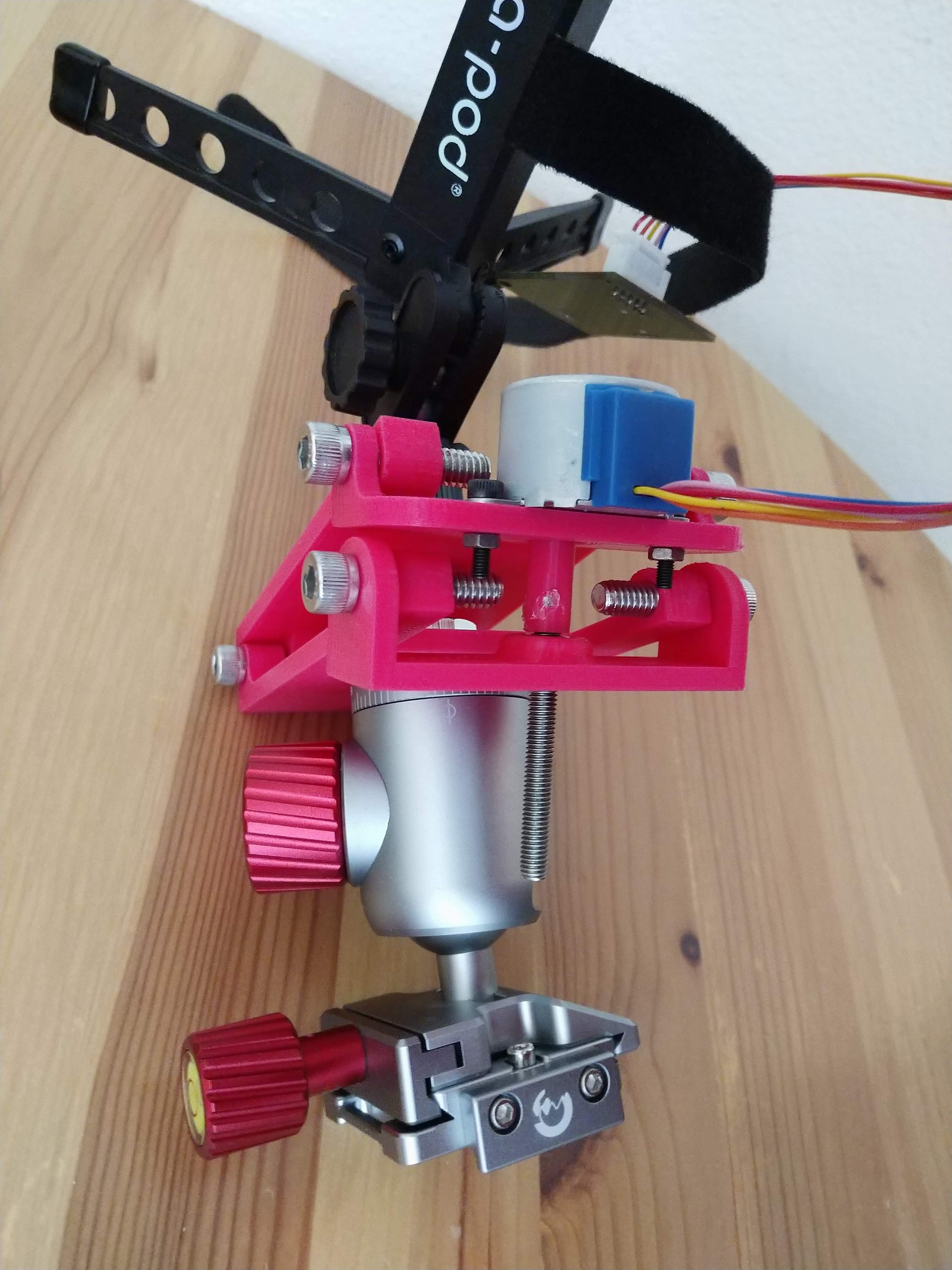
All parts are assembled with 3 unique hinges so that hinge slowly rotates as the stepper motor drives the threaded rod. This prevents back-driving so that no power is required to hold position, and the stepper motor has a huge amount of mechanical advantage. Even the small, relatively low power 28BYJ-48 stepper motor is capable of actuating a large amount of weight. The hinge only needs to move at 15 degrees/hour (360 degrees / 24 hours), so speed is not important. In fact, we want the rotation to be very smooth so as not to disturb the picture. The extra degree of freedom for orienting the hinge to be parallel to the Earth's axis of rotation is assumed to be in the tripod. Note that the tripod shown below is not quite strong enough, so I will need to get larger one. A COTS ball mount is also used on top to allow easy mounting of the camera and to avoid interference with the threaded rod.
![]()
An M5 nut is press fit into one of the 3D printed parts, which is then driven by the threaded rod.
![]()
Astrophotography Star Tracker
Single axis barn-door style star tracker for long exposure astrophotography