 ikhsan ismail
-
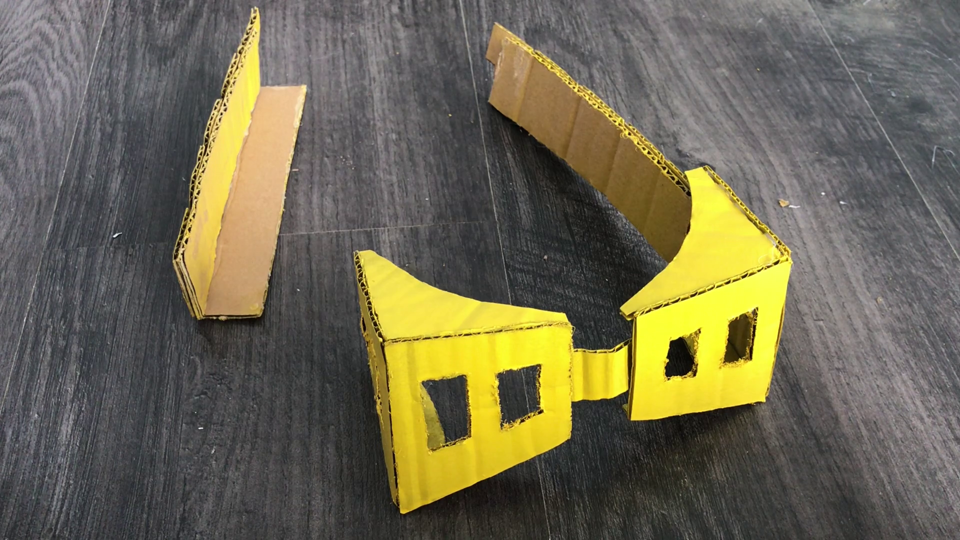
1Making Eraser Head Goggles From Cardboard
- Lay out the cut-outs as shown in the picture
- Assembling with hot glue
- Paint the goggles with a yellow spraycan.
- Let it dray
![]()
![]()
![]()
![]()
-
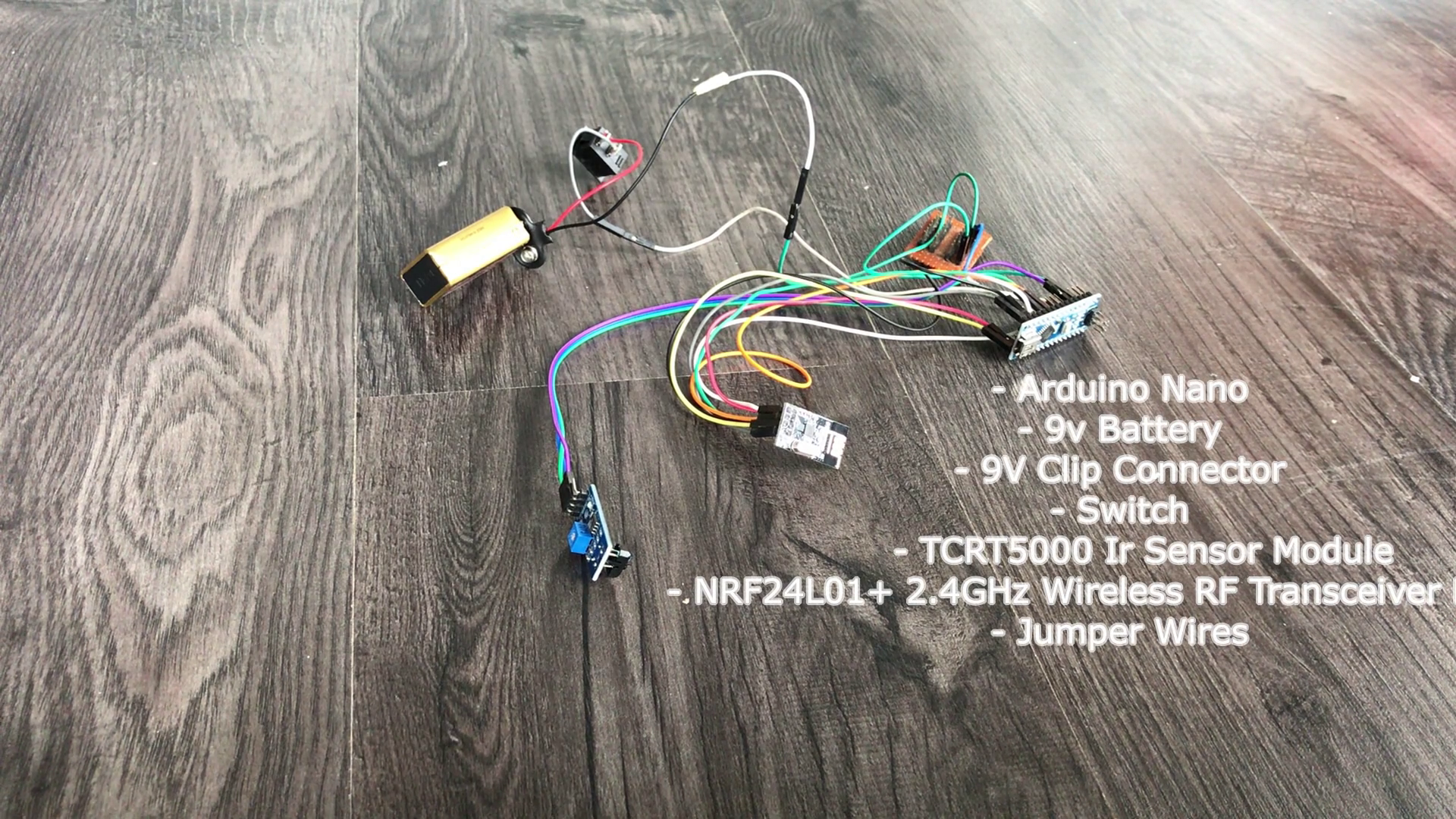
2Wiring Diagram for Transmitter (Eraser Head Goggles)
The following image shows the complete wiring diagram of transmitter using Arduino Nano. After connecting all components then I inserted all these components into the enclosure and sealed it completely using hotglue.
The Ir sensor detects the blink to switch ON the lamp and if the ir sensor detects the blink again the switch will OFF.
NRF24L01 2.4 GHz Transceiver Module can be used for wireless communications at up to 100 meters.T he operating voltage of the module is from 1.9 to 3.6V, but the good thing is that the other pins tolerate 5V logic. The module communicates using SPI protocol. You should make looking at the arduino pin connector model SPI pins.
![]()
-
3Transmitter (Eraser Head Goggles) Code
You need to do is install RF24 Library. You will get an error if you dont install.
When you want to add a new library into your Arduino IDE. Go to the directory where you have downloaded the ZIP file of the library. Extract the ZIP file with all its folder structure in a temporary folder, then select the main folder, that should have the library name. Copy it in the “libraries” folder inside your sketchbook.
Connect the arduino nano and upload the given program on your arduino nano.
-
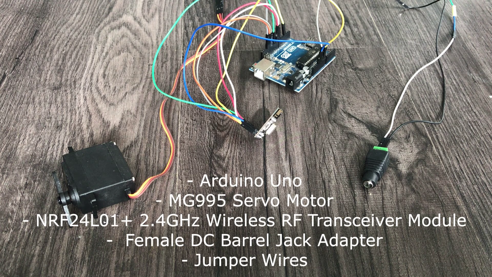
4Wiring Diagram For Receiver
When moving a servo motor with Arduino, as with other motors, it is almost impossible to draw voltage or current from Arduino. In this case, you can take the external power supply and transmit angle control signals only from Arduino to control the servo motor.
For example, Arduino UNO R3, has I/O pins (digital/analog pins) that draw approximately 20mA from each individual pin (with possibility of damage if 40 mA+). Even though the operating voltage of the servo motor is 5V, since the power supply from the digital/analog pin is insufficient in electric current, the servo motor and Arduino can be damaged.
In the case of a MG995 servo motor with an operating voltage of 5-7 V, it’s necessary to supply power to the servo motor separately from Arduino as shown in the circuit diagram below.
![]()
-
5Receiver Code
Connect arduino the PC using USB cable and upload the given program on your arduino uno.
-
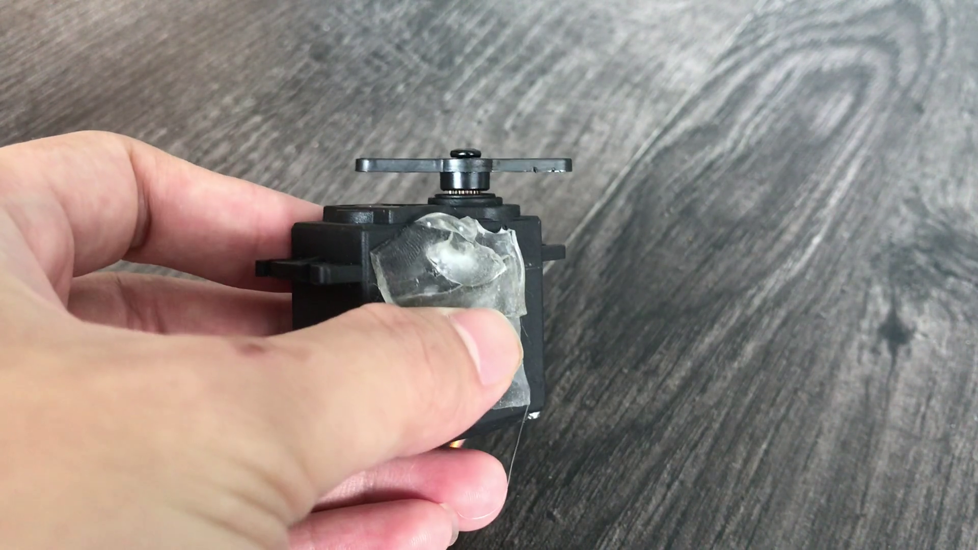
6Setting Up The Servo
![]()
I used a double tape to attach the device to the light switch. When you are done, test to see if the servo motor works correctly and it turns on/off the light
-
7Finish
Does it work? Good! I hope you enjoyed this Arduino project and learned something new. You can subscribe my channel for the support.
Thank You.
Eye Blink Controlled Light Switch
The Goggles paired with sensor detect the motion of an eye, activating a range of hands-free task such as turning on /off a light.


Discussions
Become a Hackaday.io Member
Create an account to leave a comment. Already have an account? Log In.