opentag
-
Choosing an MP3 Player for Arduino
11/15/2021 at 05:24 • 0 commentsI would like to add better sounds to the laser tag game. Right now, I have sounds from a piezo, but I'd like to have more complicated sounds than a single tone from a Piezo. I'm planning on offloading that to a stand alone chip. I've been researching options, and have come up with the following criteria:
- Clear tutorial. I don't want to have to dig through data sheets to find out how to use this thing, as I don't have a lot of time to work on this
- Cheap. I don't want to spend a lot of money.
- Easy to add / change different sound files
- Onboard audio amplifier is a plus. I can add one, but having everything on one chip would be simpler, as I'm not sure how loud it should be.
Here are the options I've found:
DY-SV5W Voice Playback Module

(Picture from AlliExpress)
This has an SD card slot to hold the files (which to me, is preferable to downloading onto a chip), and has instructions on all of the commands here. There is a "cheat sheet" of all of the raw commands here. And, to top it all off, someone has written a library for all the commands, linked here, called DYPlayer for arduino. The DY-SV5W is on the list of tested modules for the library, so it should work.
Purchase link to one on AlliExpress is here. There are probably cheaper ones. that's the one I found during my research. Speakers are here. Other option is here.
I got this one hooked up to the prototype laser tag, using an ATmega4809 (I used up all the serial ports on the ATmega328p), and the examples from the library on Github (again, here) made it super simple to get a sound playing on the speaker. Since this was easy to get set up, I'll probably go with this for adding better sounds to the laser tag game. I'll need to find/make the mp3 files for the different sounds I want, but that will be something for the future. For now, the hardware works.
I looked into other modules, and they are listed here in case I ever want to go back and use them.
Mini MP3 Module
Tutorial showing how to add a sound amplifier is here.
Tutorial does not show how to get sounds on the device.
AlliExpress link is here.
DY-SV17F Module
Tutorial is here.
Tutorial does not show how to get sounds onto the device. It also doesn't show how to change the modes of operation, which are listed in the instructions here. It needs to be set to UART mode, unless you want to control it differently.
AlliExpress link is here.
Another Module
This is the one I purchased: https://www.aliexpress.com/item/32782488336.html?spm=2114.12057483.0.0.26012e93zs9XzW
-
New OLED image code and Library
08/14/2021 at 05:52 • 0 commentsWell, I ran out of RAM and programming space to use Adafruit's OLED library. Bummer. But, not to worry, there are other arduino libraries for graphics. Some of which use very little RAM. Like this one.
This library uses minimal RAM and is a small enough library that I can use it with all the other code I've written. Perfect.
Well, except, the way that I made the images now no longer works. I have to convert all of the images to XBM, a different format from the ones that the adafruit library uses. And I couldn't get the images to be displayed on the bottom row. So they are on the top row now. Oh well. That's not a big deal.
So, to convert the images to XBM, I first had to scale the png images that I had to the correct pixel size. I'm using 26x32 for most of the images (so I can fit Fire, Water, Ice, Poison, and Lightning in 128 pixels. Lightning is a little smaller, so the rest can be 26 pixels wide). Quick Googling found this tool to resize the png to the correct size. I then used Convert.io to convert the file from a png to a XBM. You can then download the file and open it in notepad to see the bits (in hex). Copy that to arduino and store it into program memory, and we are good to go with new images. The water drop icon is shown below:
{
0x00, 0x00, 0x00, 0x00, 0x00, 0x00, 0x00, 0x00, 0x00, 0x30, 0x00, 0x00, 0x00, 0x30, 0x00, 0x00, 0x00, 0x78, 0x00, 0x00, 0x00, 0x78, 0x00, 0x00, 0x00, 0xFC, 0x00, 0x00, 0x00, 0xFC, 0x00, 0x00, 0x00, 0xFE, 0x01, 0x00, 0x00, 0xFE, 0x01, 0x00, 0x00, 0xFF, 0x03, 0x00, 0x00, 0xFF, 0x03, 0x00, 0x80, 0xFF, 0x07, 0x00, 0x80, 0xFF, 0x07, 0x00, 0xC0, 0xFF, 0x0F, 0x00, 0xC0, 0xFF, 0x0F, 0x00, 0xC0, 0xFF, 0x1F, 0x00, 0xE0, 0xFF, 0x1F, 0x00, 0xE0, 0xFF, 0x1F, 0x00, 0xE0, 0xFF, 0x1F, 0x00, 0xE0, 0xFF, 0x1F, 0x00, 0xF0, 0xFF, 0x3F, 0x00, 0x30, 0xFF, 0x3F, 0x00, 0x20, 0xFF, 0x1F, 0x00, 0x60, 0xFF, 0x1F, 0x00, 0x60, 0xFE, 0x1F, 0x00, 0xE0, 0xFC, 0x1F, 0x00, 0xC0, 0xF0, 0x0F, 0x00, 0x80, 0xE3, 0x07, 0x00, 0x80, 0xFF, 0x07, 0x00, 0x00, 0xFE, 0x01, 0x00, 0x00, 0x78, 0x00, 0x00, };
Isn't it beautiful ;) ?
-
Testing Different IR Receiver Placement
07/27/2021 at 05:26 • 0 commentsI tested out three different versions of IR receiver placement on your head. I'm sticking with placing these on top of the head for now instead of on the device, since you can get consistent 360 degree coverage on someone's head. When playing with friends, people tried to hide their device to not get tagged, thinking that would save them. So, instead of trusting that humans will change (and not try to cheat), I'm designing the system around them.
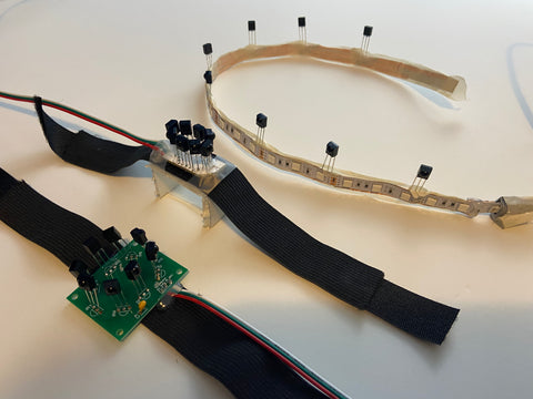
From bottom left to top right in the picture below, there is the first version, with eight IR receivers in an octagon shape (to give 360 degree coverage), which sits on top of your head. When testing with this one, it was hard to consistently tag people, as they would tilt their head up (changing the angle, so you couldn't hit the IR receivers, as their forehead would block the beam), or their hair would get in the way.
The second version, the one in the middle, has a tighter pattern of IR receivers (still covering the 360 degree angles, just more compact), and it is sitting on top of a one inch tall stand to make it sit an inch up from the top of your head. This one was easier to hit, despite people's hair or head tilt.
In the third version, top right, I soldered the infrared receivers onto copper tape along the RGB LED strip. That way, there was an IR receiver on the person's forehead (making it very easy to see and hit).
A closer image of the IR receivers soldered to copper tape I placed on the back of the RGB LED strip is shown below.
After comparing these three setups for IR receivers, I found that the second one was more reliable. For some reason, the IR receivers attached to the RGB LED strip performed the worst. I would have thought it would do better, but when tagging it, the device consistently missed consecutive tags (fired within 1/3rd of a second. Slower than that, and it got all of them). I don't know if there is some capacitance in the copper tape or something that the device is picking up, but from the experiment, I should do the next series of tests with the second version. Hopefully, it will give me the reliability and ease of tagging that I'm looking for.
-
Headband Improvement and new PCB
07/10/2021 at 01:25 • 0 commentsGot a new white PCB and soldered it up. Looks pretty good, if I do say so myself.
I also made some changes to the headband to use elastic strips instead of only using velcro (hook and loop) strips. I used hot glue to attach the velcro to the elastic, and it works fine. The only thing that sometimes gets in the way is hair, so the headband is more reliable when you put it on over a hat (baseball hats seem to work pretty well for this).
For the next series of tests, I'm going to try adding the IR receivers onto the RGB LED strip, and compare that to raising the IR receivers one inch up off of the top of the player's head. There were a few occasions where I couldn't seem to tag someone, and it may be because the IR receivers were blocked by the other player's head. But, overall, the devices work and you can play a game of laser tag with them. Woohoo!
Also made some minor code changes to make it easier to see when you've hit someone with a status effect (poison, fire, etc.). Their headband now stays that color while they have that effect active (red for fire, green for poison, etc.). This will make it easier for players to work together and combine their abilities.
-
Case Improvements
05/12/2021 at 04:06 • 0 commentsBuilt a couple devices, played, and overall, it works! One issue that came up was difficulty aiming. The IR LED and the lens were not aligned very well on some of the devices, and that got me thinking. I want the IR LED to be held firmly in the proper direction, and I want to do the same thing for the lens. In addition to that, if I can't get them to be precisely aligned, I can have the sights be adjustable. So, if the device actually sends tags a little to the left, you can adjust the sights a little to the left, and the device will be much easier to aim.
With the goal of making it easy to tag other people, I re-designed the front sight and the LED holder, as shown below.
The IR LED is now clamped in place by the acrylic case. To do this, I cut a slot in the acrylic and undersized the hole that the LED slots into. This displaces the acrylic and turns it into a kind of spring to keep the IR LED aligned. The IR LED can then be soldered onto the board while held in the proper orientation.
For the front sight, it now has a slot in it and is secured by a screw, so it can adjust up, down, left or right to align with wherever the device is actually aiming at. While this might not be necessary with the improvements in holding the IR LED in the proper position, the lens can still be knocked around and may not be perfectly aligned. Even when doing my best to keep it straight, the device did tend to send tags slightly to the left (due to the lens being slightly tilted to the left, even after trying to get it to stay straight). With a little adjustment of the sight, I was able to consistently aim at and tag a target.
-
Building a Case and new PCB version
04/12/2021 at 04:49 • 0 commentsDuring the pandemic, I've had a bit of time to build laser tag. The last few weeks, I've been working on a case, new PCB's, and adding a lens to increase the range that the devices can send tags. At night, from a test just a moment ago, the normal range tags go over 200 feet, and the short range tags go about thirty feet. That's around where I want them to be. It's probably a bit shorter during the day, but I haven't done the daytime testing yet.
This is quite a bit of an improvement over the prototype, shown below. I mean, they both work, but one of them is definitely a lot cleaner looking. And held together with more than tape and love.
Also, the screen, indicator LED's, and sights all seem to be working well. The indicator LED's are a pretty big improvement in my book, considering that some players gave me feedback that it was hard to tell whether or not they were actually tagging other players. Indicator LED's solve that. If you successfully tag a player, your green "Good Hit" LED will blink. If you hit them with an ability, but it hit their armor (and therefore, the ability was blocked), the yellow "Hit Armor" LED will blink. If you are tagged, the red "Hit You" LED will blink, and an on board vibration motor will vibrate to indicate that you have been tagged.
I have a couple more minor tweaks to the case and PCB that I want to make, but the system as a whole is working nicely. I think I've gotten it to a place where it meets the requirements for version 1.0. I'll make a few of them to test that the functionality is what I want, but if it's there, then this is ready to be promoted to version 1.0! (Which, for me, means that it's at a place where it has all of the core functionality that I want it to have. And, it's a revision or two from being there)
-
How to Program Class Selection
03/01/2021 at 05:30 • 0 commentsThis entry is going to be a little coding specific, but I think it may be helpful to someone to understand how I went about adding features to the code, in case people want to do something similar in the future. You can follow a similar process.
The first thing that I needed to do was figure out what I wanted the code to do. I wanted to allow a player to change their class for a short period of time after they are revived. They shouldn't be able to change classes in the middle of the game, because every time you change class, your health is reset. It would be pretty unfair to get hit a few times, then change classes to get full health in the middle of the game.
After you are revived (or when you power up the device), you should have a short amount of time, say, 5 seconds, where you can change your class (1). During this time, players can press the "change class button" to change classes (2). You need to know what your class is every time you change it, so the OLED should display your class every time you change it (3). At the end of that time, the OLED should switch to showing your current health (4). When that happens, your class is set, and you can't change it anymore. Understanding and writing this out was the most important part of changing the code. Without an understanding of how I want the code to work, it would be nearly impossible to make the change and make everything work.
So, knowing what I want the code to do, I now have to make changes to the code.
- To keep track of when you can change your classes, I created a new variable. When you are revived (or start the game, which uses the same function), that function sets this variable to 5 seconds in the future. As long as the current time hasn't passed this stored time, you can change classes. Show your current class and team on the OLED (using an OLED controlling function, which I'd already written)
- I added a button (active low), and used some logic I use for other buttons to only change classes once when the button is pressed. (I check if the button's state changed from not pressed to pressed. If so, change class to another valid class).
- When the class changes, update the OLED.
- Once I've passed the time where I can no longer change classes, change the OLED to show current health
After going of that, I went into the code and added a function that did those things. I had to change some of the original code, as the function that I had that changed classes had other stuff bundled in it. So I pulled those things out so that I could call on them in this new function. I know this is a little hand-wavy about how I actually implemented the change, but I don't think going over the line by line changes is as helpful as going over the high level thinking that went into the change. If you really want to know how I did that, I'd be happy to send you the two versions for you to do a code comparison. The diagram of the functional blocks of code is shown below.
-
Team and Class Selection Design
02/17/2021 at 06:36 • 0 commentsI'm thinking through a re-design of how players can select their team and class. While I do have a base that players can use to change their class and team, I'd like players to be able to utilize as much of the game as possible without needing a base. And so that's the main requirement.
In addition to that requirement, there is a constraint. Players should not be able to change their class while they have health, or in the first few seconds of starting up their device. This is primarily going to be controlled by the software, so that shouldn't be too difficult for any of the solutions below.
From there, I have a couple of objectives that I'd like the design to optimize:
- Ease of use - it should be easy to change classes
- Ease of expansion - There should be the ability to expand classes (and teams) in the future without a hardware change
- Cost - shouldn't add too much extra hardware (relative to the other options, none of this hardware is actually very expensive)
Here are the options (at least, the ones I could think of for now) for how to let a user select their team and class, and how I rate them on how well they meet these objectives:
Option Ease of Use Ease of Expansion Cost Potentiometer High Low Medium Menu with button select Medium High Low Menu with Rotary Encoder Medium High High Voltage Divider Low High Low Menu with Shift Register High High High And now for a little explanation of each:
Potentiometer
I'm currently using a potentiometer with labels around it on the circuit board. Just point the potentiometer to the class you want to play, and when you reset your device, you start the game as that class and team. Because the labels are on the board, it's not easy for someone to add classes or teams to the game and have those classes or teams be selectable with the potentiometer.
Menu with Button Select
This would be similar to how a digital wrist watch works. On startup, you can push a button to change your class, or another to change your team. You have a few seconds to do so. This means that every time you reset your device, you will have to select your team and class again, as it doesn't save. Not having the selection carry over is a little more annoying than the potentiometer, but that may be fine.
This could also let players select the number of lives that they start with, which could be a fun addition to the game.
Rotary Encoder
Similar to the potentiometer, I can use a rotary encoder to allow users to select their team and class. This would also require a menu on the screen, since the rotary encoder can continuously rotate, so you'd have to have the encoder scroll through items on a screen, similarly to how the menu with button select would work. It's more expensive and takes more pins than buttons, and provides the same functionality as buttons. But it is cool.
Voltage Divider
Let people plug different resistors into the board and have the arduino read the voltage. This requires that players swap out resistors on their board whenever they want to change teams or classes. This can cause quite a headache to look up the resistor values you want, find the resistors, plug them in, realize you lost the ones you need, etc.
It's very expandable, but it isn't very easy for the user.
Shift Register
I can add more inputs and have someone select their class and/or team using a shift register, which is detailed here. Then I could add a button for each class and a button for each team. But, then again, you'd need space for new classes and teams that are introduced later, or this would just let you have a keypad or lots of buttons to control a menu screen where you can change your class and/or team at the same time. It would be cool, but it doesn't seem worth it when there are simpler options that do the same thing.
Conclusion
Voltage divider isn't easy to use, so that's out. Shift register, rotary encoder and buttons all need a menu, and the buttons are the simplest of that group. So that leaves controlling your class and team with buttons and a menu on the OLED screen or with a potentiometer. The trade off is ease of use vs the ability to add more classes and teams in the future. It's easier to tell someone to turn a knob to point at the team you want to play, but you can't add new teams easily (since the teams are printed on the circuit board, and you'd need to put new labels on the board to get new teams). With a button, you can easily push it to change teams or your class, but you have to do it every time you restart. If you are playing with teams, you don't want to have to reset your team and your class every time. So, why not both?
The number of teams is most likely not going to change in the future. People can add more teams, but you would need to modify the tag protocol to do so, which would require a lot of knowledge of the system and how it works. Plus, I don't like the idea of having to change your team every time you reset your device.
The number of classes is probably going to change in the future. For that reason, using a method that allows you to expand what you can select is a good thing. Hence, using a button that changes your class and displays it on the OLED at startup.
The downside of having your class be determined with a button while your team is determined by a potentiometer is that the player now has to learn more information to play the game. Instead of learning one system, they have to learn two. The trade-off here is, once again, how easy it is to pick up and play the game versus how easy it is to expand upon. I think in this case, I'm going to go with how easy it is to expand upon. At the start of each game, players can select their class with a button and their team with a potentiometer. I think that strikes a good balance between my objectives.
-
New case and PCB Design - Prototypes
01/18/2021 at 05:34 • 0 commentsI've been upgrading the case and PCB design into a new form factor, one that looks much more like a gun. Compared to the first prototypes, this has a number of advantages:
- Easier to aim
- Easier to see the OLED screen while aiming
- Has indicator LED's to indicate if you have tagged someone or have been tagged yourself, and these indicator LED's are also easy to see
- Uses three AA's instead of six, using a boost converter
- Easier to hold with one hand
I made a quick prototype on a perforated breadboard, and it's starting to come together:
Also, I've been adding more hardware since the last PCB's that I've made, like the OLED, indicator LED's, and the HC-12 wireless transceivers. So, I added the new hardware, changed the size to fit in the new case and uploaded the files to OSH park.
$104 for three boards!
I'm used to these being $20 to $50 depending on how big they are. So I tried PCBWay. $95 for 5 boards. If I was making a couple hundred, then the price per board would be lower, but that was more than I wanted to spend on the prototype. So, I redesigned the board a little bit so that it was a bit smaller. It came in at a more manageable $60 at OSH park. Plus, when I have more time, I can panelize it to make the boards more cost efficient, as there are now three boards per device. But, I'll do that later after I've tested the thing and determined if the design actually works. I ended up getting them a Seeed Studio, as they had the cheapest boards for these dimensions.
-
Time Multiplexing with the HC-12 Wireless Transceiver Module
12/07/2020 at 01:00 • 0 commentsI'm using the HC-12 wireless transceiver module to allow each laser tag device to communicate wirelessly. The idea is that when you are tagged by someone, you can communicate back to the device that tagged you. That way, when you tag someone, you can indicate on your device that you successfully tagged someone. I got some feedback from players that it was hard to tell if they were tagging other people. The LED's on your head blink when you tag someone, but adding an indicator on your device may help. Plus, it paves the way to adding all sorts of other features that I want to have in the future, like regaining health when you tag someone.
I chose the HC-12 instead of the nRF24L01+ for a few reasons:
- I am using just about every single pin on the arduino UNO, and I don't have enough pins to support the nRF24L01+, and I have enough pins for the HC-12
- I am using 90% of the program memory on the arduino UNO, and I don't want to add another library and potentially run out of program space for other features I want to add later
And yes, I could upgrade to a different microcontroller and get more pins, more program memory, etc. And, for the next version, I'm planning on using a Blue Pill, if it meets the requirements for version 2.0. But, if I want to release a completed version 1.0, then I need to stop giving in to feature creep. Plus, based on my experience, the arduino UNO is a much easier starting point for beginners. Getting the Blue Pill running was a minor headache, as the tutorials I followed did not spell out how to do everything, and I had to do a bit of Googling and talk to a friend who had used one before in order for me to get it running using the Arduino software. The ultimate goal for this project is to make this beginner friendly, so if I can use an UNO, which has a low barrier to entry, then I'm going to.
After getting the radio set up (with the help of this tutorial) and reading the data sheet, I decided to have each device set to a different frequency. That way, I wouldn't have to worry about devices trying to send data at the same time, which would cause the radios to collide and potentially not send the correct data. And, then, after implementing it, I realized that it takes 40 ms to enter programming mode, and 80 ms to leave it. If you get tagged, change channels, send a message, and then change channels back, that's 240 ms, or about a quarter of a second. Which means that mostly, you aren't going to be listening for whether or not you have tagged someone else. And, if you are tagged by two or more people (which, can happen every 350 ms), you won't have enough time to switch back and forth between the two radio channels to send the data to each person. In essence, with at 240 ms delay between sending each data packet, this system can't scale with multiple people sending and receiving tags at the same time.
To fix this, I decided to use time multiplexing to keep the devices from sending radio transmissions at the same time. The way I set this up is as follows:
- A base, or "master" device, sends a command to enter time sync mode. In this mode, the arduino ignores everything except for sending and receiving radio commands
- The base, or "master" device, sends a command to synchronize all radios.
- Once synchronized (or, if it times out), each device picks a set time from the synchronize radio command to send any data that it needs to send.
For example, if there are three radios, and I want them to send data one time a second, then the first radio will send the data in the first third of a second, the second radio will send data in the second third of a second, and then the third radio will send data in the last third of a second. Every second, all three radios can send data, and they will always send in the order, 1,2,3 (if they have any data to send). I've set up the system to send data every 250 ms, with a 3 ms window for each device to send, and 2 ms of silence (for 25 total transmitting devices). That way (hopefully), during a 5-15 minute game of laser tag, none of the devices send data at the same time, even if they drift a bit from the correct time to send (each clock has up to 5% error with the resonators I'm using).
So far, when testing on the bench, the system works. I've ran into some weird quirks, where it takes about 40 seconds before I can tag multiple devices at the same time and have them both send data properly, or that when I have a device constantly outputting radio chatter, the devices can't communicate (there is a limit on the amount of radio chatter that can happen before the system breaks down), but, so far, it's working. Mostly. I'll have to check it in the field to see how well it works with 8-10 players, and five bases, but so far it looks promising.
I may need to play with the baud rates to get it to work reliably, but so far, so good.
I'll definitely upgrade this to using the nRF24L01+ and using their Multiceiver (TM) functionality, but so far, everything is working alright.
If you want to check out the code or use it in your own project, I've included the two functions for sending and receiving code below.
If you want to check it out in the context of the full laser tag code, you can find that through the link below. The functions used are:
- wireless_transceiver( int device_id, int message, int value) - used to send radio transmissions at a set time
- receive_wireless(void) - used to receive radio transmissions
- telegraph_tags(int check_variable) - used to blink an LED for a set time if you've tagged someone
Note that I try to avoid using delays in my code. To avoid this, I call each of these functions in the main loop and use the milis() function to check whether or not it's time to send radio data or turn off an LED.
https://create.arduino.cc/editor/gukropina1/4b1b9bc5-1348-4545-bb0a-6da691361e60/preview
But anyway, here's the code. If you want to check out more about the project, click here.
#define RADIO_TIME_PER_DEVICE 3             //each device has a 3 ms window to transmit
#define RADIO_SILENCE_TIME 2                //each device has 2 ms of silence between transmit times
#define WIRELESS_SEND_BUFFER 24             //can store 24 bytes (8 messages) for sending out the radio
#define WIRELESS_MESSAGE_LENGTH 3           //number of bytes in radio messages
#define SET_PIN 4                           //programming pin for radios
#define MAX_RADIOS_USED 25                  //maximum number of radios used
//time in microseconds for all radios to send their instructions, before they loop and can send again
//RADIO_PERIOD = MAX_RADIOS_USED*(RADIO_TIME_PER_DEVICE + RADIO_SILENCE_TIME);
#define RADIO_PERIOD 250
//radio bytes:
//first byte: who the transmission is sent to
//second byte: what command is sent
//third byte: value - what value to set things to

#define DEVICE_ID 0

#include <softwareserial.h>

SoftwareSerial HC12(10, 11); // HC-12 TX Pin, HC-12 RX Pin

void setup() {
  pinMode(SET_PIN, OUTPUT);       //set set pin to output
  Serial.begin(9600);             // Serial port to computer
  HC12.begin(9600);               // Serial port to HC12
  digitalWrite(SET_PIN, LOW);     //start programming
  delay(50);                      //delay for HC-12 to go into programming mode
  HC12.print(F("AT+DEFAULT"));    //set HC-12 to default mode
  delay(50);
  digitalWrite(SET_PIN, HIGH);     //end programming
  delay(100);
  while (HC12.available()) {       // The HC-12 has response data (the AT Command response)
      Serial.write(HC12.read());   // Send the data to Serial monitor
    }
  wireless_transceiver(0, -2, 0);  //set the time for sending radio commands
  delay(100);
}

void loop() {

  //check if you need to send wireless information
  wireless_transceiver(0, -1, 0);

  //check if you are sent wireless information
  receive_wireless();

  //check if you need to stop blinking the LED
  telegraph_tags(0);
}


/*******
wireless_transceiver f(x)
This function sends wireless messages and receives wireless messages
Messages are sent / received through the Serial port and the HC-12 transceiver
the send part of the function checks if it is time to send a packet, then sends it.
If it receives a packet to send, it stores it in a buffer
If it is time to send packets, it also checks for any received, and sends them to be processed
message -1 is used to loop this function and check if it's time to send
message -2 is used to set the time that is looped from.
 */

 void wireless_transceiver( int device_id, int message, int value){
  static unsigned long next_event_time;              //time to send next piece of data
  static byte current_status;                        //current step we are on
  static byte array_to_send[WIRELESS_SEND_BUFFER];   //aray to send
  static byte array_index;                           //current array index
  unsigned long current_time = millis();

  //If you get a new message to send, add that to the buffer
  if(message != -1){
    //if message is -1, we are checking if we can send
    if(message == -2){
      //if the message is to set the time for transmissions.
      next_event_time = current_time + (DEVICE_ID*(RADIO_TIME_PER_DEVICE + RADIO_SILENCE_TIME));
    }
    else if(array_index <= WIRELESS_SEND_BUFFER){
      //if we aren't setting the time, and there is room in the array
      array_to_send[array_index] = device_id;       //set array to send
      array_to_send[array_index + 1] = message;
      array_to_send[array_index + 2] = value;
      array_index = array_index + WIRELESS_MESSAGE_LENGTH;
    }
  }

  //check to see if it is time to send
  if(current_time >= next_event_time){
    if(current_time <= (next_event_time + RADIO_TIME_PER_DEVICE)){
      //if we are within the time to send and have data to send, send our data
      if(array_index > 0){
        HC12.write(array_to_send, array_index);  //send all bytes
         //reset array_index to indicate all data is sent
         array_index = 0;
      }

    }
    //update time to send next
    next_event_time = next_event_time + RADIO_PERIOD;
  }
 }

/******
receive_wireless f(x)
Checks to see if there was a wireless message sent to the device over Serial.
If it's an AT command, it is ignored.
Otherwise, checks to see if it's 3 bytes, and is for this device
inputs - nothing
 */
 void receive_wireless (void) {

  static byte message_array[3];
  static byte message_array_index;

  /*
  byte message_array[3];       //note: if you do this, you occasionally miss stuff
  byte message_array_index = 0;
  */
  while (HC12.available()) {        // while data is available
    message_array[message_array_index] = HC12.read();
    Serial.print("Received: ");
    Serial.println(message_array[message_array_index]);
    message_array_index = message_array_index + 1;
    if(message_array_index == 3){
      Serial.println("Received 3 bytes");
      //check to see if you should use what was transmitted
      if(message_array[1] >= 5 && message_array[1] <= 29){
        //if the messages that were sent were global messages, react to them
        if(message_array[1] == 5){
          //received a hello!
          Serial.print("Received hello from: ");
          Serial.println(message_array[2]);
        }
        if(message_array[1] == 6){
          //if the message is to set the time for transmissions, set that in transmissions f(x)
          //wireless_transceiver( 0, -2, 0)
          Serial.print("Received synchronize time!!!!");
          Serial.println(message_array[2]);
          wireless_transceiver(0, -2, 0);  //set the time for sending radio commands
        }
        if(message_array[1] == 10){
          //clear any old bits, which happens at the end of the cycle.
        }
      }
      else if (message_array[0] == DEVICE_ID){
        //if the message is sent to you, parse it and do what it instructs
        switch (message_array[1]){
          case 1:
            //I tagged someone, and should indicate it
            Serial.println("Tagged Someone!!!!");
            telegraph_tags(1);
            break;
          case 2:
            //I tagged someone who had armor, and should indicate it
            Serial.println("Tagged Someone's armor!!");
            telegraph_tags(2);
            break;
          case 3:
            //I tagged someone, and they are out. Do something because of it
            break;
          case 4:
            //I tagged the juggernaut, and they are out because of it. Do something because of it
            Serial.println("I'm the juggernaut now!");
            break;
          default:
            break;
        }
      }
      //reset the array after reading the message
      message_array_index = 0;
    }
  }
 }
/**********
telegraph_tags f(x)
this function shows whether or not the tags you have sent hit someone
this function takes in what light to turn on (1 or 2), along with whether or not
you are checking the lights (0). It then outputs signals to the LED's, whether it was
a good hit (green) or hit armor (yellow)
inputs - integer - 0, 1, or 2
outputs - void - turns on lights on device
#define HIT_ENEMY_DEVICE_PIN A3
#define HIT_ENEMY_ARMOR_PIN A4
 */
void telegraph_tags(int check_variable){
  static unsigned long hit_on_time;
  static unsigned long armor_hit_on_time;
  static byte hit_on;
  static byte armor_on;
  unsigned long current_time = millis();

  switch(check_variable){
    case 0:
      //I'm checkint to see if I need to do anything
      if(hit_on > 0){
        //if I've  hit, check to see if I need to turn off
        if(current_time > hit_on_time){
          //turn off
          digitalWrite(HIT_ENEMY_DEVICE_PIN, LOW);
          hit_on = 0;
        }
      }
      if(armor_on > 0){
        //if I've hit armor, check to see if I need to turn off
        if(current_time > armor_hit_on_time){
          //turn off
          digitalWrite(HIT_ENEMY_ARMOR_PIN, LOW);
          armor_on = 0;
        }
      }
      break;
    case 1:
      //I should turn on green light
      digitalWrite(HIT_ENEMY_DEVICE_PIN, HIGH);
      hit_on_time = current_time + TELEGRAPH_ENEMY_HIT;
      hit_on = 1;
      break;
    case 2:
      //I should turn on yellow light
      digitalWrite(HIT_ENEMY_ARMOR_PIN, HIGH);
      armor_hit_on_time = current_time + TELEGRAPH_ENEMY_HIT;
      armor_on = 1;
      break;
    default:
      //not sure what to do
      break;
  }
}
Open Tag
The best game of laser tag you've never played. Choose your class - from a sniper to a pyro, and customize your own game of laser tag!