opentag
-
PCB Version 0.89
07/29/2020 at 04:56 • 0 commentsGot in the PCB's for the arduino shield from Osh Park.
![arduino shield]()
Now that I have the sensor package for the headband and the arduino shield, it was time to test out these PCB's and see how they are.
First, I checked the PCB with a voltmeter, then soldered on the components, making sure to keep the IR receivers for the headband long (so it's easy to detect on your head) and the IR LED legs long (so it can fit into a case, which is currently being re-designed).
![soldered boards]()
Next, I built another headband and added the sensor package to the headband.
![headband]()
Finally connecting the two together, and voila!
![Version 0.89]()
And, it works! I'm glad that the prototype worked on the first try. Things brings me one step closer to finishing the PCB version of laser tag. I'll need to do at least one more revision of the board before releasing it as version 1.0, but it's definitely getting there. Maybe one or two more revisions, and it'll be good to go!
I learned some things from these boards. First was that there was one inconsistency with the RGB LED wire labeling, and I want to add some sort of connector so that it is easy to plug and unplug the headset from the arduino. It'll make it easier to store.
Check out the kit and more progress on my website: https://open-tag-systems.com/
-
Headband PCB - Version 0.89
07/23/2020 at 02:58 • 0 commentsI sent out the Headband Sensor Package Version 0.89 PCB's to OSH Park, Got three purple PCB's back, and they look great!
![osh park]()
The top and bottom of the boards look pretty good. I could have flipped the resistor silkscreen (the R1, R2 and R3), along with the infrared receiver text so it all aligned, and the capacitor soldering pads may be a bit farther apart than I want, but all in all, it's a good first board. And, it's the first thing I did in upverter. I'll solder one up once I get the arduino shield PCB's in, and then I'll have the soldered version 0.89! (If you're wondering, there was already a soldered version, 0.42, but that one had some issues. It was made in Fritzing, and it was easier to make the boards again in upverter than try to fix the boards in Fritzing).
It's really easy to see the traces on the board. You can see how things are connected without trying too hard, which is pretty cool.
Here's the top:
![top]()
And here's the bottom
![bottom]()
-
Arduino Compatible that plays Laser Tag
07/20/2020 at 14:36 • 0 commentsSo, it's not a far stretch to take an arduino shield and turn it into a full on arduino. Really, an arduino is a development board for the ATmega328p. It has a USB to Serial converter (which I didn't put on my board), a power regulator, a crystal oscillator, a reset button, a power plug, and, of course, the ATmega328p microprocessor.
So, I added those to my board, and presto! You no longer need to add an arduino. It's there.
![]()
This does come with some trade offs. The first is that the board I made does not have a USB to Serial converter. This means you can't plug it into USB on your computer to program it. You will either need an FTDI converter (they sell them on Adafruit, Sparkfun, etc.) or, you will need an actual arduino to (see this tutorial on how to use an arduino board to program the ATmega328p chip).
Second, I used a different power regulator. This one can output twice as much current as the arduino one. So, it should have an easier time providing power to all the components.
Third, I used a resonator instead of a crystal oscillator. Resonators can have less accuracy than crystal oscillators, so the timing of my arduino may not be exactly 16 MHz.
But, it works! I've sent some boards out to Seeed Studio to get manufactured. They are a Chinese PCB fabrication company. The headband and arduino shield were sent to OSH Park. Seed Studio was cheaper for the boards that I'm making, but OSH Park makes nicer boards (OSH Park, by default, uses a higher quality process that I didn't pay for at Seeed Studio. I could have, to compare, but I didn't want to pay more).
Once I get the boards in, we'll see if everything works. The design is in Upverter, and can be found here.
-
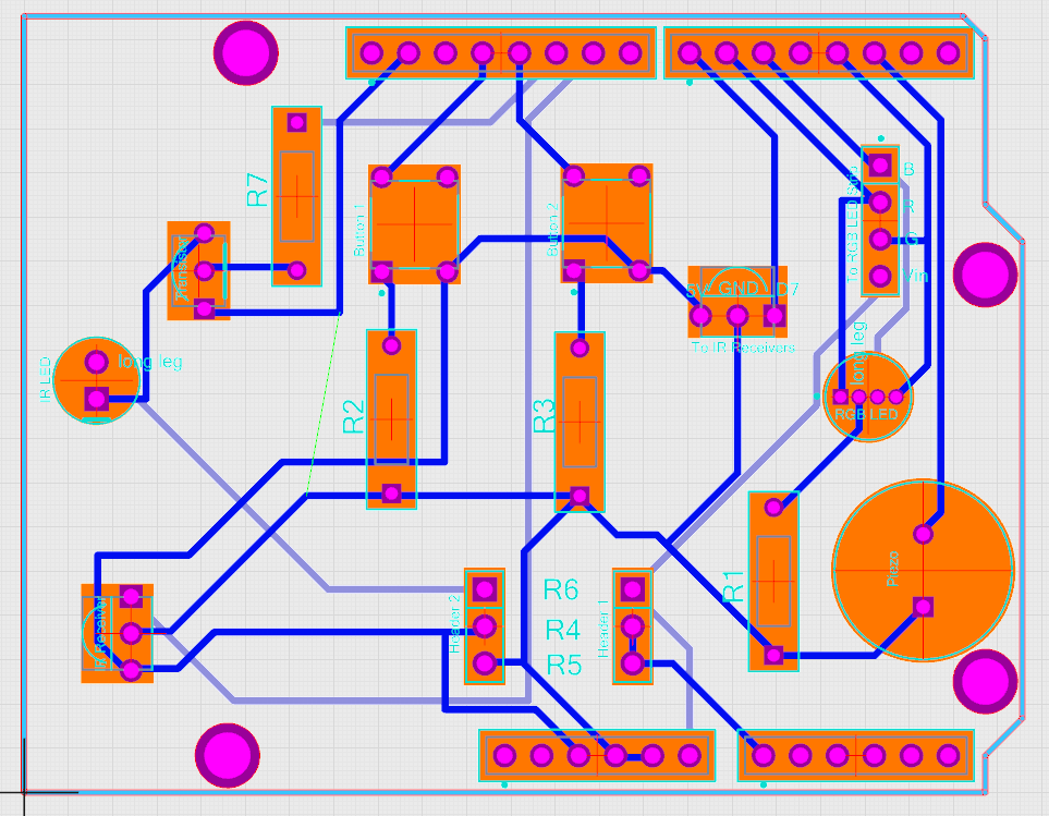
Arduino Shield
07/16/2020 at 14:15 • 0 commentsIt was relatively simple to put together an arduino shield using Upverter. They had an arduino shield template (fortunately, so I didn't have to make one), and I could fork off of that to make my own. It only took me a couple of hours to attach all the components in the schematic and then wire up the board.
![]()
I never actually learned how to do circuit design in class. It was something that I picked up by doing it. That's how you learn things sometimes. Not by reading it from a book or sitting in a lecture, but by actually doing it. There are some great tutorials out there on how to do it. Like this one that shows you how to make your own arduino shield, or this one that shows you how to make a simple circuit board.
Alas, I used to have this arduino shield in Fritzing, but when I dug up my old files and started to edit them, I realized just how annoying that software is. It was very hard to select individual traces on the board, and moving them around was near impossible. I spent an hour trying to move about three traces that were wrong, and eventually I gave up. Deciding it was easier to rebuild the entire shield in upverter than try to fix it in Fritzing. So I did. And it was.
I guess that's my internal lesson for myself. Use a good tool and this process will actually be pretty straightforward. While upverter still didn't have all the parts I was using in my design, it had most of them, and I could use parts that had the same footprint as substitutes.
Oh, yeah, if you copy the design, some of the components are incorrect. I didn't put the correct ones in, as they either didn't have them or it was easier to put in something else. The actual parts list is on my website, not Upverter.
-
Getting Started in Upverter
07/08/2020 at 14:41 • 0 commentsSo, I started making the printed circuit board versions of the laser tag kit in Upverter. Upverter is an electronic design automation tool, which can be used to design electronics. It's supposed to have lots of parts and have a concierge service where they will add parts that they don't have in their system. I decided to check it out.
I started with the headband / sensor package, as that is the easiest thing to make. As a note, I haven't done much PCB design. The only other PCB that I've made is an arduino shield in Fritzing. But, here is how this process went.
It started pretty well, with the first few minutes following their schematic tutorial. That tutorial was pretty straightforward, and I started setting up the schematic pretty easily. They didn't have the correct infrared receiver, but I sent it in to their "concierge" service to add it. They said it'd be done in 24 hours. Cool.
After setting up the schematic, I headed over to the PCB Layout screen to start putting together my circtuit.
And I immediately ran into a brick wall. I couldn't find the button for the second step in their tutorial. I had to Google search how to find it, as it wasn't straightforward where you actually clicked and went to change the board size. Maybe I just missed it, but I think tutorials should be very clear, as you are getting used to the interface and locations of everything.
A couple of gripes:
All of my resistors didn't show up on the PCB. They have "generic" parts you can use, but those parts didn't show up in my PCB layout. And, I didn't know of a path forward to add them. So, I just replaced all of them with real ones, and then it was fine.
I couldn't find the button to add text to the silkscreen. I checked their tutorials, but they've updated their software since then, so the button they used was hidden in a different menu. That was an annoying waste of 20 minutes searching for something that I couldn't find easily.
Finally, I never got the actual infrared receiver. Of the two components I cared about on the board (the transistor and the infrared receiver), only one of them was the correct part. I ended up using dummy parts for all the other parts. Oh well. Perhaps they will add the infrared receiver eventually, but I wasn't going to wait. They said 24 hours, and I waited 72 and still haven't seen it.
Overall, Upverter had everything I needed to make the PCB, but it didn't have all the parts and didn't have a clear tutorial for explaining some of what I think are basic functions. Could I get it to output what I needed? Absolutely. I sent the Gerber files to Osh Park to see if the board works. But it wasn't the "everything is here and is easy to use" result that it advertised itself as.
Open Tag
The best game of laser tag you've never played. Choose your class - from a sniper to a pyro, and customize your own game of laser tag!