DISCLAIMER: Tube circuits contain LETHAL voltages! Don't try to build this stuff if you don't know what you're doing!
Ever since I completed my tube power amplifier, I wanted to build a preamplifier to go with it. My power amp could handle line level signals, but I needed an RIAA phono stage. Instead of designing one myself I decided to use a PH-16 kit from tubes4hifi.com and create a custom enclosure to go around it.
I added the following features:
- a motorized volume control knob with remote control
- a nixie tube volume level and input selection display (for kicks)
- 5 selectable inputs
- 2 selectable outputs
- a passive "bass cut" tone control (so as not to annoy my neighbors) that could be disabled
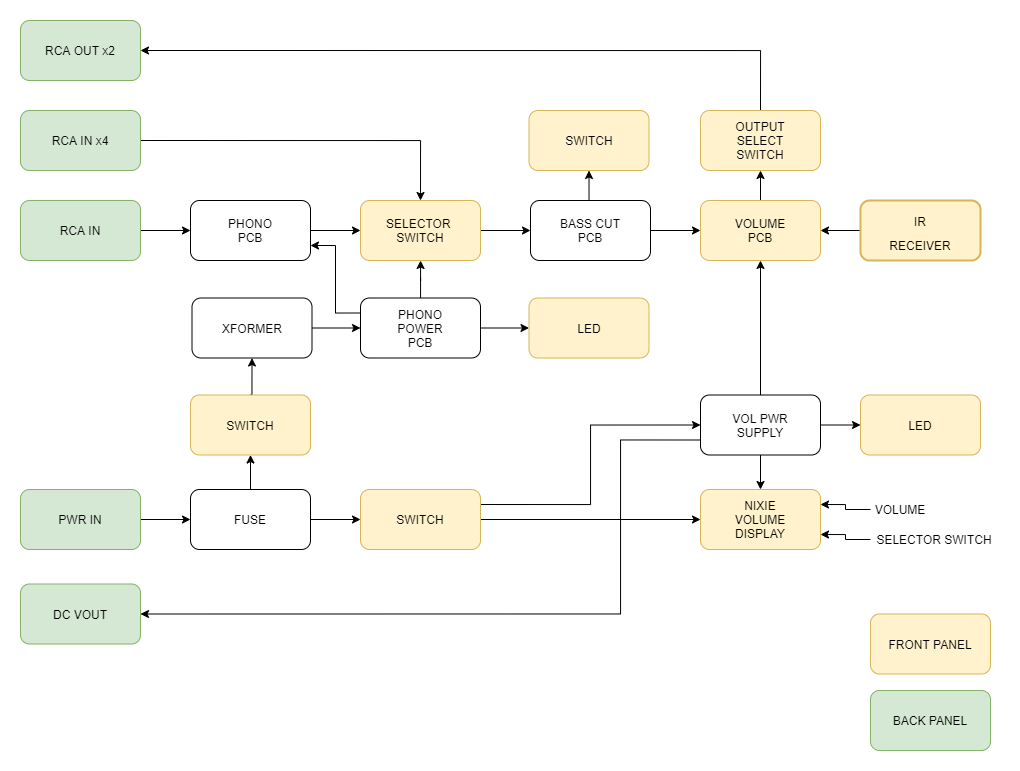
I started with a block diagram and panel layout:
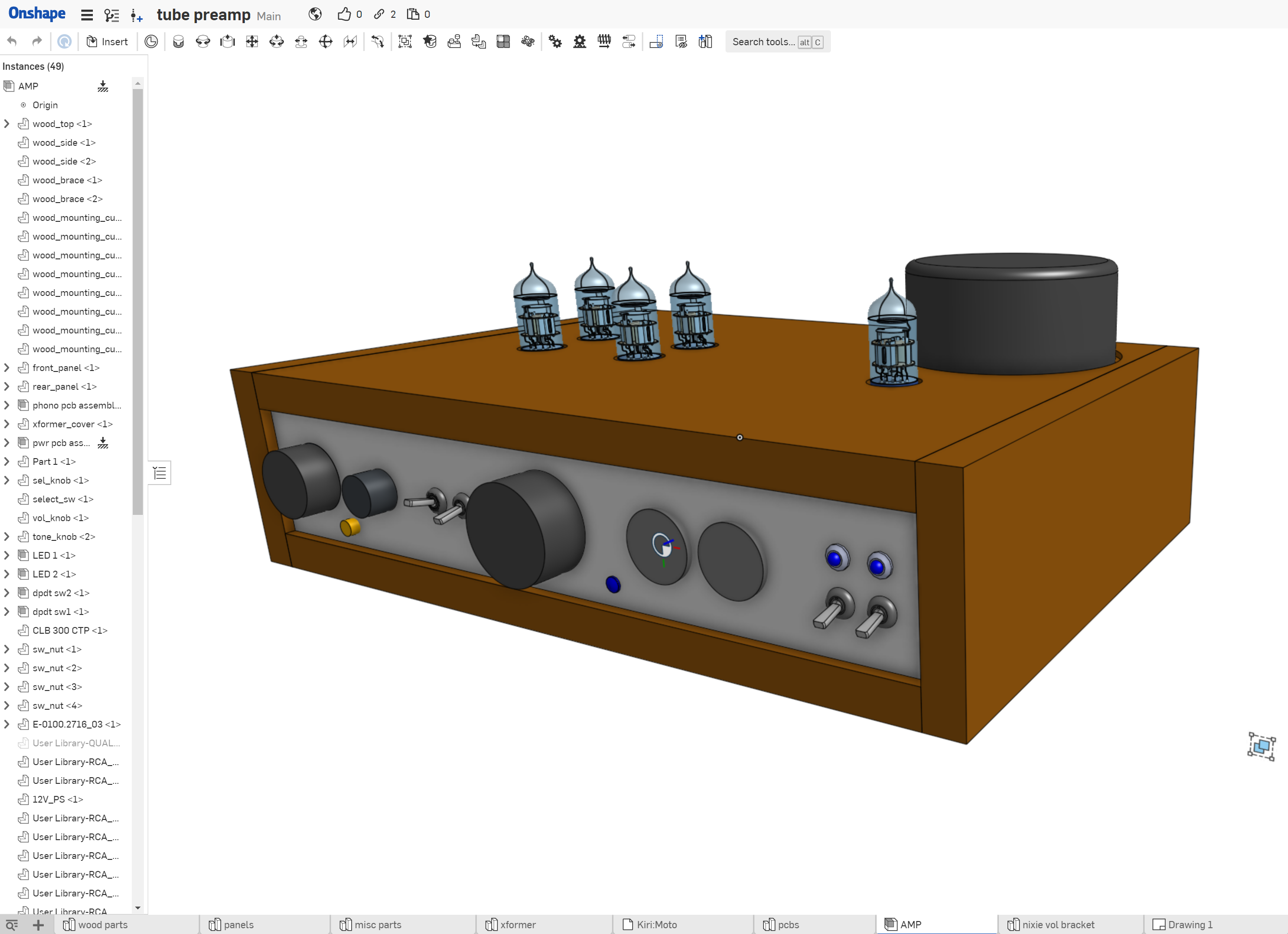
After selecting most of the components, I created a 3D model using OnShape:
As with my last amp, I enlisted the help of my father-in-law, who is an amazing woodworker, for the chassis. I created drawings in OnShape to send to him:
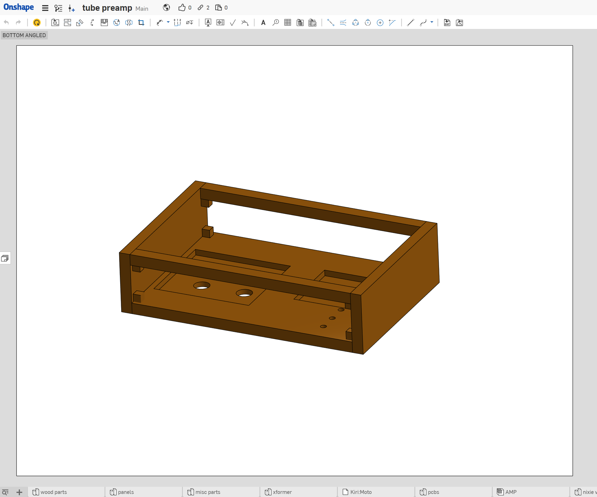
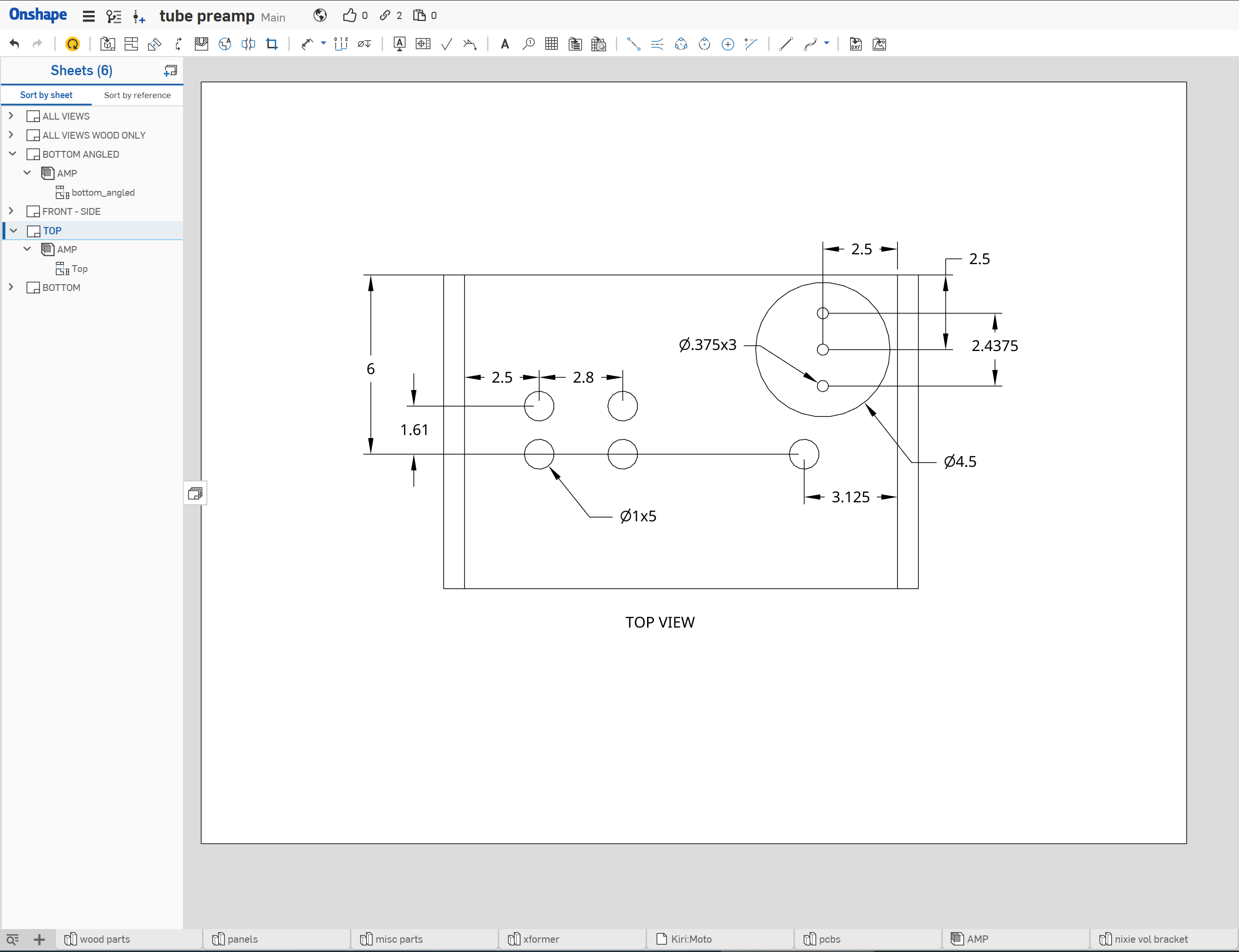
Here are a couple photos my father-in-law sent me of the woodworking process:
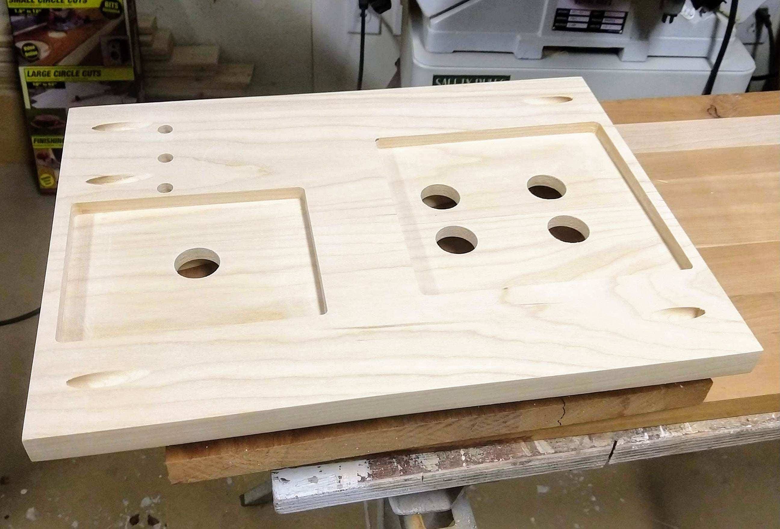
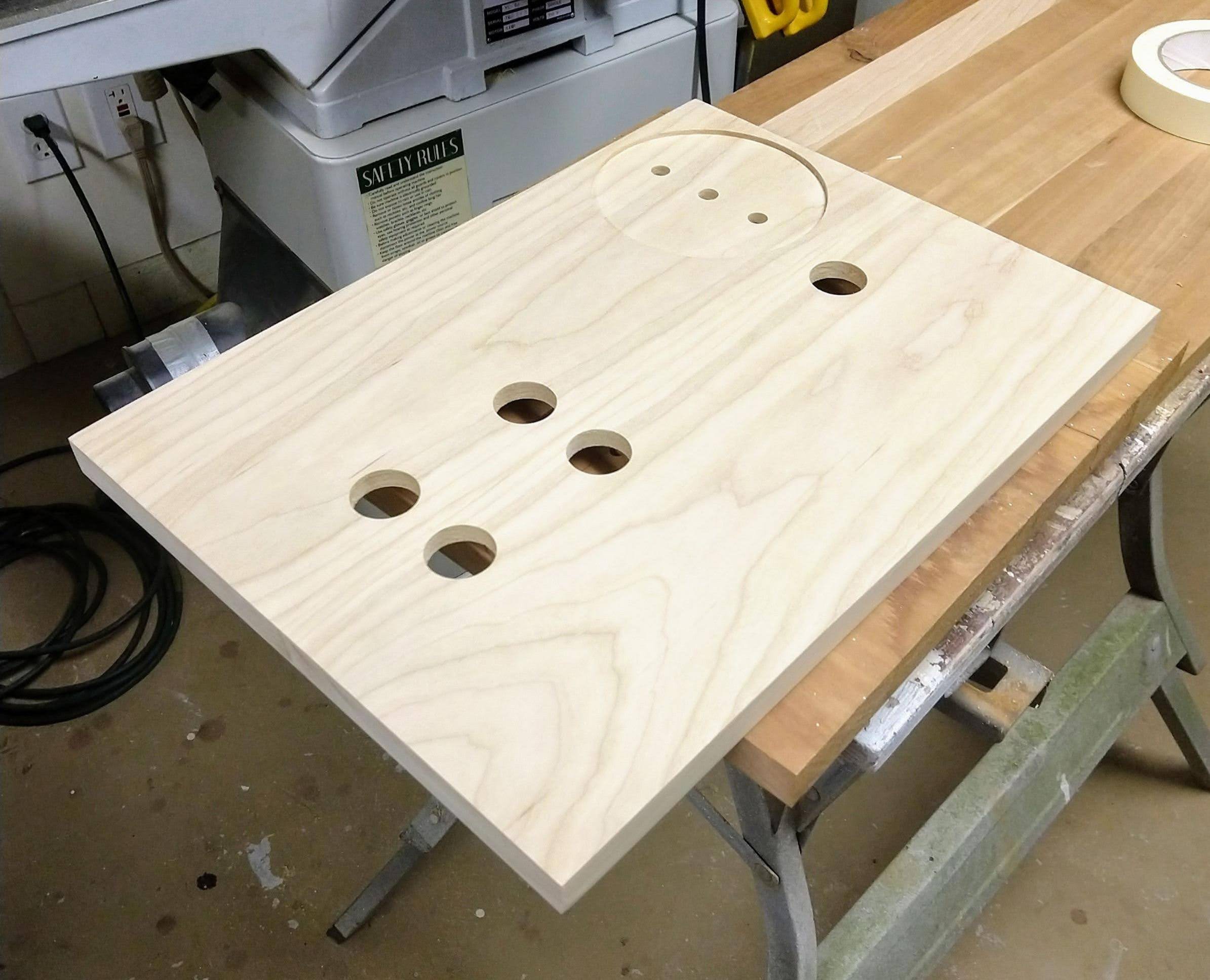
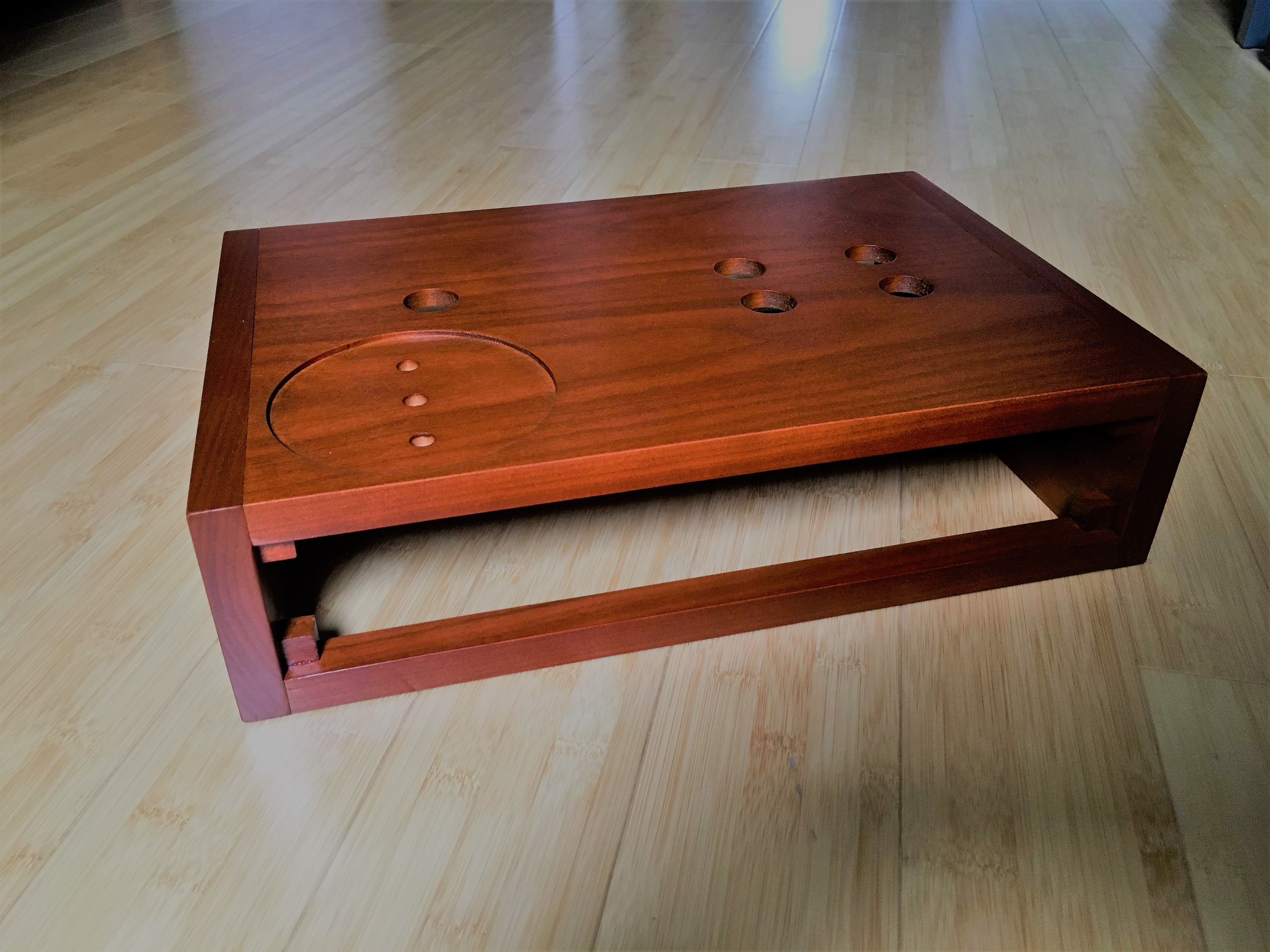
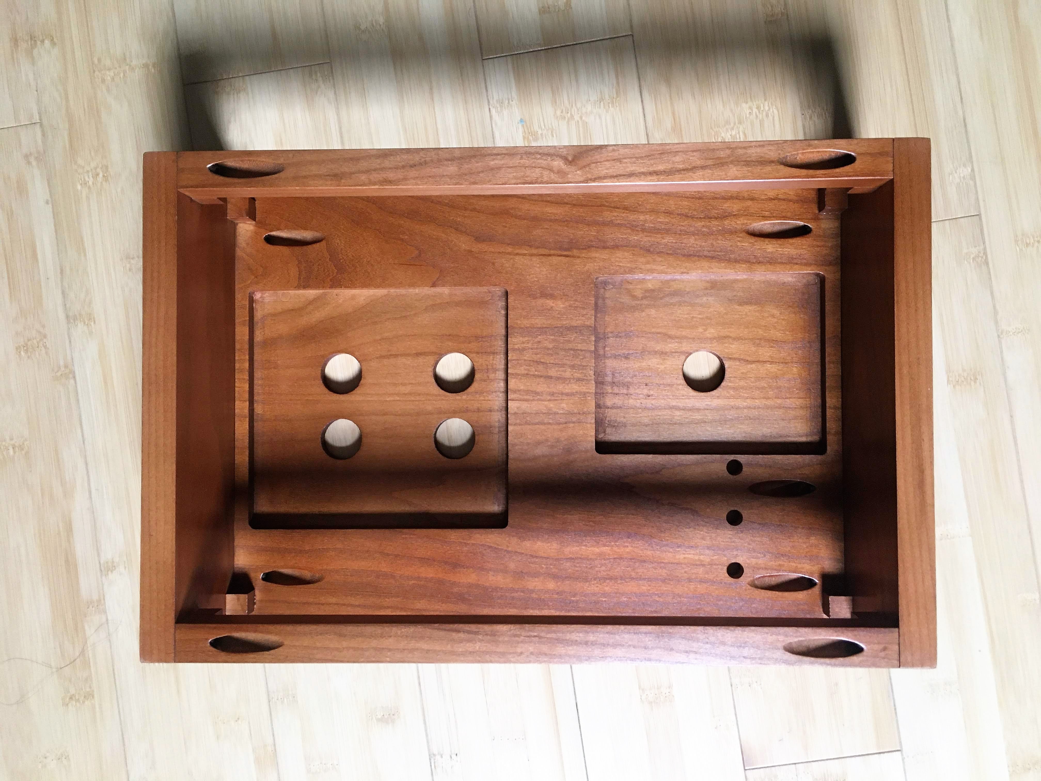
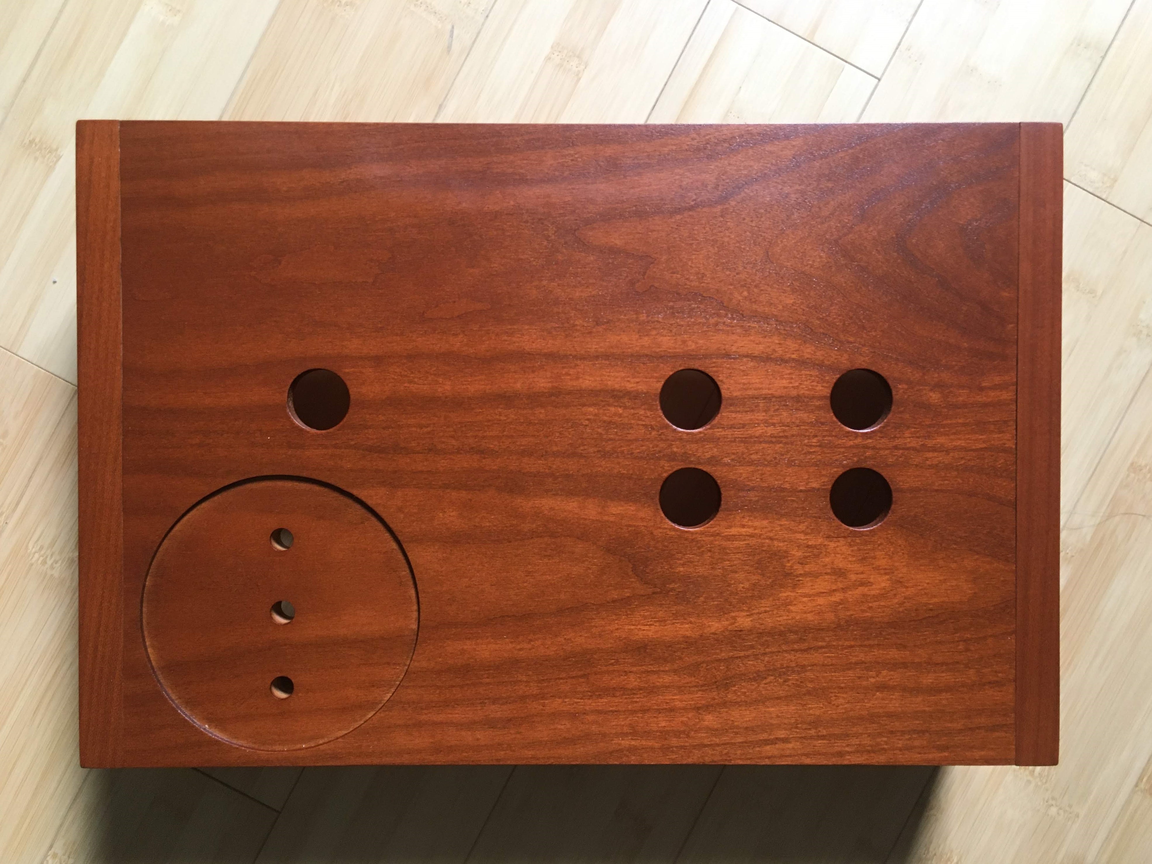
Just a few weeks after I sent him the drawings, I received this beautiful piece of cherry in the mail:
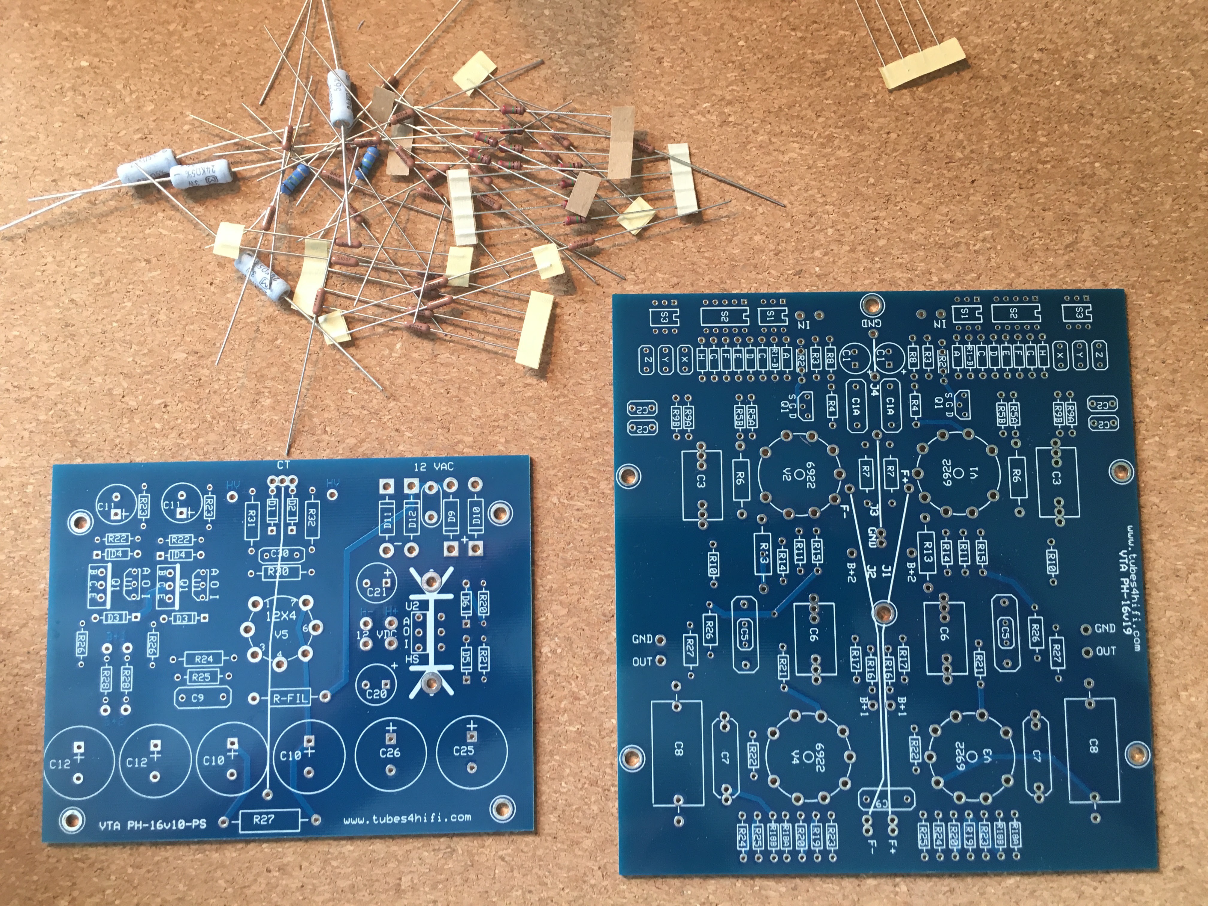
I ordered and received my PH-16 kit from Roy at tubes 4 hifi. Roy is the genuine article: friendly, helpful, and a joy to do business with. Here are the bare PCBs:
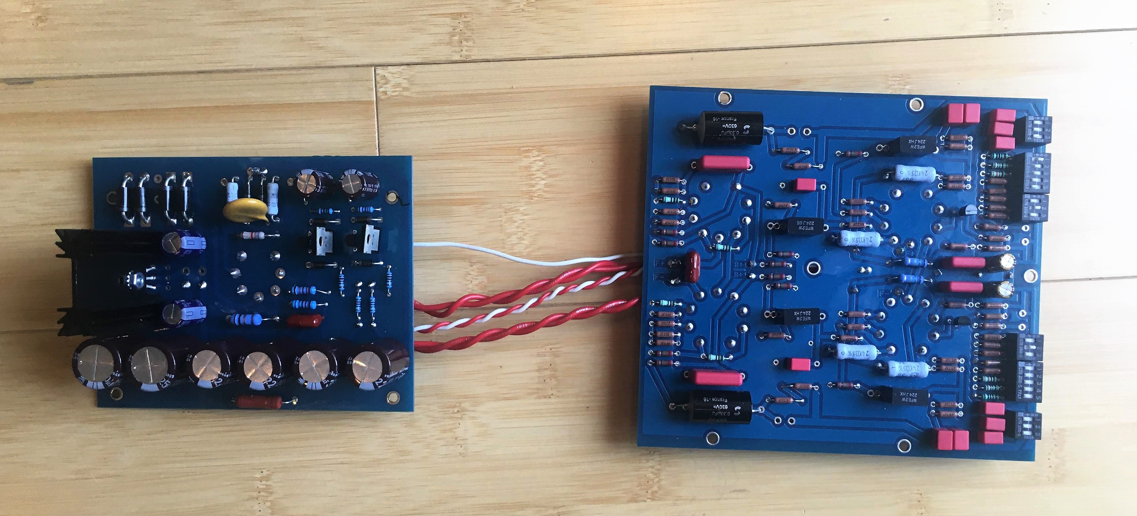
And here they are after I populated them and wired them together:
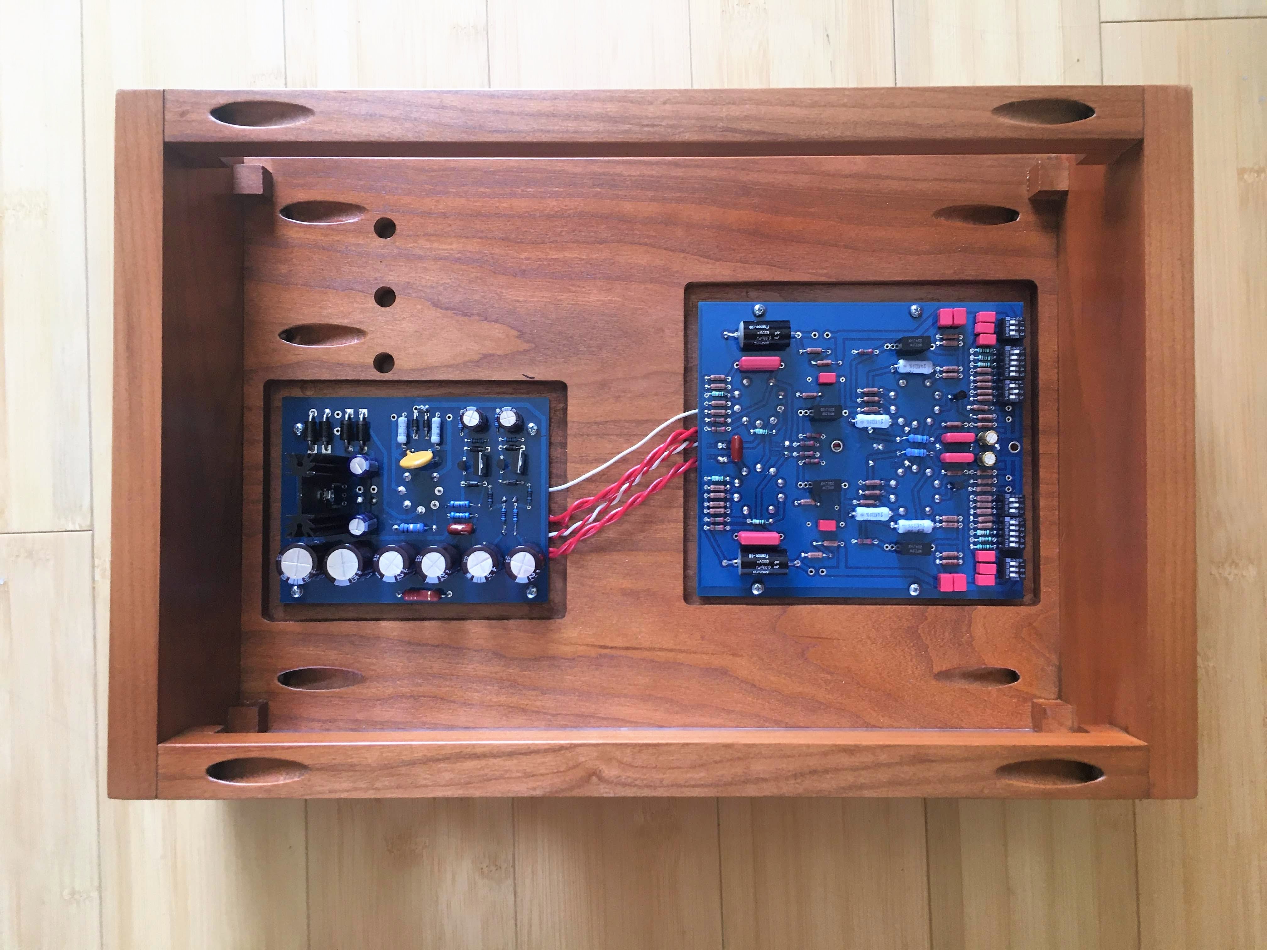
And installed them in the chassis:
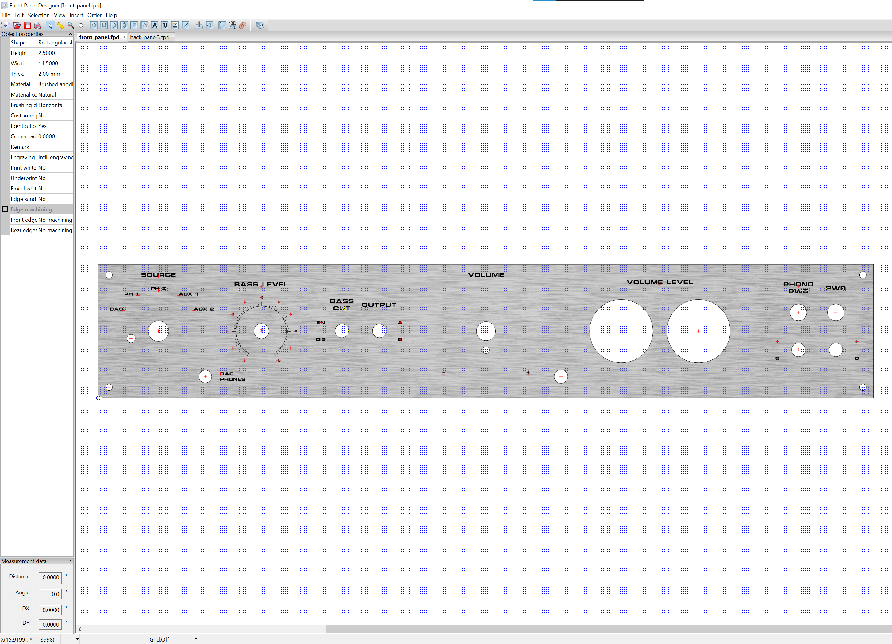
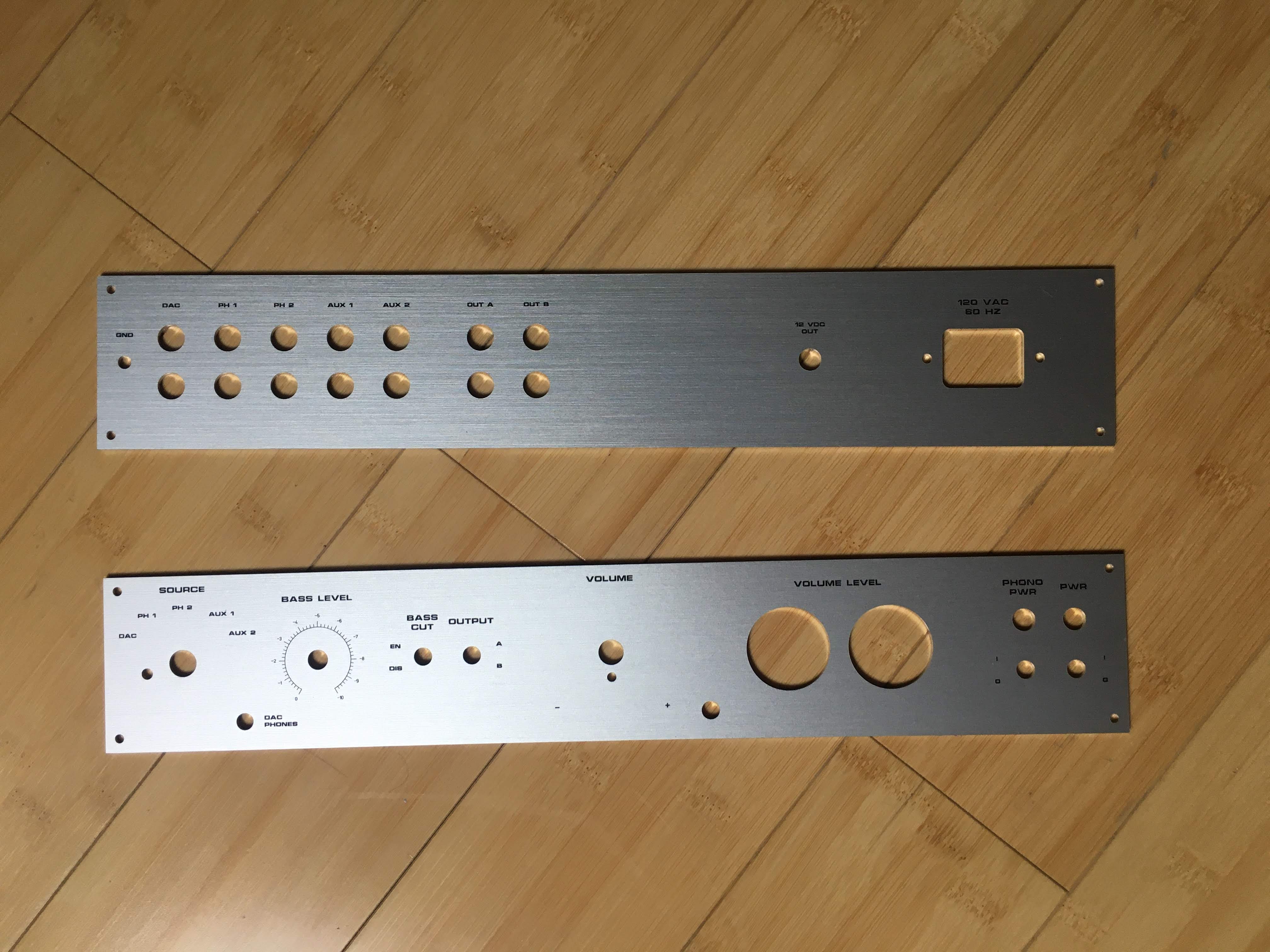
I used Front Panel Designer from Front Panel Express to design the engraved front and back panels from brushed aluminum:
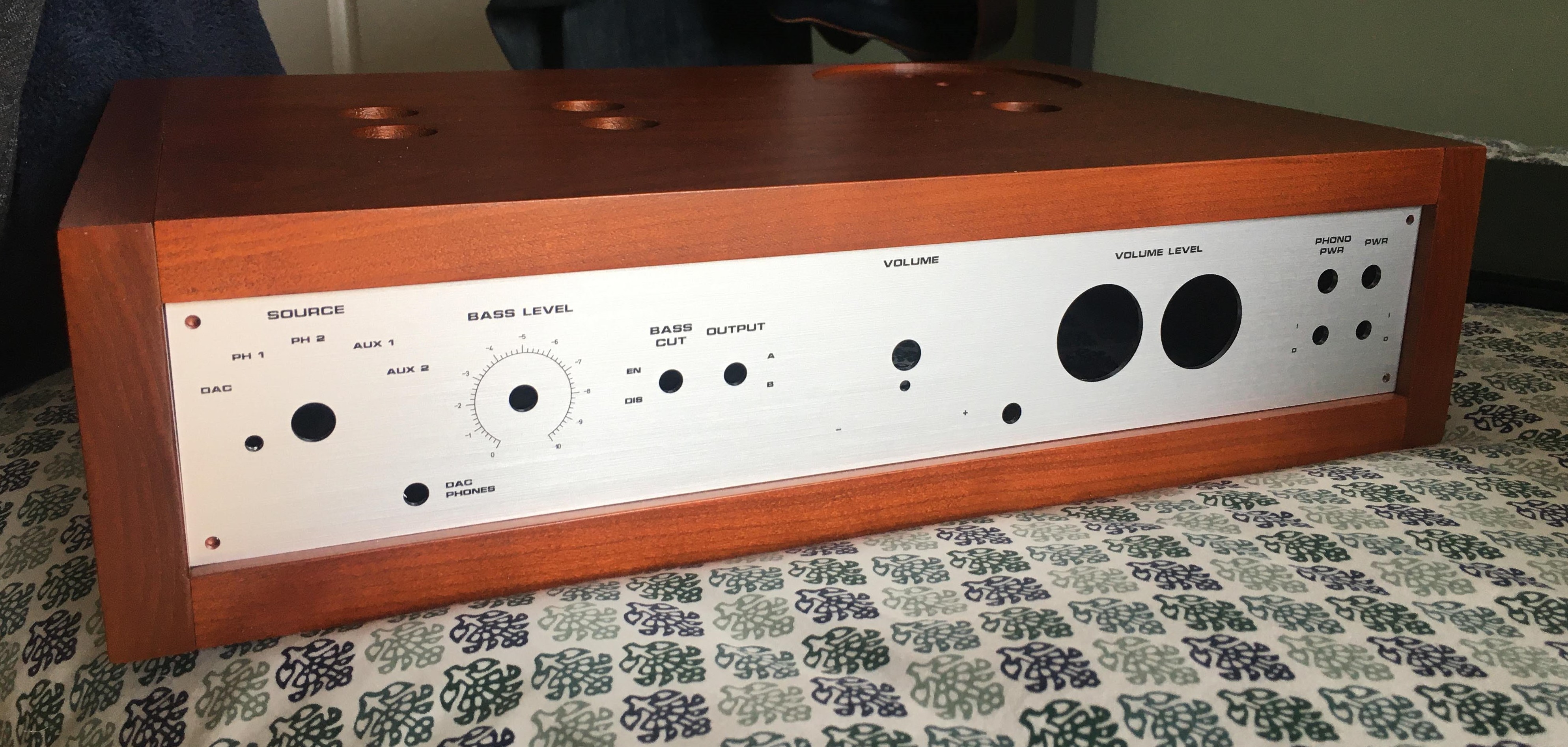
And here they are once I received them:
For the remote volume control, I bought a bought a board off of eBay that comes with a remote control and a PCB with a motorized volume potentiometer (pot):
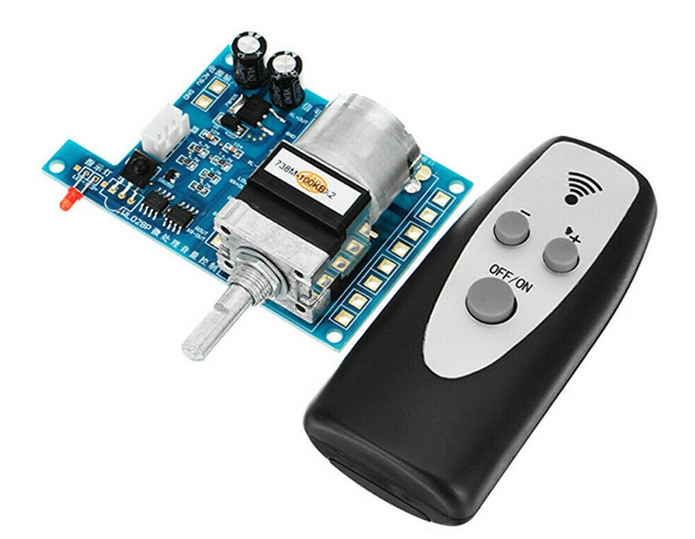
The board came with a Panasonic motorized pot, but I replaced it with quad 100K logarithmic Alps one.
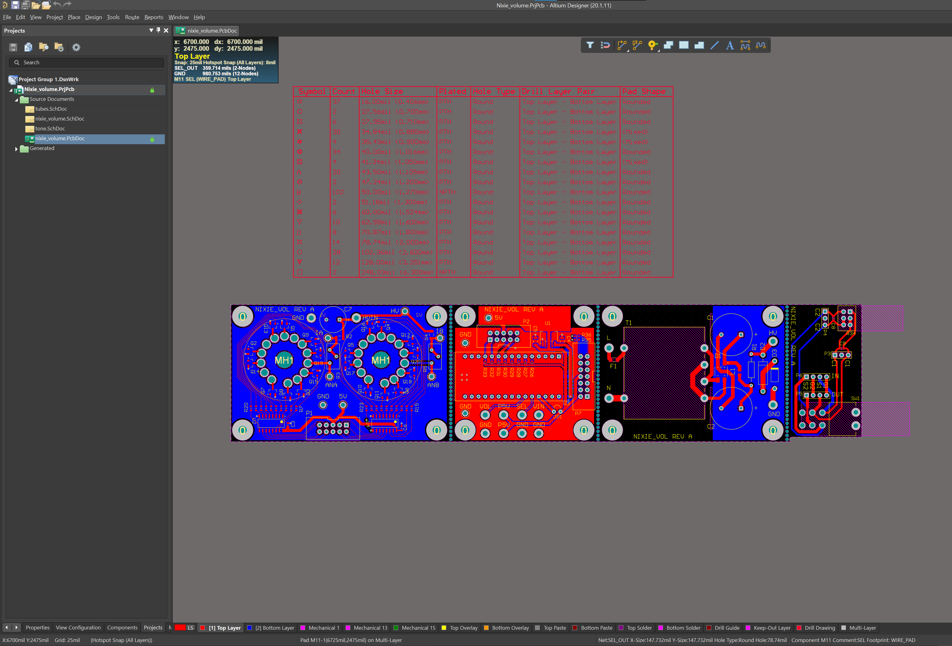
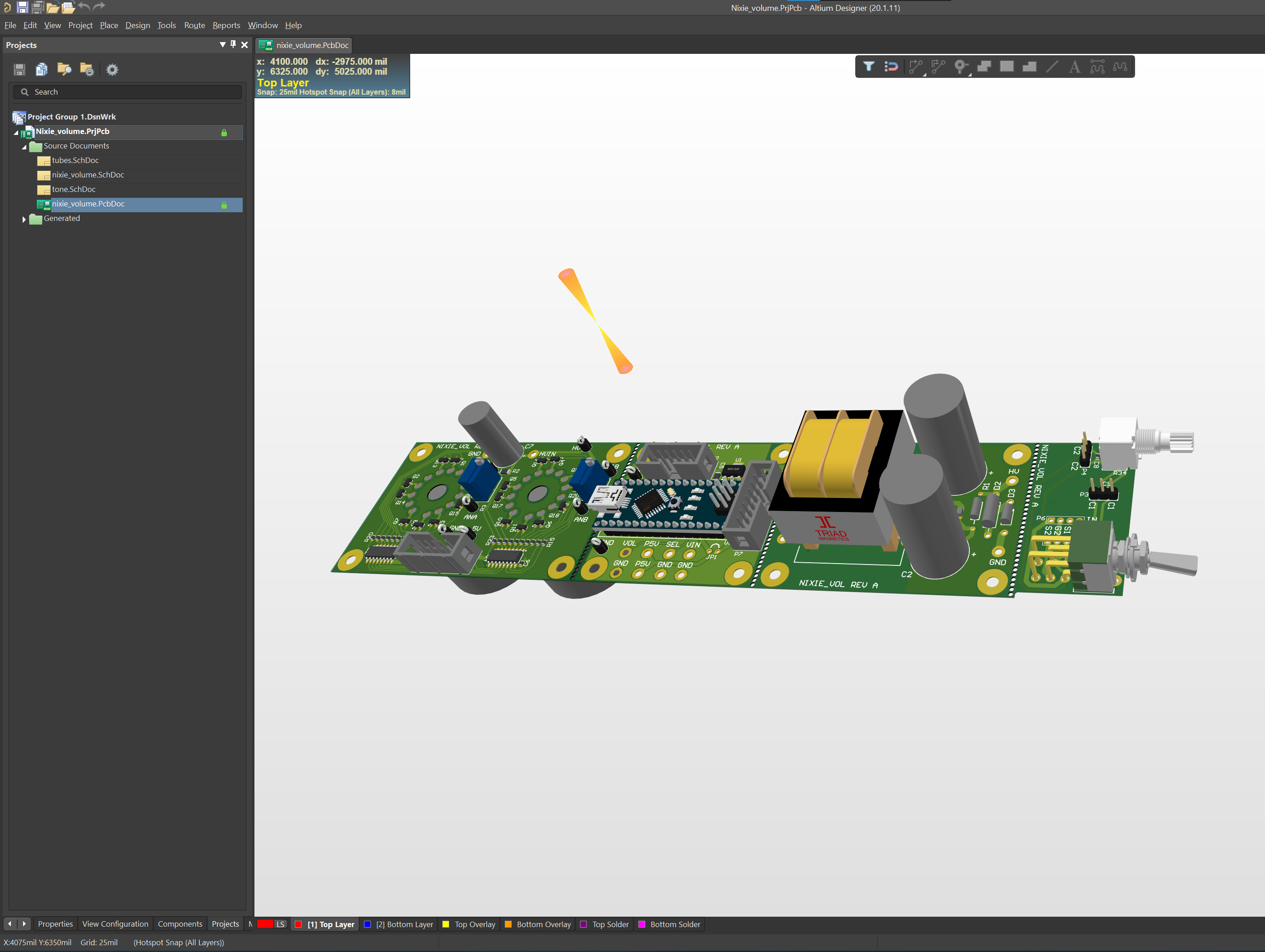
I designed four PCBs in Altium Designer (I have this for work; I'm not rich enough to own it myself) for the nixie tube volume display. One was a linear 170 VDC power supply for the two IN-4 nixie tubes I purchased on eBay. The second was a board to hold the nixie tubes and transistors for turning them on/off. Third was a small board to hold the parts for the bass cut filter. Fourth was a breakout board for an Arduino Nano.
The volume display works as follows. An extra channel of the volume pot is hooked between the Arduino's reference voltage and one of its analog inputs. The Arduino constantly polls this input and updates the nixie display depending on the voltage it reads. The Arduino is interfaced to two CD4028BM96 BCD-to-decimal decoders, one for each tube. These turn four IO lines from the Arduino into 10 outputs. The decoder outputs are each connected to 10 MMBTA42-7-F transistors that switch each of the tube's filaments to display numbers 0-9.
Here is the PCB layout in Altium (I combined all four PCBs into one in order to save money):
And here are the PCBs once I got them back from JLCPCB and separated them:
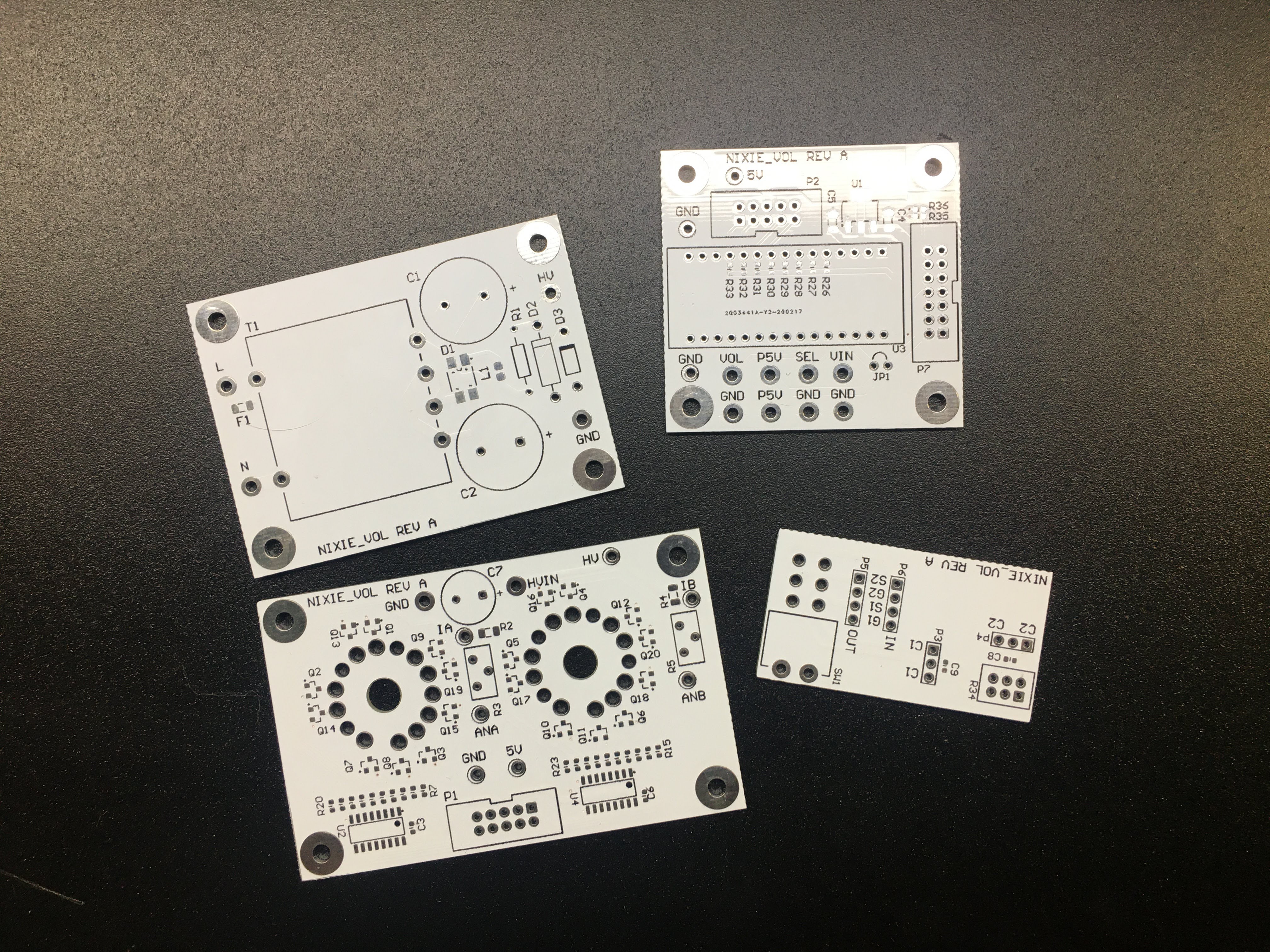
Inevitably, mistakes were made. I had to respin the nixie tube and bass cut boards, so you'll notice they are red and black (respectively) in photos that follow.
Here is a short video from after I built the boards, wrote the code, and debugged everything:
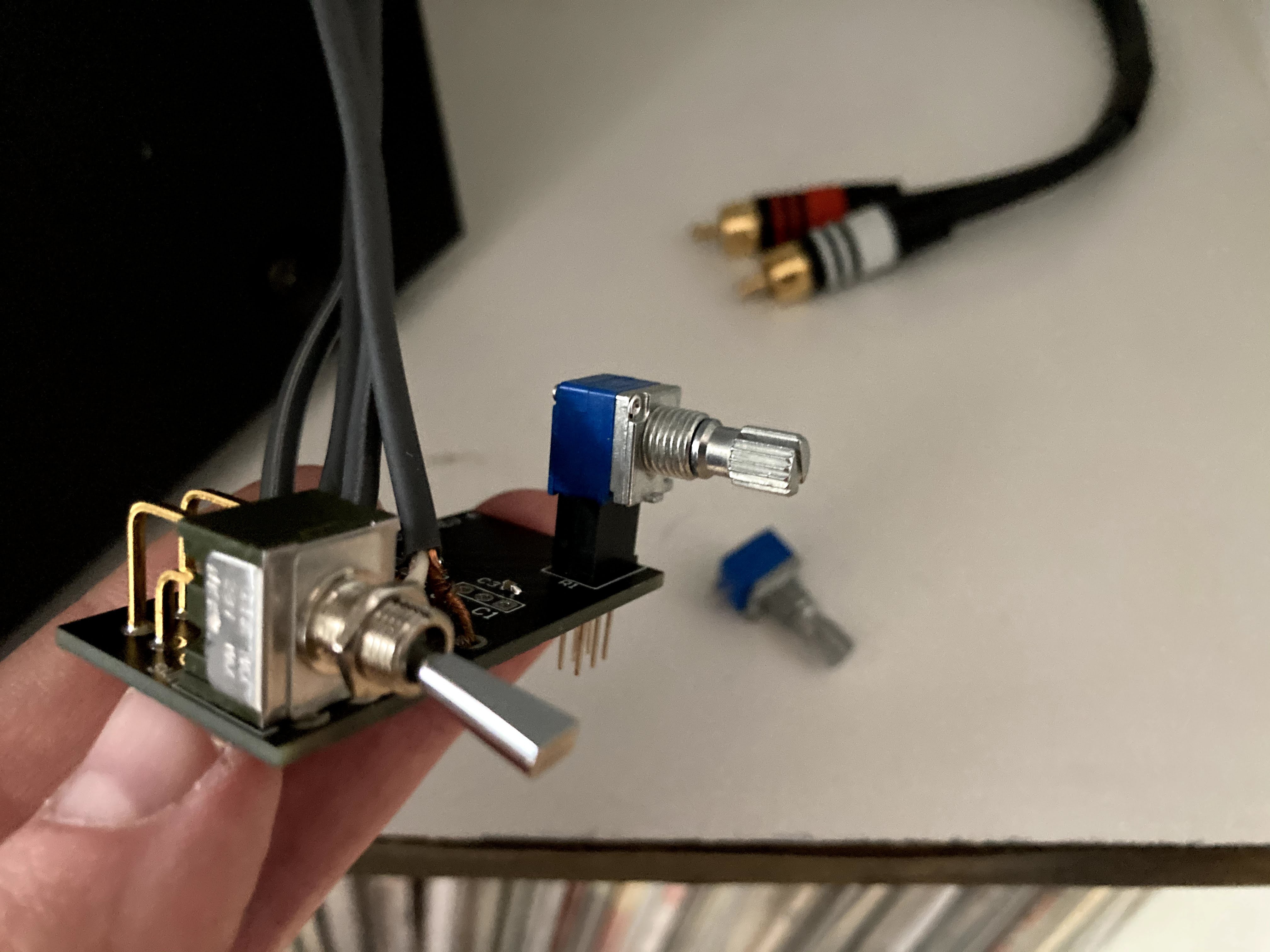
Next I built the bass cut board and tested it. The signal for each channel is run through a 10 nF capacitor in parallel with a pot that is configured as a variable resistor. A switch is placed in parallel as well, so I can short out the filter and disable it. Here is a photo from the filter testing:
Once that was done, I wired up the input selector switch. I had a quad pole switch, so I connected resistors between the throws on one of the extra poles to create a big, selectable resistor divider. I ran this over to an analog input on the...
Read more » Justin Scott


Gorgeous result! What did you use for the little round IR window?