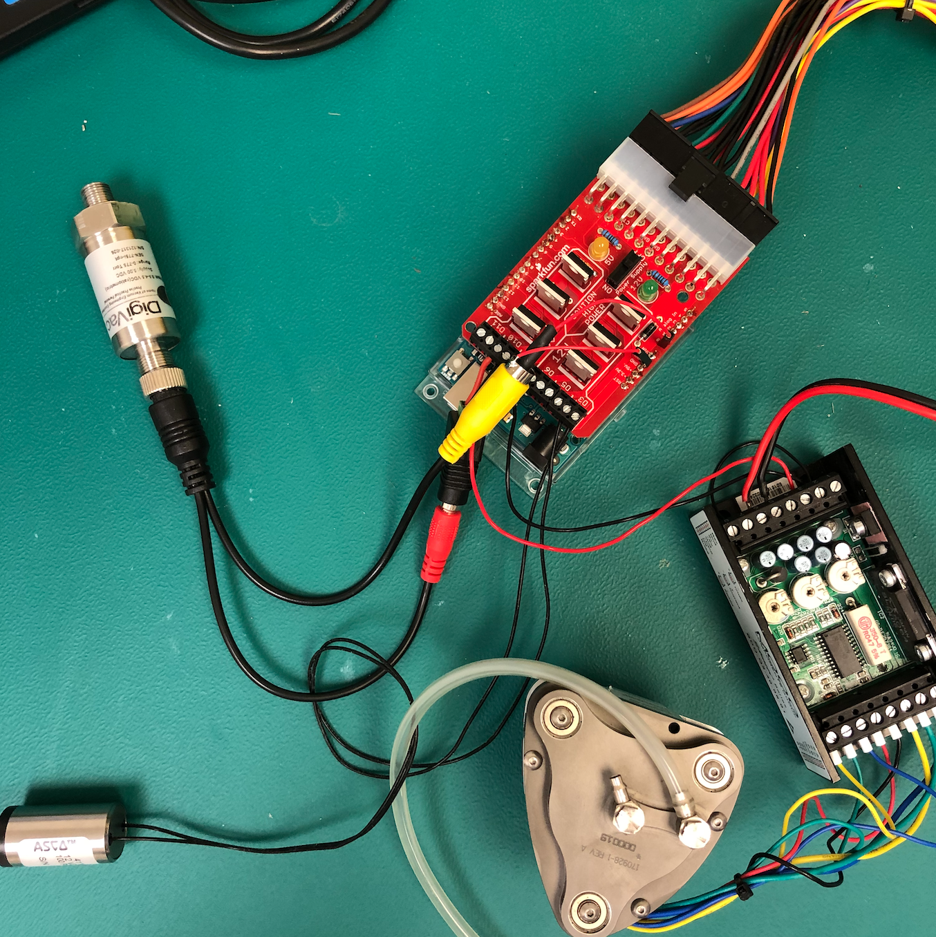
For the National Science Foundation project "SBIR Phase II: A spectroscopic THz Sensor for Mixed Gas Analysis and Air Pollution Monitoring"
To make the experience fit your profile, pick a username and tell us what interests you.
We found and based on your interests.
PowerDriver-Shield-v13.pdfSchematic for the arduino shieldAdobe Portable Document Format - 34.47 kB - 06/19/2020 at 18:27 |
|
|
This week, I've been working on upgrading the system by adding a Raspberry pi 3. The goal is for the Rpi to tell the Arduino to maintain the chamber at a specific pressure based on the needs of the current mission, and by listening to data readouts from the Arduino, the Rpi can respond with more commands accordingly. I'm using an I2C connection between the Rpi and Arduino, as the USB port will not be easily accessible when the system is housed in the chassis and is not secure enough for flight.
I've configured the Rpi to send data over the I2C connection, and tested this with a simple Python code to turn on and off the Arduino's onboard LED.
I'm now exploring another simple code in which both the Rpi and Arduino send information to each other (the Rpi sends a byte, and the Arduino sends a byte in return). For this, I'm following the example code on this web page: https://roboticsbackend.com/raspberry-pi-master-arduino-slave-i2c-communication-with-wiringpi/ However, Python tells me I have a syntax error in the first line {int main (int argc, char **argv)} even though I copied it verbatim from their example!
Once I solve this syntax problem, the real challenge will be figuring out how to write both the Python and Arduino codes to perform the tasks of operating a vacuum pump, opening and closing a solenoid, and reading a pressure sensor in order to regulate the pressure in the vacuum chamber. I don't have much coding experience myself, so any suggestions for first steps would be extremely helpful!
Also, I created this simple schematic (which I've added to the images for this project) which shows how the various boards and devices are connected. We will be creating a custom board which integrates all these boards into a single board.
We've figured out how to operate both the solenoid and vacuum pump brushless motor from different pins on the same Arduino shield! The motor can simply turned on or off by supplying 5V from a MOSFET on the Arduino shield.
As for the pressure sensor, we've connected the positive lead to Analog pin 0 and ground to ground. We're using a code which either opens or closes a solenoid depending on whether this voltage on pin A0 is greater or less than 5 volts. When running the system at atmospheric pressure, the solenoid began sputtering wildly. We're not sure what the voltage scale on the pressure sensor is, so we don't know whether we should expect the solenoid to be open or closed at this pressure. We're considering using the serial monitor in Arduino to see what voltage is being supplied from the pressure sensor to the pin at this pressure.
The 12V solenoids have arrived and are operable from my current setup! I've written an arduino code in which the solenoid opens only when a voltage input passes a certain threshold. This means that, when the pressure sensor arrives, the system can be set up such that the voltage output from the sensor can operate the solenoid.
We are also trying to determine whether we can operate multiple arduino shields running different codes from the same arduino UNO board. Both shields use pins in common, so it may not be possible to run code to both at once. Does anyone know whether it might be possible to run two different codes to the shields, if it is done not simultaneously? For example, a code could be run to one shield to open the solenoid, then immediately after, another code could be run to the other shield (which operates a vacuum pump) to pump gas into the chamber? Any thoughts would be appreciated!
I've created an arduino code to switch on and off the solenoid (a modified blink.io code). Right now the board outputs a maximum of 12V, and my Solenoid is 24V so isn't operable by the board. I tested the board on a smaller solenoid, though, and it started opening and closing! I tried wiring two of the arduino shield's output ports in series, but the voltage remained at 12V.
Next steps are to order a 12V solenoid and a pressure sensor, so that the solenoid can be autonomously opened or closed by the arduino depending on the pressure in the chamber. I plan to use a DigiVac Model 276 (BASE) vacuum gauge which includes a thermocouple vacuum gauge combined with a piezo sensor. Any insights on creating an arduino code for operating this system would be appreciated!
Create an account to leave a comment. Already have an account? Log In.
Hi @Thomas Logan what sort of connection guidance are you after? I have looked at the solenoid website and the information I would be wondering is if it can be continuously operated. At 2W /12V = 160mA this may or may not be an issue (and I couldn't see how long you want it on for).
The other thing which is probably not a concern but perhaps worth knowing if you haven't used MOSFETs before is that the low voltage wire of the solenoid won't be at the same potential as the power supply ground. The slightly higher potential of the solenoid low side is dependant on the voltage drop across the N channel MOSFET, which in turn is dependent on the MOSFET's "on resistance" (0.04 ohms roughly) and the current you're passing (0.160A x 0.04 Ohms = 0.0064V). In this case, 6mV isn't likely to be significant but larger currents or a different MOSFET might change this. If you need to ensure that your load low side is at the same potential as the power supply ground, you can use a P channel MOSFET on the high side of the load.
When you get your power supply, you may want to do some speed testing to see how quickly your solenoid actuates. You should be able to use your arduino to do this, depending on how easy it is to sense when the actuator has opened (maybe its shaft could press a button or the valve opening could allow a light beam onto a sensor). If your solenoid is slower than you want, you may be able to find a faster one, or overdrive it (but the magnetic field changes are likely to be the limiting factor). Maybe you can adapt the opening time to account for the opening and closing ramps (pressure drop across the valve).
Let us know what questions you have anyway.
Also, @Thomas Logan the solenoid you linked to seems to be different from the one in your picture. Picture is labelled 24V / 30mA and link is to 12V / 160mA?
The 24V one might not work as expected because your shield will connect the high side to 12V - only half the rated voltage.
Would be helpful to know the spec of the one you have.
Hi, thank you for your comments! My power supply arrived, and I'm going to run the code on the board and use a multimeter to measure what the output voltage is before hooking up the solenoid. I might end up wiring the solenoid to two of the board outputs in parallel to get 24V rather than just 12V. Right now I'm struggling to find a code to run on the arduino for this specific shield; there isn't much information online. Any help would be appreciated!
@Thomas Logan do you have a clear plan for how you would connect two 12V supplies in series while supplying 5V to the control logic and keeping the microcontroller boards at the correct potential?
It's probably worth seeing if the board can be modified to operate at 24V and only require a single 5V controller.
------------------------
EDIT: so looking at the schematic it seems that you could wire a 24V supply (and never connect your ATX power supply at the same time) if you remove diode D1, which connects the 12V (24V) rail to the Arduino's 5V voltage regulator. You would have to provide power to your Arduino through its USB cable if you did this but I don't think that will be a problem for you (5V USB battery pack or have it plugged into a USB hub or phone charger). If you can double the value of resistor R8 to say a 2.2K ohm it would keep the yellow LED2 current the same as the 1K ohm resistor currently in there. There's a small chance you'd feed it too much current by keeping the same value but it's unlikely (24V / 1000 ohm = 24mA which is tolerable for most 5mm LEDs and that excludes the voltage drop of a couple of volts across the LED, so is conservatively high).
As far as code goes, how fast do you want to pulse this thing and what else does the Arduino need to be doing or synchronising with? If it is standalone and not straining the limits of the 16MHz-clocked ATMEGA328P chip, you should be able to change the pin number in the Blink.ino sketch to either 3, 5 or 6 and switch the 12V (24V) MOSFETs on and off with digitalWrite() and delay(). Fancier timing, synchronisation and tending to other roles means more complicated code but it sounds eminently doable.
Please only make changes to the board to add 24V if you are comfortable doing so at your own risk (mainly of damaging components rather than harming yourself but lets leave the definition broad!). May be worth checking with someone else at your lab or doing a project log and asking for help to check your work through a link to the log in the .stack. https://hackaday.io/stack
Cool project. I'm interested in that spectroscopic technique too - any references?
Try here https://hackaday.io/project/11634-the-thz-drone-project this is a good starting point for what we are doing at Bakman Technologies. We are not doing FTIR, but THz spectroscopy.
Become a member to follow this project and never miss any updates
By using our website and services, you expressly agree to the placement of our performance, functionality, and advertising cookies. Learn More
I realize this might mean you would have to possibly buy more stuff. I am working on something to be able to supply helium to a helium ballast transferred to and from a tank containing helium. I want to be able to reclaim the helium when I "dock" or am done with the vehicle. Maybe just use a 12v controlled solenoid valve. Have to check the amp usage compared to amp output on the 12v output of your PC supply. This lets you use the ardinuo on the 5V then use a single channel relay to apply the 12V to the 12V solenoid. Here is a link to the type of solenoid valve that I am referring to, you don't need to use this if it doesn't work per the wattage, but just an idea. This will also keep the code simple so that you can use a simple LED and momentary switch to develop your code with. https://www.ebay.com/i/264341833148?chn=ps&norover=1&mkevt=1&mkrid=711-117182-37290-0&mkcid=2&itemid=264341833148&targetid=917185845248&device=c&mktype=pla&googleloc=9017022&poi=&campaignid=9343999179&mkgroupid=103102860388&rlsatarget=pla-917185845248&abcId=1139336&merchantid=138358086&gclid=CjwKCAjwrvv3BRAJEiwAhwOdM0cXUM2u4e-tnUwjuxGWED5j1PdlxoGZ3_zABQsXTkDfcM3uxTg07hoCpoMQAvD_BwE