-
IR Temperature Sensor Measures IV Fluid Through IV Tubing
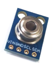
01/12/2021 at 03:21 • 0 commentsI finally got around to testing the GY-906 BAA IR temperature sensors. The test results indicate that measuring the temperature of IV fluid through IV tubing is not only possible with IR temperature sensors but also can likely achieve something close to +/- 1°C accuracy! I was pleasantly surprised and this was such a great way to close out this project.
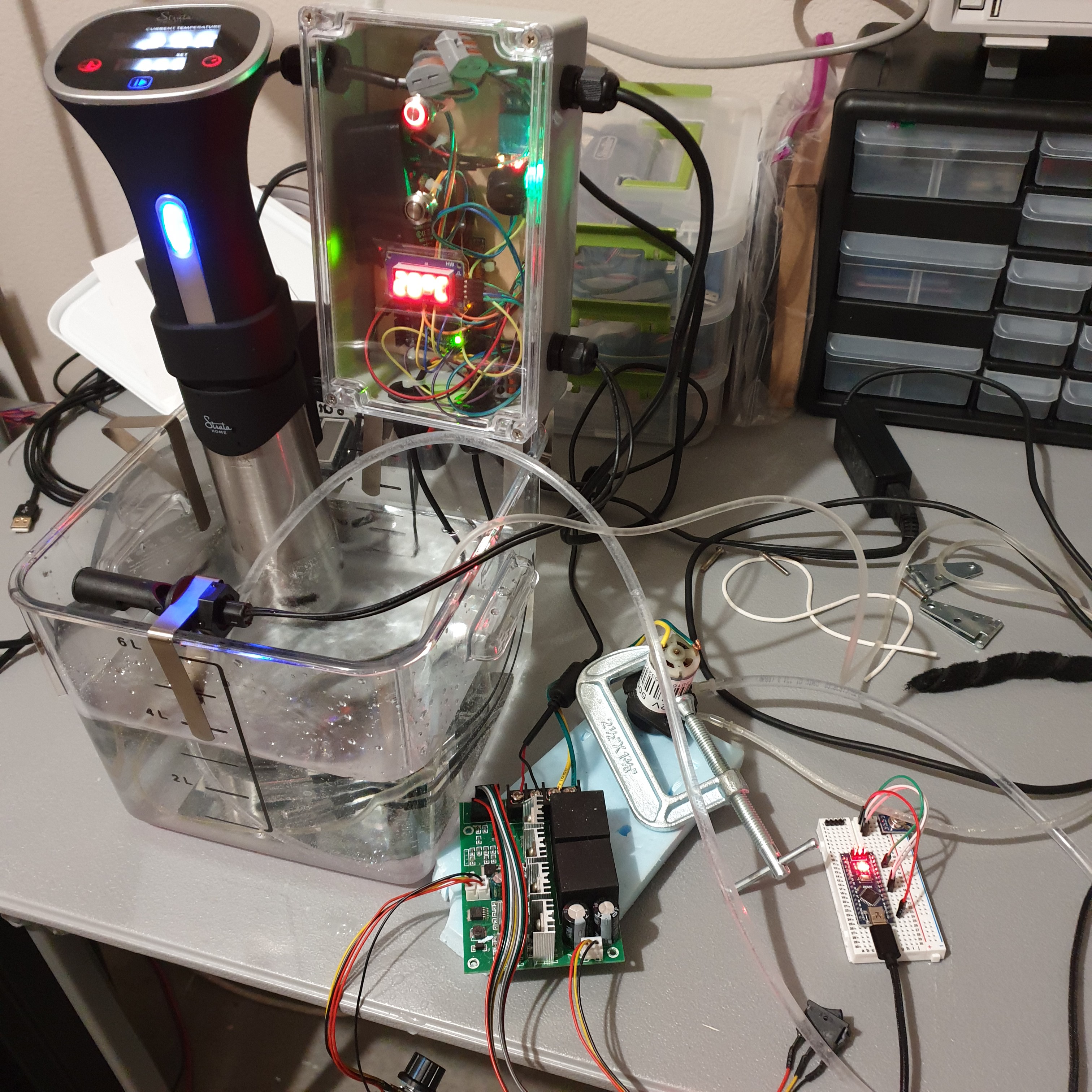
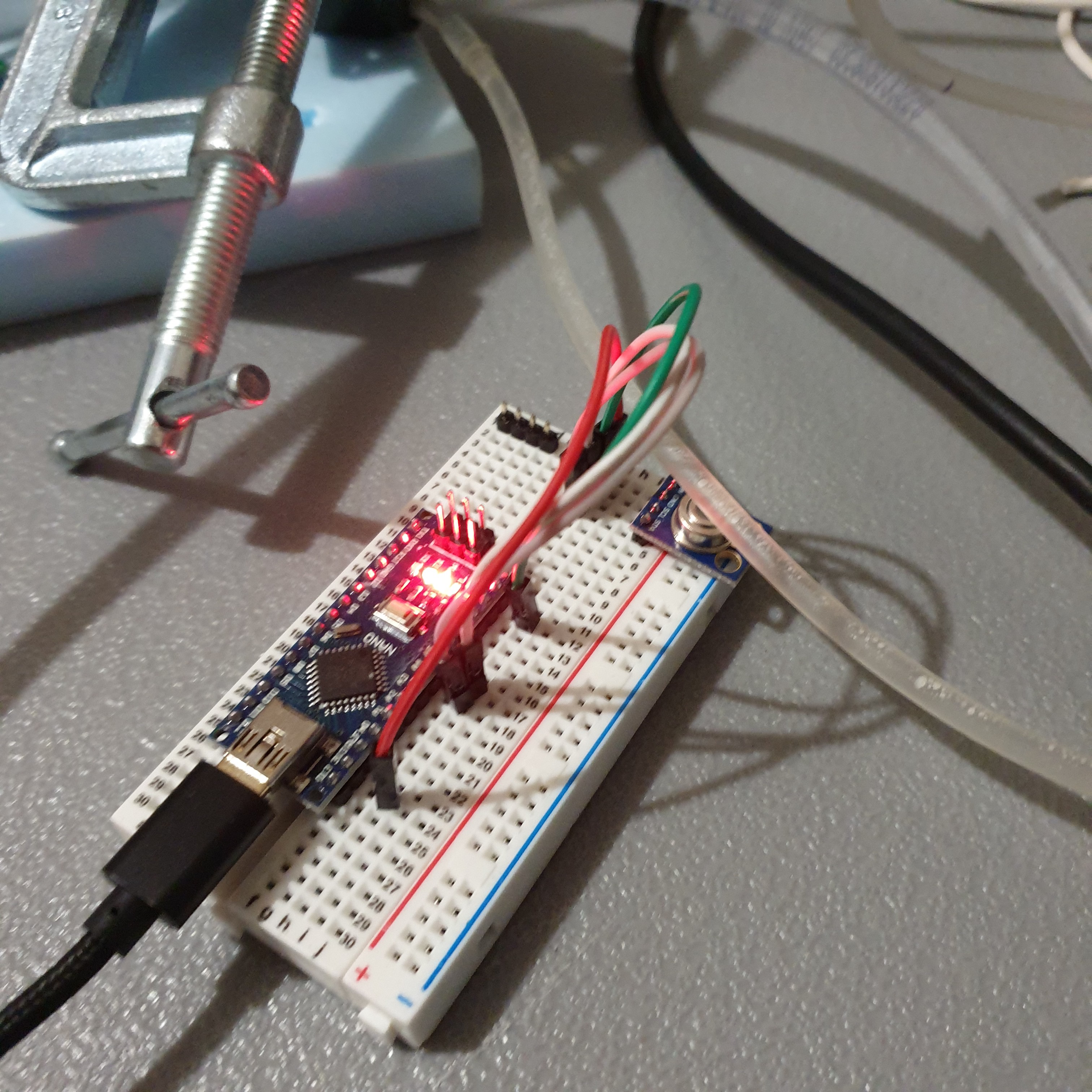
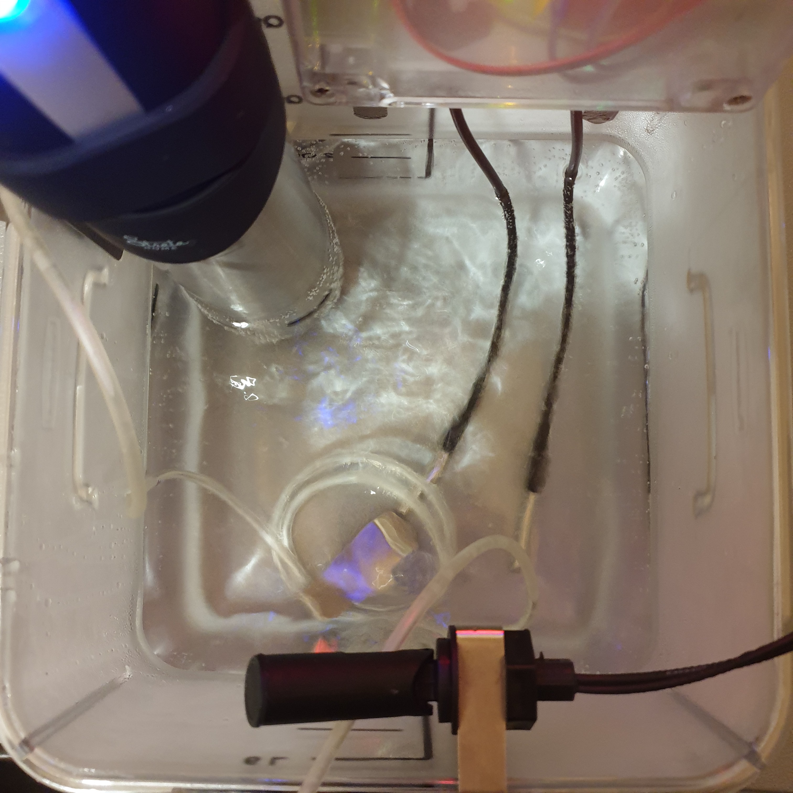
Testing of the IR temperature sensor involved using the sous vide cooker to warm water to several different temperature setpoints then pump the water through an IV tube and detect the temperature using a GY-906.
![]()
To get a good reading from the IR temperature sensor, I had to place the IV in direct contact with the senor and apply a very small amount of pressure on the IV tube to push it against the sensor.
![]()
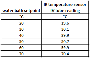
IR temperature sensor readings for six water bath setpoints between 20-60°C are shown in the table below. No sensor reading deviated by more than 0.7°C from the water bath setpoint temperature.
I am still surprised by the accuracy of the results. My first thought was that I may have been too quick to dismiss using a thermistor on the outside of IV tube to get an accurate temperature reading. So I hooked up a couple thermistors I had on hand. The temperature response was at least ten times worse than the IR temperature sensor and the thermistors would only read 47-49°C when the water bath setpoint was 70°C.
It's pretty cool to find that a <$10 part can be used to accurately measure IV fluid temperature through an IV tube. This was not a problem that I thought I would be able to solve at the beginning of this project.
This will likely be the last log of the OpenFluidWarmer project. I had a lot of fun pushing the boundaries of open-source medical device development and developing a working IV fluid warmer prototype. A big thanks to everyone who provided feedback and encouragement on this project over the last six months. Please feel free to message me if you have any interest in the continued development of the OpenFluidWarmer or want to chat about the challenges of open-source IV fluid warming.
-
Measure IV Fluid Temperature with an IR Sensor
11/18/2020 at 05:48 • 0 commentsA low-cost method for measuring the temperature of IV fluids through IV tubing or IV bags would be a game changer for the safety of the OpenFluidWarmer design. I have purchased three GY-906 BAA IR temperature sensors this week for testing. I am encouraged by medical temperature measurement studies that have shown that non-contact IR temperature sensors can achieve +/- 0.5°C measurement accuracy.
Temperature sense of the IV fluid at the IV bag will ensure that the operator has a double check on inlet IV fluid temperature. Inlet temperature determines the length of IV tubing that is to be immersed in the water bath, water bath set point temperature, and IV fluid flow rate.
Temperature sense of the IV fluid in the IV tube at the outlet of the OpenFluidWarmer will ensure that IV fluid is not warmed above the threshold at which hemolysis begins to occur. Warming the fluid above temperature can be caused by immersing too much length of IV tubing in the temperature bath, using too high of a water bath setpoint temperature, assuming too high of an inlet IV fluid temperature, or using too low of a IV fluid flow rate.
Without IV fluid temperature measurement at the inlet and outlet, the burden is on operator to ensure that the IV fluid remains within the normal operating temperature limits. Incorporating IV fluid temperature sense can help reduce the burden on the operator and help quickly identify over temperature hazardous conditions.
I remain skeptical that there might be an accurate, low-cost method to measure IV fluid temperatures through IV tubing and IV bags, but am confident that there is something to be learned from testing these GY-906 BAA IR temperature sensors.
-
Gen 2 Prototype Cost Analysis
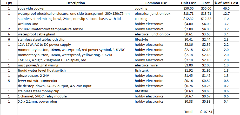
11/10/2020 at 05:03 • 0 commentsThe latest cost workup puts the OpenFluidWarmer Gen 2 design just under $110; roughly $10 above the $100 cost target. It is important to note that these costs include shipping and are based on shipping to the United States. In the table above, items are listed from top to bottom in decreasing contribution to the total cost of the device. The sous vide cooker, electronics enclosure, and stainless steel mixing bowl being the top three most expensive components and representing over 70% of the total cost.
During requirement development I had little visibility on all the required safety features and how much each would cost. At the time, the $100 cost target was my best guess at a competitive upper limit. Since performing the hazard analysis, I have more insight into which safety features are important and which cost increases are well justified for risk mitigation.
I am proposing that the new competitive cost target be moved to $125. This new cost target considers safety features that have not yet been added and an approximation of the price fluctuations that I have observed on the components over the last few months. Even at $125, the OpenFluidWarmer device is at most 22% the cost of a commercially available IV fluid warmer with comparable safety and performance.
I predict that an additional $5-6 of savings is possible with more creative ways of repurposing other common-off-the-shelf items. These savings are just difficult to arrive at quickly. I most often find these opportunities for savings when looking for parts online for other projects. It is always surprising to me how many specialized items that I am totally unfamiliar with can be considered commonly available. Browse AliExpress for ten minutes and you will get an idea of what I am talking about.
-
Operating Procedure and Operational Parameters Table
10/31/2020 at 22:12 • 0 commentsThe operating procedure has had the single most influence on the design of the Gen 2 prototype. The reason for this is simple - the most unpredictable and difficult to control component of the OpenFluidWamer solution is the human operator. Understanding how relays, 7 segment displays, button switches, temperature switches etc. can fail and cause a hazardous condition is a trivial task compared to understanding all the ways the human operator can make an incorrect action that results in harm to the themselves or the patient. Therefore, it has been a major focus of the OpenFluidWarmer design to reduce the number of opportunities that the device can be used incorrectly by the operator and cause a hazardous condition.
See "OpenFluidWamer_OperatingProcedure" in the files section of this project for the latest version of the OpenFluidWamer operating procedure.
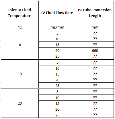
The first step of the operating procedure is to determine which operational parameters to use during device operation. The current approach is to have the operator use lookup tables in the user manual (or perhaps on a laminated sheet attached to the device) to determine the appropriate operational parameters. The images that follow are the proposed format for these lookup tables.
You may notice that there is currently only one entry in the IV Tube Immersion Length column. This one entry represents the only test conditions that the Gen 2 prototype has been tested to so far. It also represents one of the most challenging thermal performance test cases. Consequently, almost all other test conditions in the table will require that a shorter length of IV tubing be immersed to achieve the 38°C outlet temperature at the 70°C water bath temperature. All the "??" entries represent tests that will be performed in the coming weeks to complete the table.
It is also important to note that the current approach uses a constant water bath temperature of 70°C. If the operator needs to change the IV fluid flow rate, the two ways to implement this change with the device is to either change the water set point temperature or change the length of immersed IV tubing. It is less convenient for the operator to change the water bath set point because of how long it will take the sous vide cooker to bring the water bath to the new set point. Instead, changing the length of immersed IV tubing can be done much quicker and will result in an immediate correction to how much heat is being transferred to the IV fluid.
-
OpenFluidWarmer Gen 2 Prototype
10/27/2020 at 15:11 • 0 comments![]()
![]()
![]()
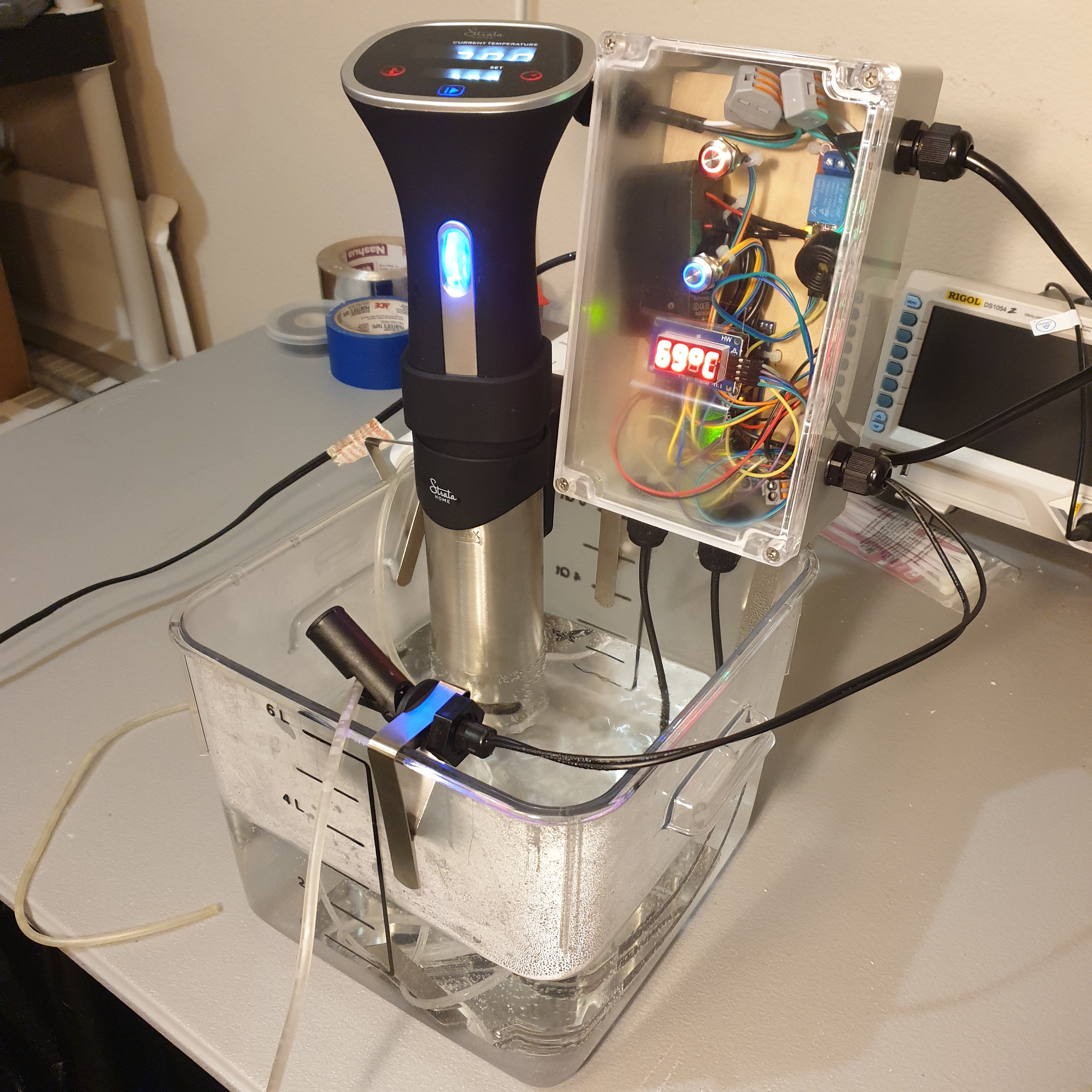
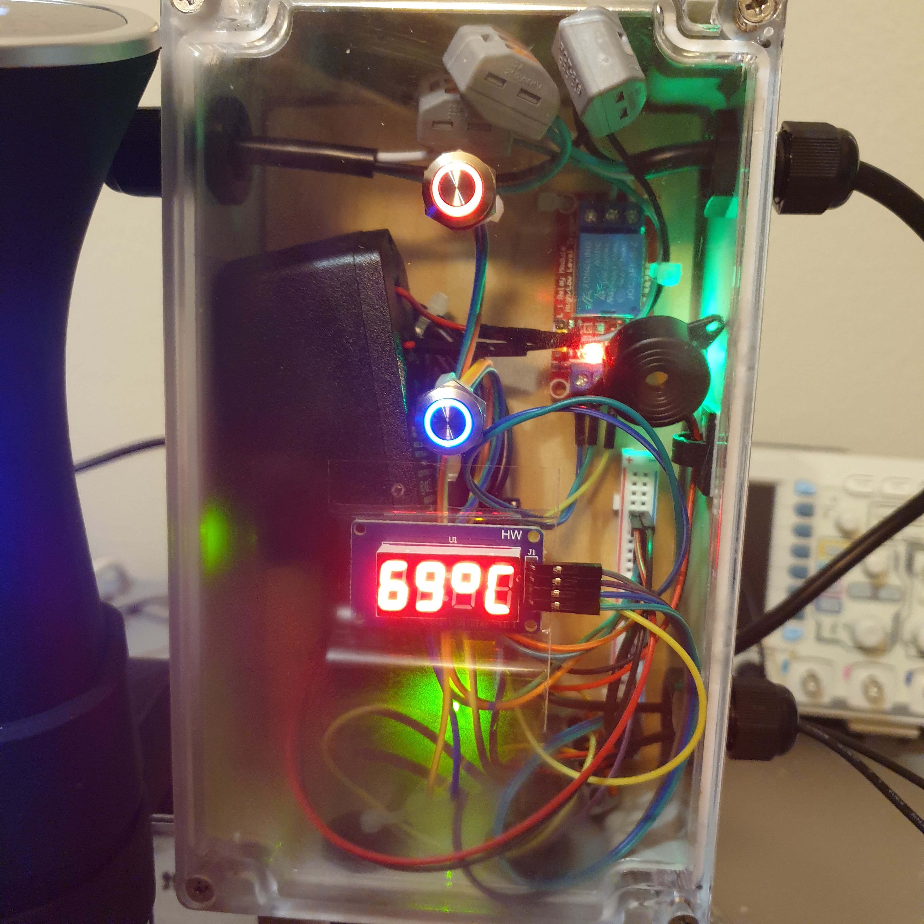
After about two and a half weeks of system design and component selections, it was very fun to finally see this second generation come together over the last four days. I started with writing the microcontroller prototype code. Then tested that code with the benchtop prototype and made corrections as needed. Once I was confident in the code, it took only a couple of hours to decide how to arrange the electronic components in the enclosure and put everything together.
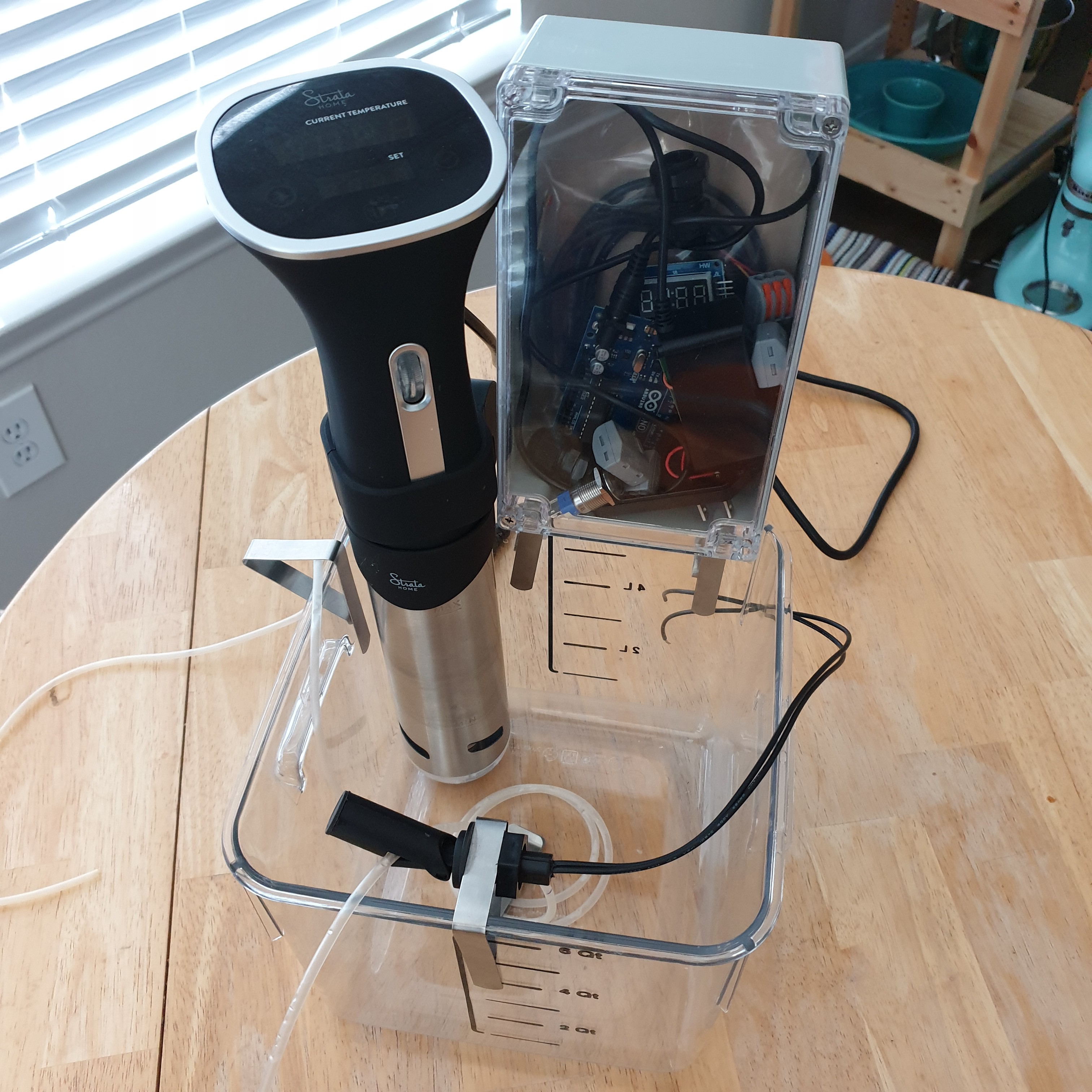
I intend to cover the details of the operating procedure and how the device works in later project logs, but I think it makes sense to provide a high level overview here. The second generation OpenFluidWarmer uses a commercially available sous vide cooker to warm and maintain the temperature of a water bath. While the IV fluid is being administered, the operator immerses a length of IV tubing in the water bath. Heat from the water bath will warm the IV fluid as it flows through the length of IV tubing that is immersed in the water bath. The custom electronics assembly can be thought of as a "safety companion" for the sous vide cooker. It includes safety protections like redundant temperature monitoring, a sous vide cooker power disconnect, and fault detection and alerts.
The next step is to develop and perform several tests to ensure that the device operates as intended.
-
Benchtop Prototype and Operating Logic
10/21/2020 at 04:58 • 0 comments![]()
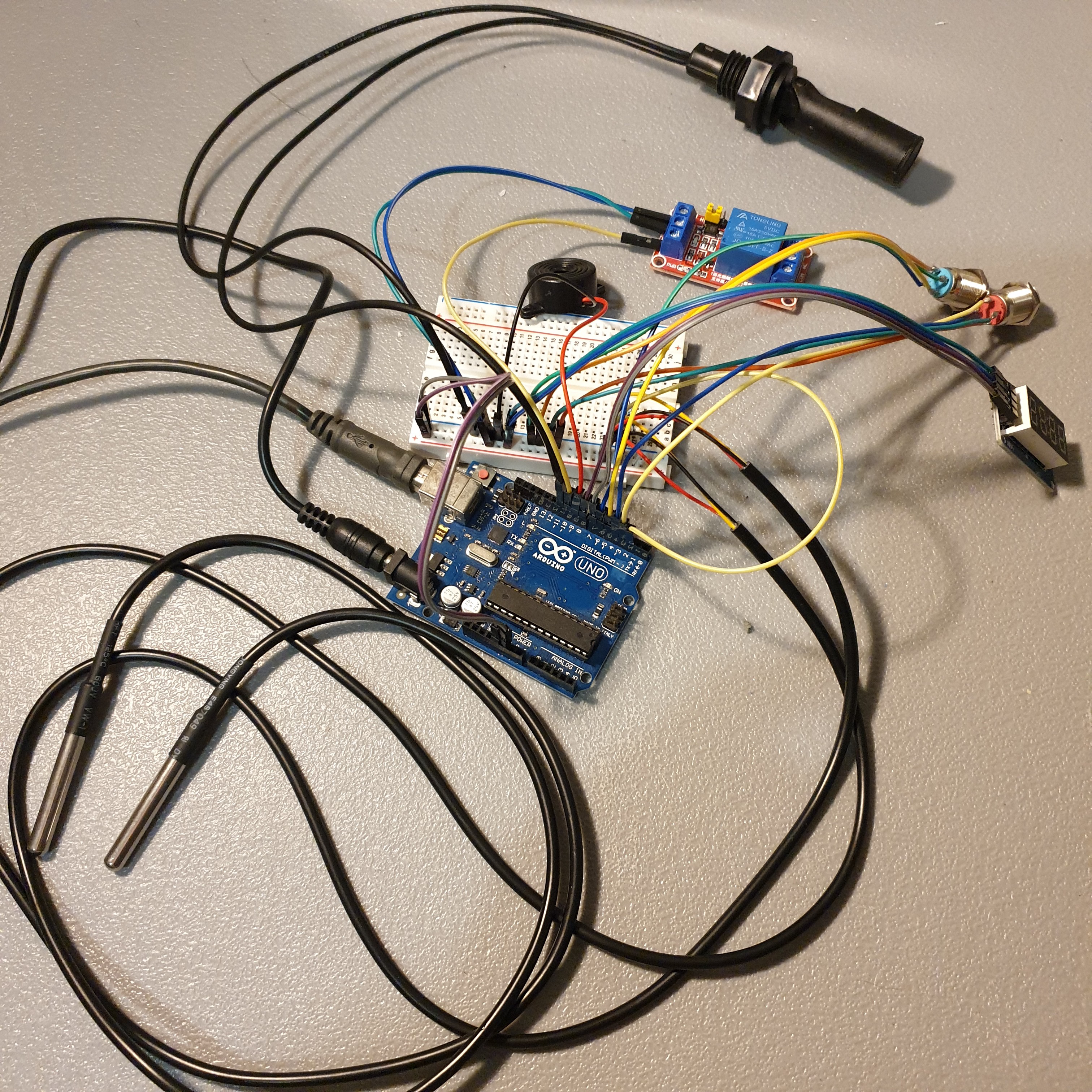
I assembled the benchtop prototype yesterday in about 20 minutes. I will be using it to test the Arduino code in the coming week.
![]()
All-in-all, the signals are very simple. Most of the microcontroller inputs and outputs only have two states - "on" or "off". Even for the 4 digit, 7 segment display and the water bath temperature sensors, there are existing code libraries that make controlling or reading from the components easy.
Five microcontroller inputs:
- two water bath temperature sensors
- sous vide cooker power momentary push button
- set point monitor momentary push button
- IV tube switch
Five microcontroller outputs:
- sous vide cooker power button red LED ring
- set point monitor button blue LED ring
- 4 digit, 7 segment display
- buzzer
- sous vide cooker power relay
The challenging part is developing the logic to enforce a conditional operating sequence. Enforcing which and when controls are available to the operator is a strategy to reduce the cognitive load on the operator as well as to prevent the operator from creating a hazardous condition. Ultimately, this approach is used to ensure the safety of the operator and the patient during device operation.
With the understanding that detailed and easy-to-understand documentation is an important part of open-source design, I have taken the approach of documenting the operating logic in table format. It is something I made up and it does not yet capture all the nuances. I imagine there has to be a better format out there for this type of logic (pseudo code maybe?). Please leave a comment if you have a suggestion.
The table below details the following statement in Boolean logic: "When the device is plugged in, the sous vide power standby and water bath temperature monitor will be activated." The columns represent only the objects that are effected by the control action. The initial conditions must be satisfied in order for the action to be valid. The final conditions are enforced once a valid control action has occurred.
In the example above, the descriptive statement provides more clarity than the table. I find that the opposite quickly becomes true when documenting a control action that is dependent on multiple initial conditions and results in a multitude of final conditions.
It's hard to identify gaps and improve the conditional operating sequence without a good comprehensive format. I know I can just start coding without a solid plan upfront and eventually arrive at the intended operating logic. For the OpenFluidWarmer, the goal is not to just arrive at the intended operating logic but also to justify each line of code and prove that all gaps are closed.
-
Hazard Analysis - risk reduction as-far-as-possible
10/18/2020 at 05:54 • 0 commentsA hazard analysis of the OpenFluidWarmer sous vide cooker design was performed using a reduction as-far-as-possible (AFAP) risk management approach (the latest revision of the hazard analysis is "OpenFluidWarmer_HazardAnalysis" in the project files). The goal of the hazard analysis is to identify the harms and develop the mitigation controls for each significant hazardous condition that can occur during device operation. EN ISO 14971, an ISO standard detailing the application of risk management to medical devices, was used as a reference to perform the analysis.
The OpenFluidWarmer hazard analysis identified six hazards (all with multiple potential causes) and four resulting harms. Many risk controls were identified to further reduce the probability of a hazard condition occurring, but none were identified that would reduce the severity of the harm once a hazard condition does occur.
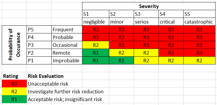
When following the AFAP approach, risk is to be reduced to the R1 rating (per image above) regardless of economic practicality. In cases where it is not possible to reduce risk to a R1 rating, a risk-benefit analysis is to be performed. The risk-benefit analysis must provide evidence (with no consideration given to economic practicality) that the medical benefits of using the device outweigh the residual risks.
The reduction as-far-as-possible risk management approach provides an exciting opportunity to explore the feasibility of electromechanical open-source medical devices like the OpenFluidWarmer. With the number of risk reduction controls required, adherence to AFAP risk reduction presents the most difficult cost challenges for the OpenFluidWarmer design. On the other hand, if it is possible to follow the AFAP risk reduction approach and achieve a low-cost, easy-to-manufacture, component-flexible design, that has huge implications beyond the development of just the OpenFluidWarmer. It means that it may be possible to develop other safe and economically practical open-source medical device designs; some that may even provide more medical benefit to the patient than IV fluid warmers.
-
New Prototype in Development
10/16/2020 at 20:31 • 0 comments![]()
It was decided last week to explore what it would take to develop a safe OpenFluidWarmer design with a sous vide cooker. Testing showed that the constant temperature water bath method with the sous vide cooker was able to meet the thermal performance requirement that the previous two hot plate design could not. Since performance with the sous vide cooker has been so promising, the recent design effort has focused on improving the safety and reliability of the system. The image above is the latest build progress towards the OpenFluidWarmer sous vide cooker prototype.
The most notable design compromise with the sous vide cooker design is the amount of time it takes for the device to warm up and be ready for use. The two hot plate design could warm up in less than 60 seconds from 25°C to 105°C. Whereas the sous vide cooker design takes about 11.5 minutes to warm the water bath from 25°C to the lower required heater set point temperature of 70°C. It is a little misleading to make this comparison because the two hot plate design was never able to meet the thermal performance requirement at the 105°C set point anyways.
At this time, I don't believe a warm up time close to 11.5 minutes to be a significant issue with this warmer. The device could be turned on 10 minutes before the procedure or run continuously during a procedure when need for warming IV fluids was anticipated. Then the IV tubing can be placed into the water bath at a moments notice when warming is needed.
The sous vide cooker design starts to outshine the two hot plate design when it comes to operational redundancies and simplicity of assembly. The sous vide cooker itself includes an independent power button, temperature controller, and temperature display. The additional system housed in the electronics enclosure (what I am calling the sous vide cooker "safety companion") includes button controls, a sous vide cooker power disconnect, temperature monitoring, and state and fault indicator displays. If for whatever reason the sous vide cooker failed, the "safety companion" system will alert the user and potentially disconnect the power. If the "safety companion" failed, it's very possible that the sous vide cooker will continue to operate as intended without issue. Hardware redundancy really helps to ensure safe operation of the device. On top of that, it's very convenient that a full package, cost-optimized constant temperature bath solution like sous vide cookers are readily available for purchase. All you have to do is supply power to it.
Instead, the two hot plate architecture only included one microcontroller/control system and no backups if that failed. Adding redundancies to the two hot plate architecture would greatly increase the complexity of the hardware, software, and assembly.
-
Architecture with Sous Vide Revision 1
10/13/2020 at 04:56 • 0 comments![]()
The first design stage of this project was to find a solution that was capable of the required thermal performance. During this stage the sous vide cooker solution was found. The focus of this next design stage is minimizing the number and severity of operator and patient safety hazards as well as minimizing opportunities for human error in the operating procedure.
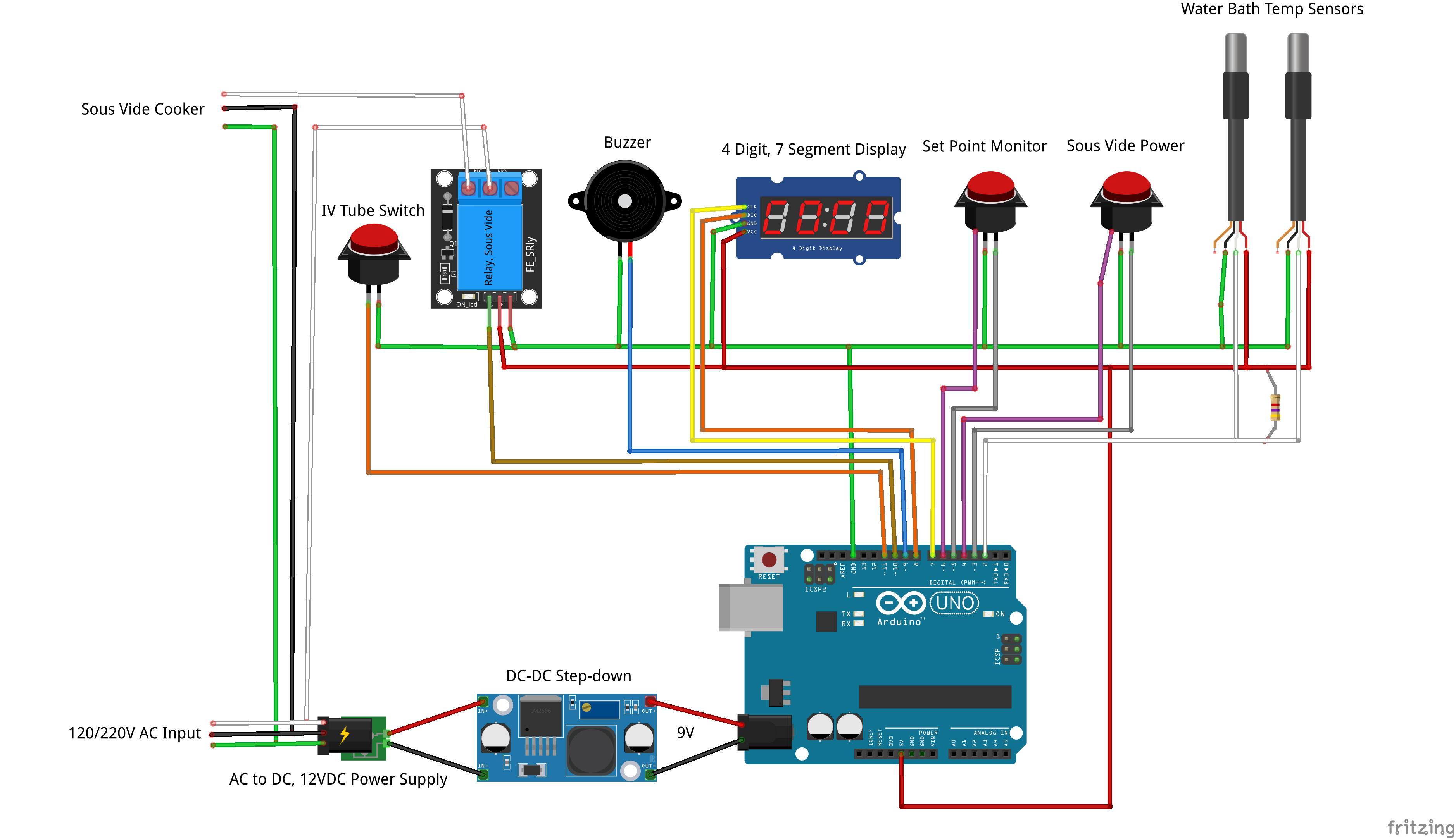
The wiring diagram above depicts the first revisions from this second stage design effort.
The big changes:
- No more toggle switches. Toggle switches are no longer used because they maintain state if the operator unplugs the device. So if the power switch was in the "on" state and the device was unplugged and plugged back in, the safety involved with the operator being able to anticipate and be confident in their ability to control the device state is compromised. Momentary push buttons are used instead.
- Microcontroller is always powered. The microcontroller and associated safety features are always powered whenever the device is plugged in to the AC supply. Ensures that temperature of the water bath is always being monitored and displayed regardless of whether the sous vide device is on or off.
- 4 digit, 7 segment display. During normal operation, the water bath temperature will be displayed. When a fault occurs, the display will transition between the water bath temperature and the number and type of fault that is occurring.
- LED rings on the push buttons instead of independent indicator lights. The "Sous Vide Power" and "Temperature Set" push buttons are the only means to control device state with the microcontroller once the device is plugged in. From a operator perspective, I believe it will be more intuitive that the state indicator lights that change in response to button presses are on the buttons themselves. The "Sous Vide Power" button will use a red ring (implying heater/hot) and the "Temperature Set" button (for setting water bath temperature monitoring) will use a blue ring (implying water bath).
The main design challenge I am working through right now is on how to ensure that the operator submerges the correct length of IV tubing and to ensure that it remains submerged throughout operation.
Most of the electronic components for this new architecture arrive this week. Hope to have a semi-operational assembly by this weekend.
-
New Architecture with Sous Vide
10/09/2020 at 03:25 • 0 comments![]()
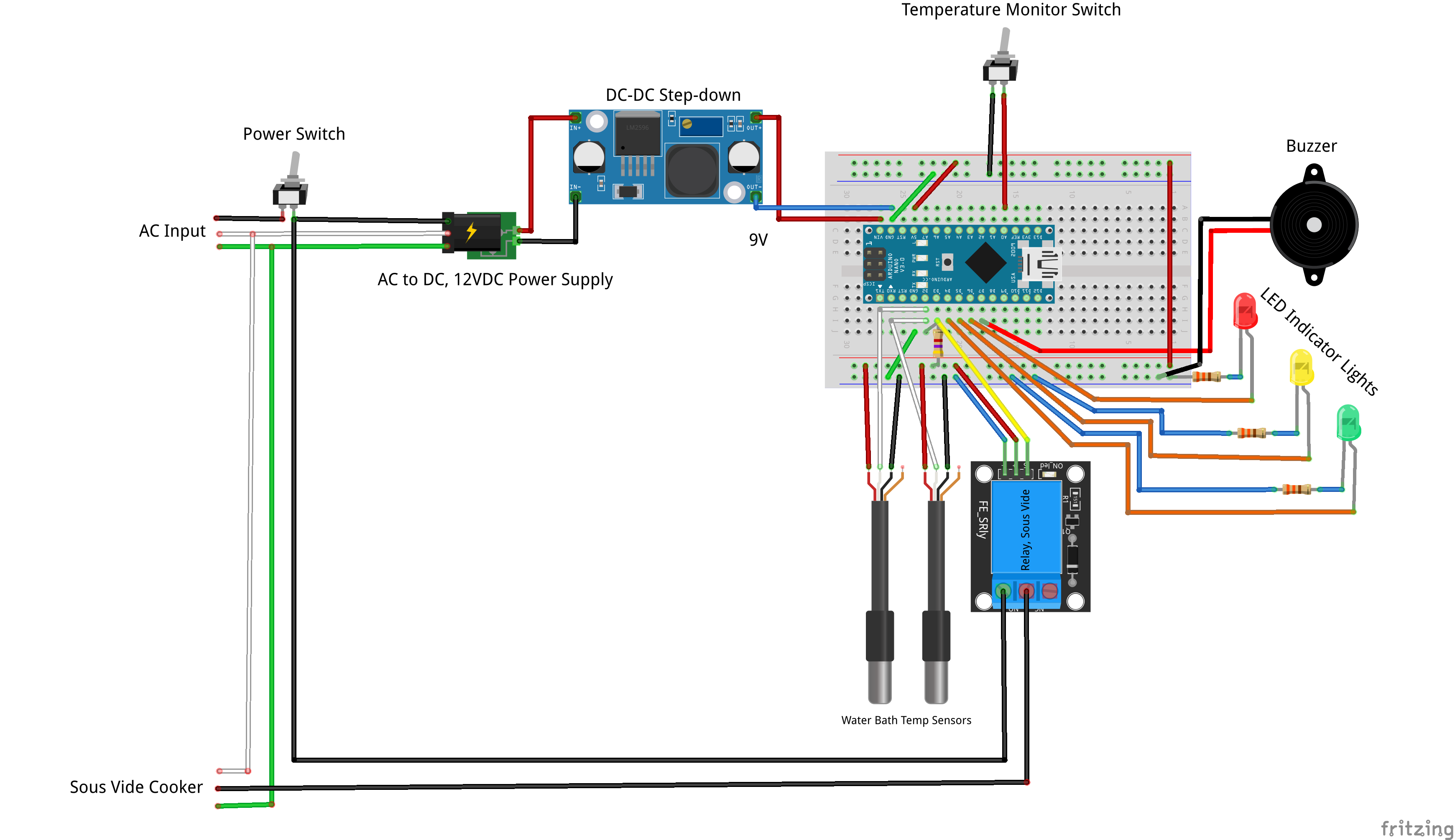
For the new OpenFluidWarmer architecture, the electronics monitor the water bath, alert the user of state and faults, and disconnect the sous vide cooker in the event of a high temperature fault. The new architecture requires fewer electronics components than the previous two hot plate architecture because those components are standard offering in sous vide cookers.
The idea is to package all the electronics in a single enclosure that will be mounted near the sous vide cooker.
Theory of operation is as follows:
- user plugs in the unit into an AC source. If the power switch is in the "off" position, nothing happens. If the power switch is already in the "on" position, see step 2.
- user flips the power switch to the on position. The microcontroller gets powered. If the temperature monitor switch is in the "off" position, the microcontroller commands the relay to close. Closing the relay, provides power to the sous vide cooker. At the same time, the buzzer sounds and yellow LED flashes once a second; indicating that the device is in a warm-up state.
- using the controls on the sous vide cooker, the user sets the temperature and starts the device. Temperature is set based on the IV fluid flow rate. The buzzer sounds and yellow LED flashes once a second; indicating that the device is still in a warm-up state.
- once the sous vide cooker warms the water bath to the temperature set point, the user flips the temperature monitor switch to the "on" position. The buzzer turns off the and the yellow LED stops flashing. The green LED turns on solid; indicating that the device is warmed up and ready to be used. At this point, the microcontroller will be reading the temperature sensors and ensuring that temperatures do not significantly deviate in either direction starting from the moment that the temperature monitor switch was flipped to the "on" position.
- user submerges the appropriate length of IV tubing in the water bath and starts administering the IV fluid/blood product to the patient. If the temperature measured is too far above the set point, the red LED will flash, the buzzer will sound, the relay will open, and sous vide cooker will no longer receive power. If the temperature measured is too far below the set point, the red LED will flash and buzzer will sound. Then it will be up to the medical professional recognize that there is a fault and either turn off the device or allow it to continue operating.
- user removes the IV tubing from the water bath and flips the power switch to the "off" position when finished.
Couple of other thoughts:
- I am thinking of staggering the water bath temperature sensors at different heights in the water bath. Then track the temperature difference between the two sensors. If the temperature difference is too high, that indicates that either the temperature bath is not at a uniform temperature or one of the sensors is out of the water because the water level is too low. At least one water bath temperature sensor should be positioned at either the minimum water level required for the sous vide cooker or minimum water level required to submerge the IV tubing (whichever is greater) to ensure proper water level is maintained.
- After writing about many of the fault scenarios above, it's clear to me now that three colored LEDs is not sufficient to effectively communicate device state and faults to the user. Whatever is considered next needs to have more resolution, but also be able to be clearly read/understood from 1.5m away.
- My intention is to use a Arduino Uno microcontroller instead of the Nano depicted. The 5V pin on the Nano can only supply up to 50mA. Whereas the Uno can supply up to 500mA at the 5V pin. The 5V relay draws about 70mA. I could stay with the Nano if I added another DC-DC step down and tuned it to 5V, but the combined cost of the extra step-down and Nano is more than what I purchase an Uno for. Ideally, I would get rid of the 12V to 9V DC-DC step down. But it is my understanding that the voltage regulator on the Uno can only supply something close to 100mA at 12V input voltage. I had a voltage regulator blow on a Nano recently when powering it at 12V so I am wary of doing that again.
- I wonder how many times the cheap relay module will open under the load of the sous vide cooker during fault conditions.
OpenFluidWarmer
a safe, low-cost IV fluid warmer solution; for when commercially available IV fluid warmers are too expensive or cannot be sourced
 John Opsahl