Supplyframe DesignLab
-
Using Gesture Control for Roku
09/30/2020 at 07:18 • 0 commentsIn the last log, I was experimenting with integrating Roku into our platform, using a ESP32-based "breadboard keyboard" for Roku remote emulation. In this log, I am going to discuss replacing the input control with the IMU-based gesture control prototype. I will also detail the hardware updates made to the gesture control remote, which was just shipped to UCPLA a few days ago!
![]()
Hardware Updates to the Gesture Control Remote
Up until now, the gesture control prototype was the M5StickC microcontroller. The limitations that needed to be addressed were 1) increasing battery life, 2) adding a user-friendly switch, and 3) adding a vibrating motor. These details were discussed in a previous log and developed further here. One change in direction was made from that previous log to this one. Instead of using a reed switch, I decided to stick with a tactile switch for switching device states. After reading more thoroughly about the hazards of rare-earth magnets for devices like pacemakers and hearing aids, it was better to play if on the safe side and make sure nothing we give to the user is dangerous.
Below are some images of the electronic components as well as the 3D printed enclosure (more detailed documentation is being prepared and will be uploaded soon).
![]()
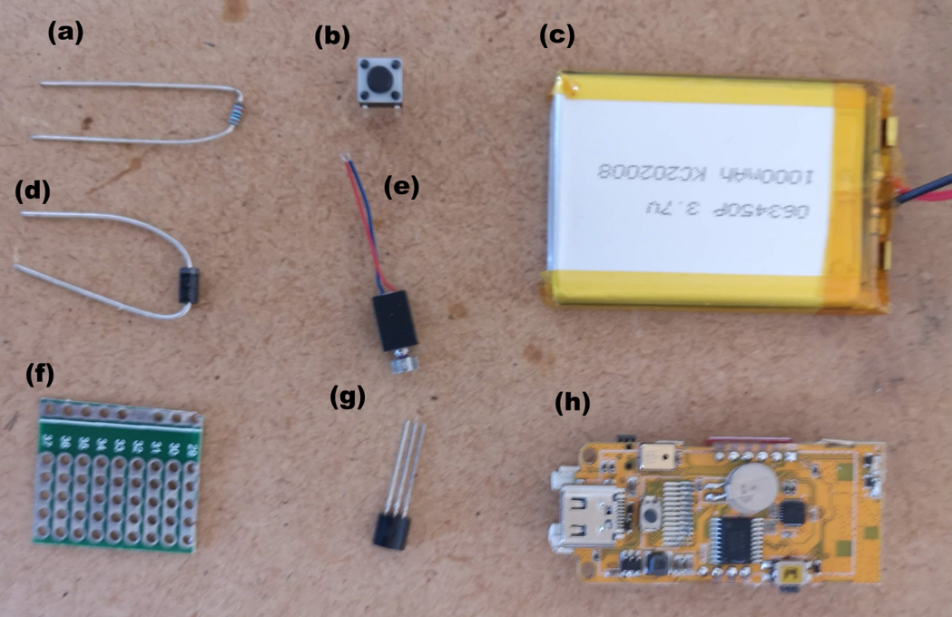
(a) resistor (b) tactile switch (c) 1 Ah Lipo battery (d) diode (e) vibrating motor (f) protoboard (g) MOSFET (h) M5StickC PCB ![]()
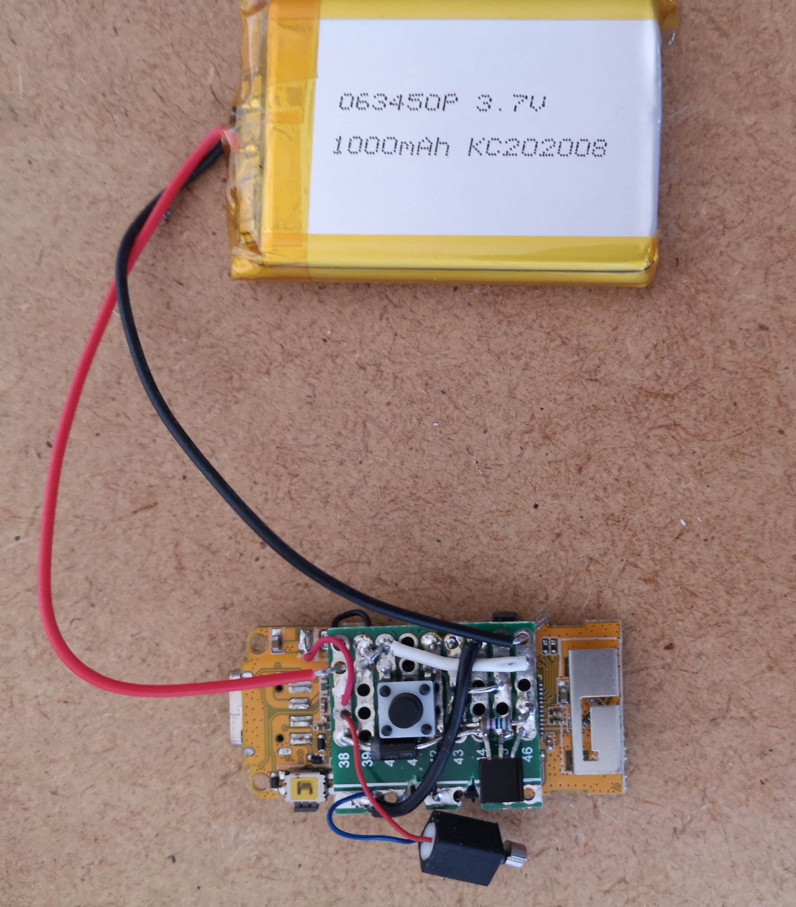
All electronics were soldered to the green protoboard before mounting on the orange M5StickC PCB. The M5StickPCB had a few header pins sticking out from one side that made it easy to mount in a compact space (see previous log). ![]()
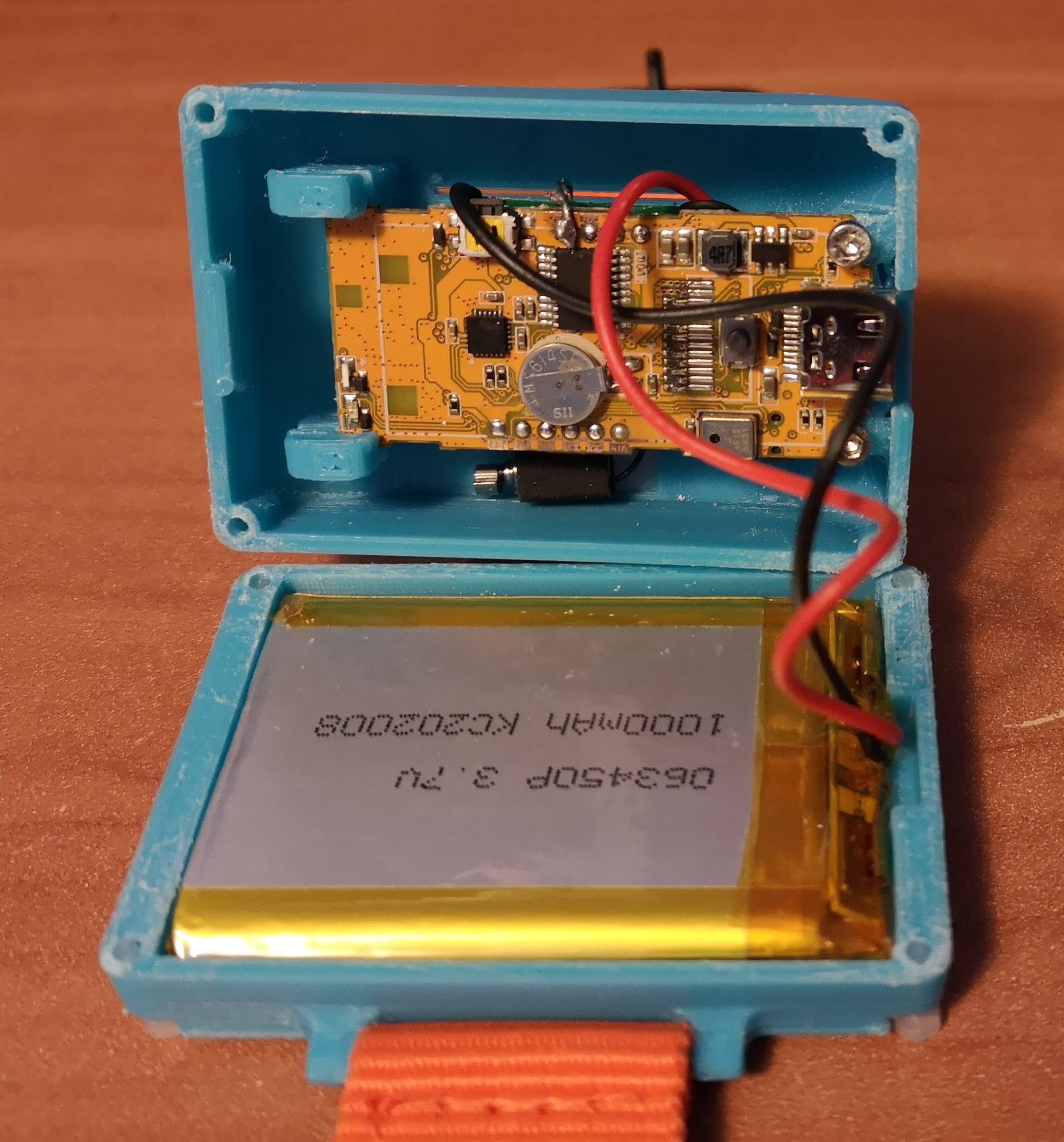
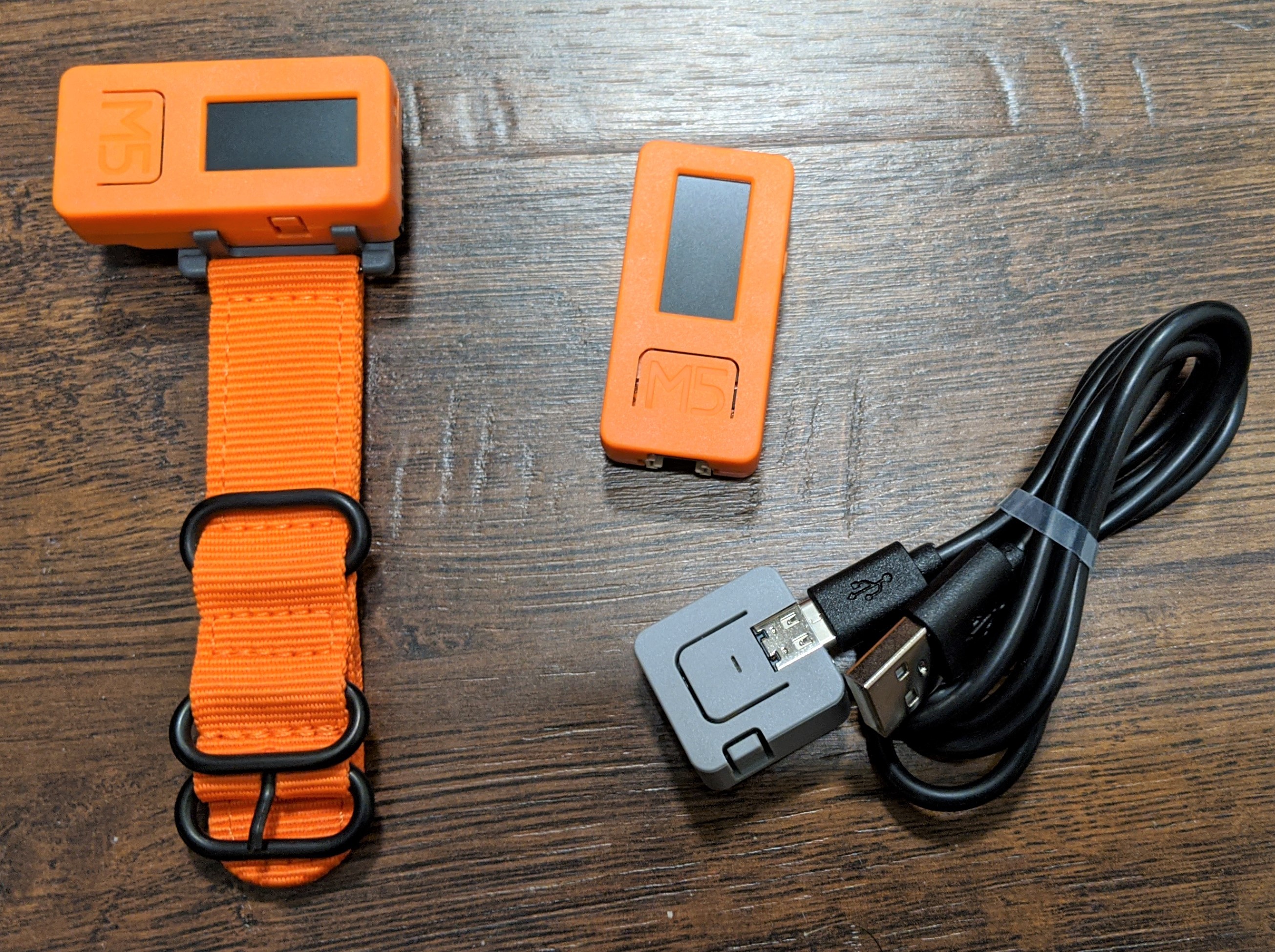
Device interior showing the new PCB mounted within the 3D printed enclosure. ![]()
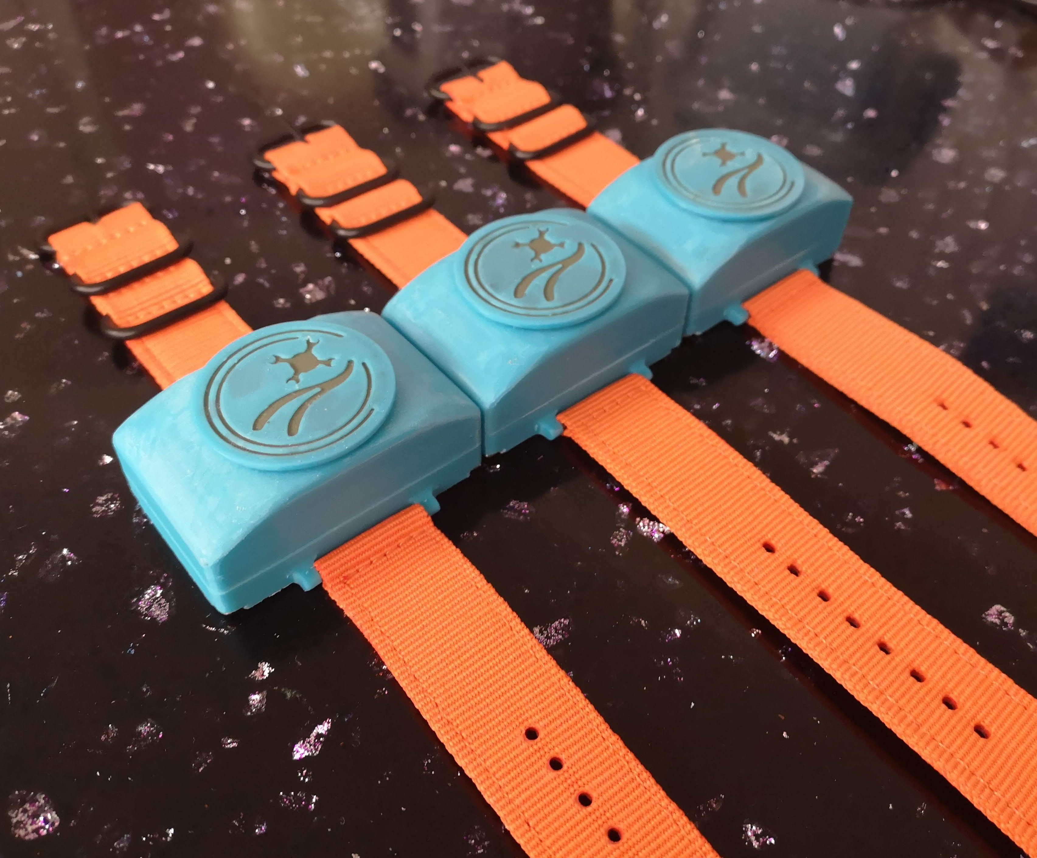
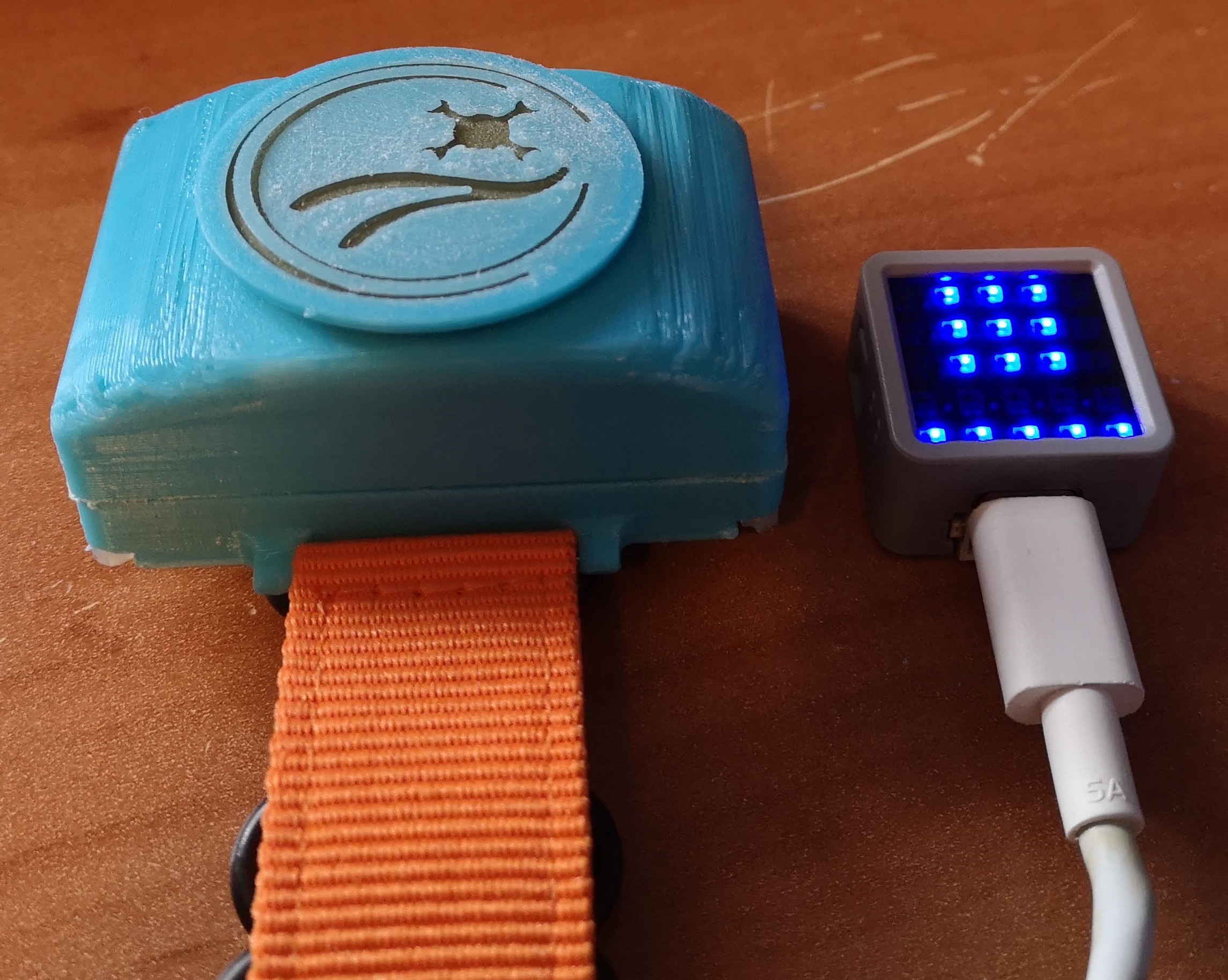
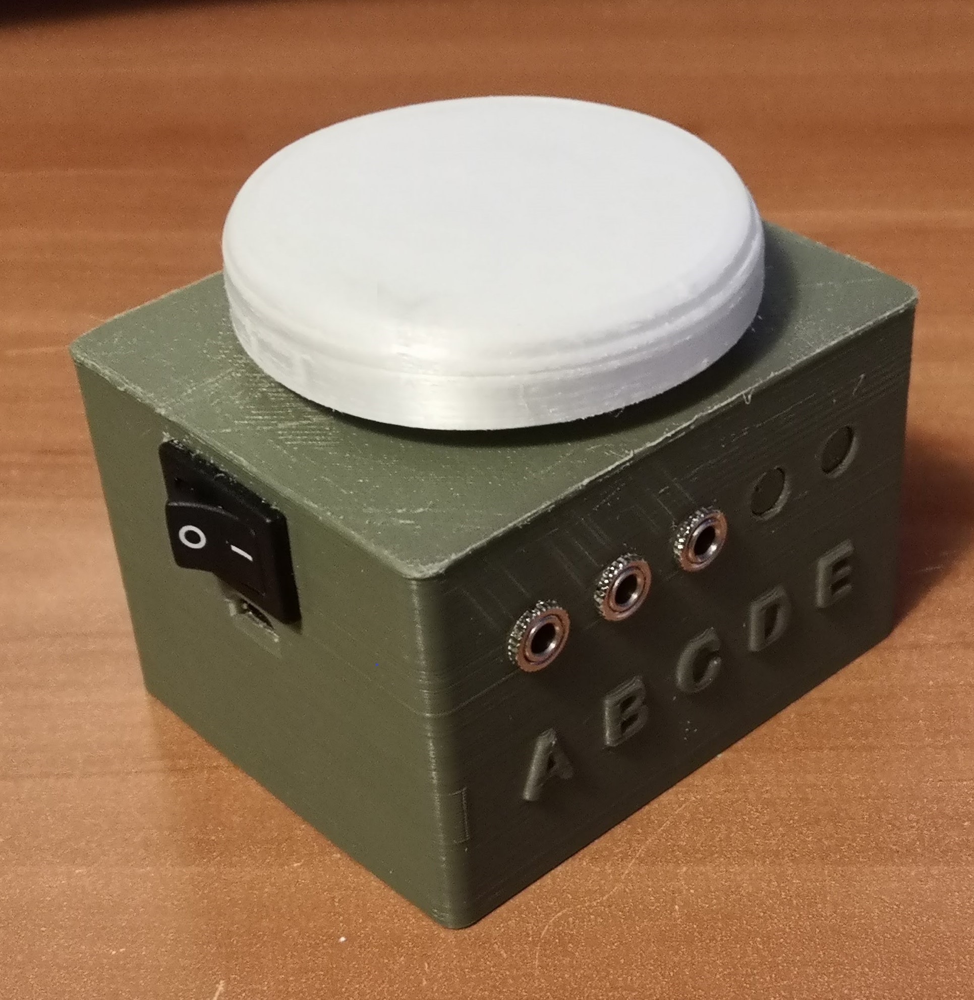
Device exterior showing the large, easy to press button. The device on the right is a "dongle", which has a few purposes. It receives the signals from the gesture remote and processes it before relaying commands to other IoT devices. Second, it is used to calibrate the gesture remote for each user. Third, it displays some information on the small LED screen, including the state of the device (top 3x3 array) and a battery indicator (bottom row). Software Problems: ESP-NOW and MQTT Doesn't Work Simultaneously
While transitioning from the breadboard keyboard to the gesture control remote for using a Roku, I ran into the biggest technical issue faced in this project. With the breadboard keyboard, a button press would publish a MQTT message, which would be received by the Raspberry Pi running Home Assistant. However, when I tried to integrate the gesture remote with MQTT, the ESP-NOW communication between the gesture remote and the dongle stopped working. I spent quite some time debugging this and looking around for answers, but couldn't get it to work. I also tried replacing one of the communication methods with bluetooth or painlessMesh, but wasn't happy with either approach because messages were sometimes missed.
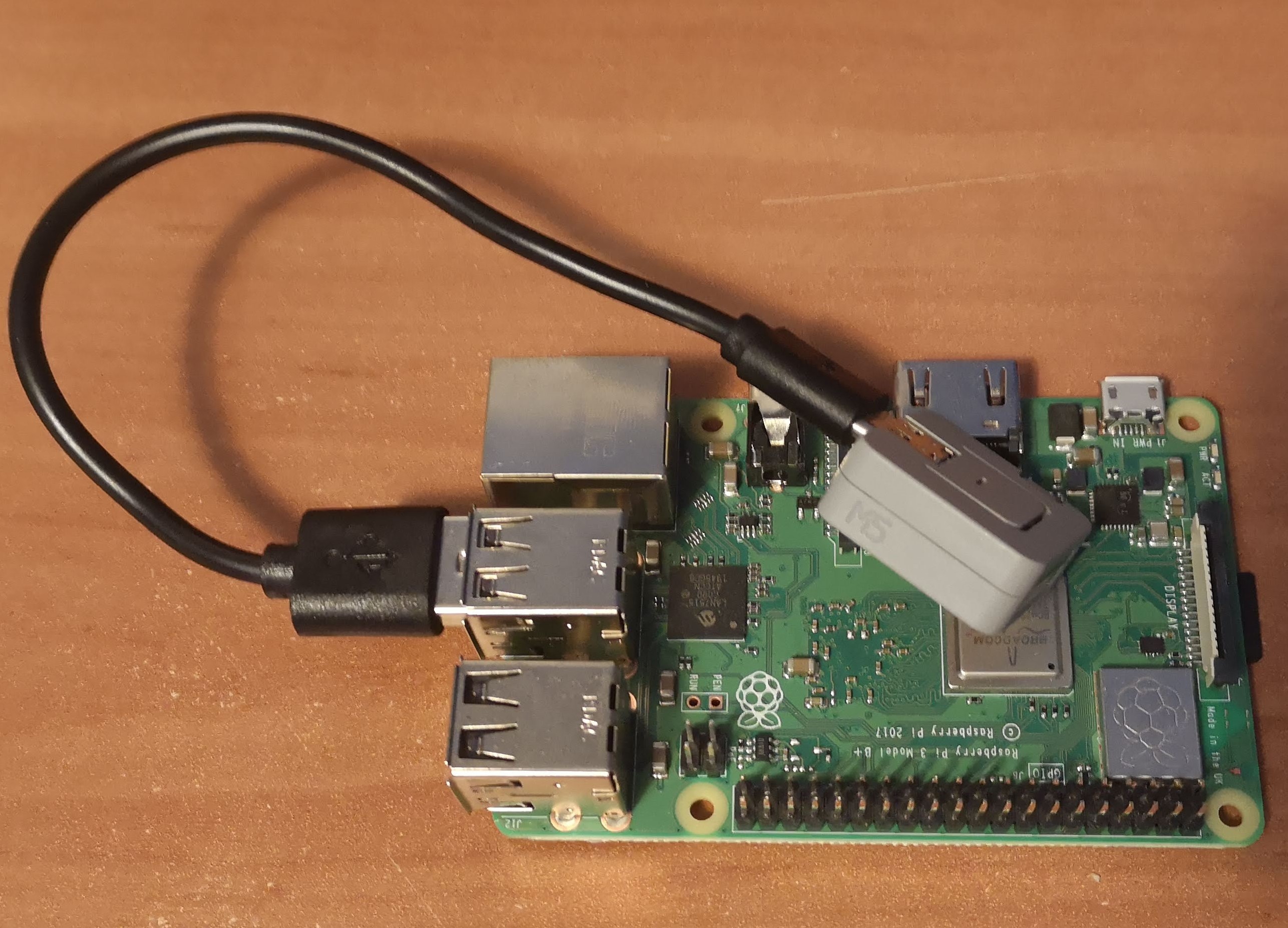
In the end, I settled for a workaround where I have an ESP32-based board plugged into a USB port of the Raspberry Pi. The ESP32 board communicates with the dongle through ESP-NOW, waiting on a message, which is then relayed to the Raspberry Pi through serial communication to trigger a home automation action.
![]()
Raspberry Pi/Home Assistant Hub workaround. Adding an additional ESP32-based board to the platform, physically connected to the Raspberry Pi. This grey device is programmed to receive messages via ESP-NOW from the dongle and sends messages via serial communication to the Raspberry Pi. Looking at this problem again, I think the question comes up: Why is the dongle necessary? Why can't the gesture remote handle the signal processing and directly send MQTT messages to the Raspberry Pi. There were two initial reasons why this was done, and they might not be valid reasons depending on the situation. First, I wanted the gesture remote to be as power efficient as possible and the only task it was supposed to do was sending IMU signals. Second, I wanted to keep the option open to connect the dongle to multiple input devices and combine the signals together before triggering an action for increased functionality. I am not a software person and fully believe there is a better solution than what I have done so far, so this setup needs to be scrutinized further.
Gesture Control for Roku Testing
The keyword in this project is designing something that is "universal", so we want an input device that can be used to control a phone, a computer, and something like a Roku (and a million other things). Previous testing established a Bluetooth connection between the gesture remote and a computer. Because Bluetooth doesn't depend on WiFi and has relatively low latency, I wanted to keep using Bluetooth for using computers/phones/tablets especially when considering a user using something like Photoshop.
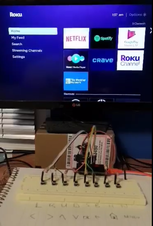
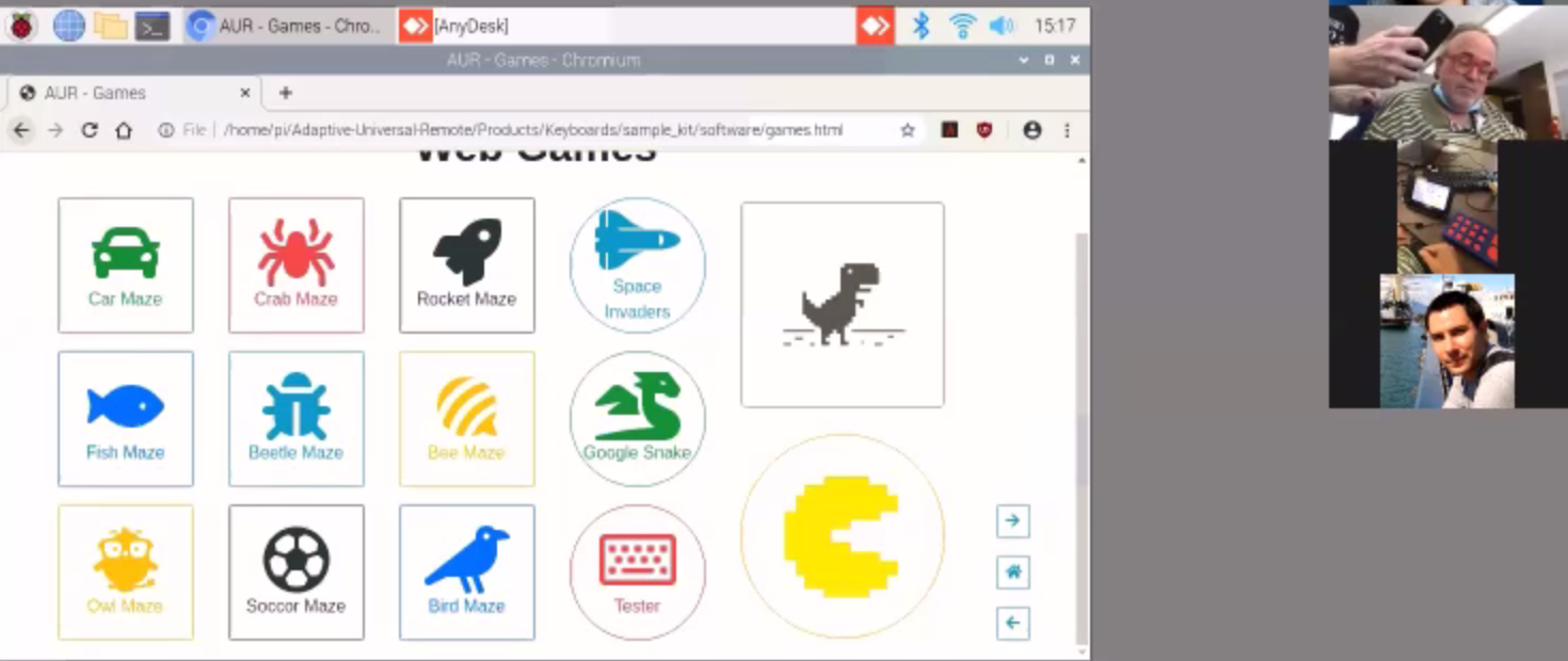
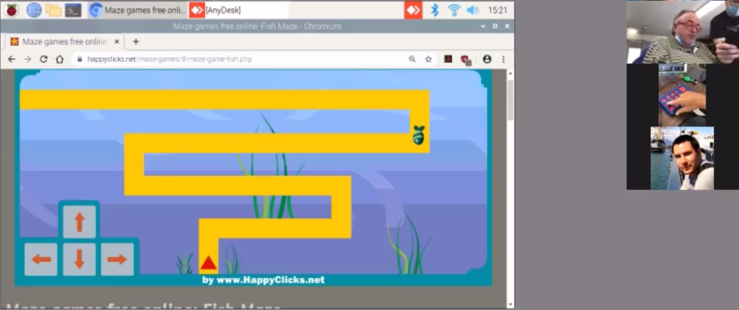
In addition to Bluetooth for a computer, I added the functionality of the Roku control via ESP-NOW to the Raspberry Pi/Home Assistant as described in the previous section. Switching from sending Bluetooth to ESP-NOW was done by pressing the button on the gesture control remote. The video below is a demo of switching from playing a computer maze game to navigating Roku to play a Netflix show and then back to playing the computer maze game.
In this example, we've been able to demonstrate we can press arrow keys on a computer and control a Roku media player. I believe these proof-of-concepts can translate well to other applications. For instance, instead of setting up Home Assistant to use a Roku, there are minimal changes that need to be made in order to use something like Chromecast or other smart devices (which I hope to demonstrate as well). In regards to the computer, the next step is to integrate mouse movement to open up more possibilities. One targeted application is using Photoshop, which would complement the services UCPLA offers to their community.
-
Stepping into the Digital World: Roku Remote Emulation
09/06/2020 at 06:48 • 0 commentsPrevious project developments have heavily focused on physical hardware prototyping of a keyboard and motion-based remote controller. One of the tasks that haven't been explored in depth is the peripheral digital devices that we can control with our prototypes. We have discussed some ways to control a Roku media player as a proof-of-concept starting point and in this log, I will detail one method using an ESP32 microcontroller through Home Assistant to emulate a Roku remote.
![]()
Simple ESP32 Keyboard
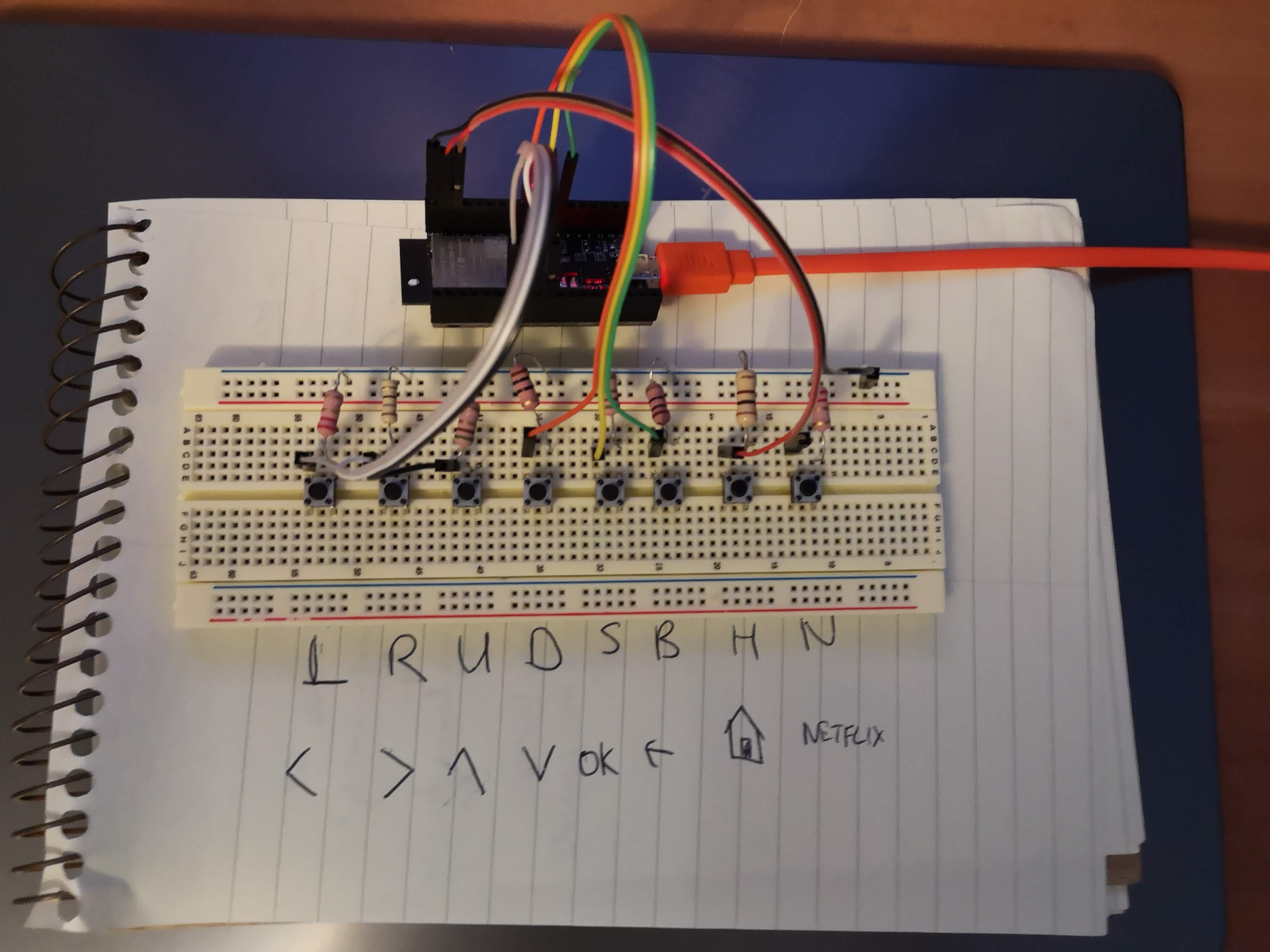
While we are working on a more developed keyboard prototype, I created a low-fidelity one for the purposes of debugging. This is shown below. It is 8 tactile switches connected to an input pin on the controller. The uploaded sketch publishes a message (UP, DOWN, HOME, etc.) to an MQTT broker, which will be used as a trigger to perform an action on the Roku.
![]()
Home Assistant on a Raspberry Pi
There are many possibilities on how we can communicate from a microcontroller to the Roku. I chose to use Home Assistant because it was simple to setup, easy to learn, and has integrations with the majority of smart devices. This last point is important because it makes it easy to translate from controlling a Roku to controlling another device like an Amazon Echo or Google Nest.
Setup Procedure
The setup to install Home Assistant on a Raspberry Pi was followed from the Home Assistant website. After, the Roku and MQTT broker integrations were setup for this specific example.
![]()
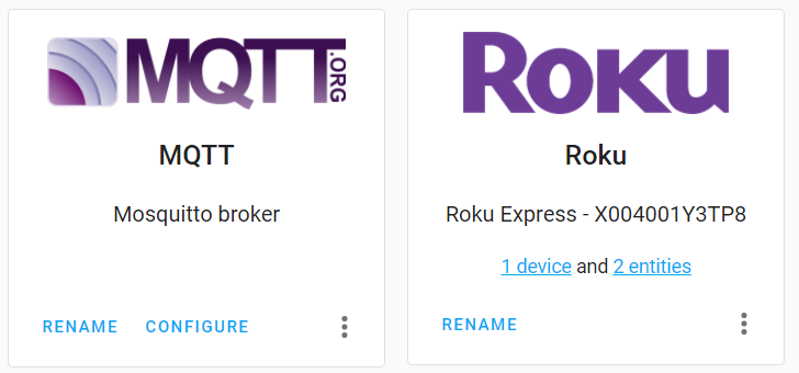
Roku and Mosquito MQTT broker integrations configured, shown on the Home Assistant dashboard. The next step was to establish a connection between Home Assistant to the Roku media player. Tests scripts were written where a button on the Home Assistant dashboard could be used to send Roku commands.
![]()
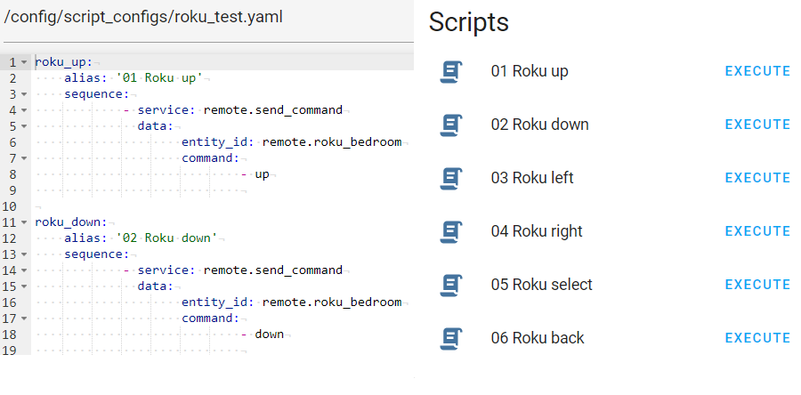
Left: Two sample scripts shown of up and down roku commands. Right: Script execution buttons on Home Assistant dashboard. Once that was done, the ESP32 microcontroller needed to send messages to Home Assistant. With the MQTT broker configured, short messages were published to HA, which could be seen from the Home Assistant dashboard.
![]()
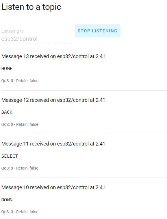
Screenshot from Home Assistant Dashboard MQTT broker configuration page. Waiting for button presses on the ESP32 controller, and receives messages (HOME, BACK, SELECT, DOWN). Finally, an automation routine was written to combine the trigger from the microcontroller and to perform actions on the Roku media player. Two simple automation scripts are shown below.
![]()
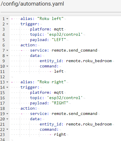
Two automation scripts shown. First script waits for the message, LEFT, to trigger the action of pressing the left button on the Roku. The video below shows the ability to use the 8 buttons to emulate Roku remote to control a Roku media player.
-
Upgrading Hardware of IMU Motion Sensing Remote
08/26/2020 at 08:32 • 0 commentsCurrently, we've been using the M5StickC platform out of the box as our first iteration of our IMU-based motion sensing remote. At its price point of 10 dollars, it included a lot of components in a small package, great for wearable device development. Below, I summarized a table of the different features of the M5StickC, highlighting the useful components for an IMU remote.
FEATURE USEFUL? NOTES ESP32-PICO YES low-power microcontroller 6-AXIS IMU (MPU-6886) YES main feature of this universal remote Real Time Clock (RTC) module (BM8563) YES Important for deep sleep functionality of ESP32 chip Power Management Unit (PMU) (AXP192) YES 3 TACTILE SWITCHES MAYBE Difficult for the user to press these buttons IR LED PROBABLY NOT RED LED MAYBE Can be used as an indicator light (i.e. low battery) HEADER PINS MAYBE modularity, add more things custom for each user MICROPHONE NO LED DISPLAY (0.96") NO small display not suited for this population, high power consumption LIPO BATTERY (85 mAh) YES/NO Battery capacity needs to be increased to be useful The first prototype was helpful in gaining useful insight for our first user testing session. The second iteration will include some additional features to address making the device wireless by having a larger battery, incorporate haptic feedback, and adding a non-contact button for turning the device on/off.
INTEGRATING NEW FEATURES
My initial thought was to use the header pins and attach a second housing to the orignal M5StickC platform, which is seen from some of the hats from their website. With this approach, I tried to imagine what the updated device would look like and could not envision a compact design. I also didn't like the lack of robustness of using the header pins for connecting the additional features.
My next idea was to open up the device and see what the guts looked like. I ended up breaking some parts including the LED display and one of the PCBs. Regardless, there's a picture of the main PCB below.
![]()
M5Stick PCB. On the topside, we see the small battery connections as well as 10 header pins to a second red PCB for external connections (top left box). I had to break this PCB in order to detach it from the original housing. On the backside of the PCB, there are some more components such as the LED display and the IR/red LEDs. This main PCB had all the main components except including the battery connection and decided to just mount a second board with all my additional features onto the header pins, similar to how the red PCB was attached. This implementation will be shown at the bottom of this log.
LARGER BATTERY FOR PRACTICAL APPLICATIONS
The current 85 mAh battery allowed a runtime of about 20 minutes, not really useful for any applications. Thus, for our first prototype that we shipped out, we instructed our users to keep the device plugged in to a wall/computer.
I measured the current consumption of just sending IMU signals to a receiver to be about 120 mA. I hooked up a 400 mAh battery to the M5StickC and got just over 3 hours of runtime, which correlated to the current measurement. When I set the device to deep sleep mode, it drew about 10 mA, which is higher than the 10 uA of current draw in deep sleep mode of the ESP32 development board. This is something I still need to look into. I also measured the current while the device was turned off and was surprised to find it drew about 7 mA of current. After looking at some online forums, it seems like this wasn't a mistake and is a bug of the platform. For this application where I'm not requiring a device to run for months or years, I think the current consumption at off/deep sleep states are good enough for now.
I ended up choosing a 1,000 mAh battery which would extrapolate to about 8 hours of runtime of just sending IMU signals. However, considering I want to power a vibration motor and maybe other features, the runtime would probably reduce by an hour or two. This battery has dimensions of 50 x 32 x 5 mm and weighs 24 grams. It is both the largest and heaviest of the electronic components, which will strongly influence the housing size.
VIBRATING MOTOR FOR HAPTIC FEEDBACK
For users who have difficulty with line of sight, having a solution that solely relies on visual feedback isn't ideal. Many of these users can sense touch, so it makes sense to include some vibrations similar to our phones. I tested two different vibrating motors and didn't really feel a difference in vibrations or see a significant different in current consumption or size. Currently, I am planning to use this one. There are still unanswered questions regarding UX, such as when to send pulses and the types of pulses (two short pulses, one long, etc.) that makes the most sense in different scenarios.
REED SWITCH FOR STATE SWITCHING
The current method for changing states from on and off is by using a small tactile switch on the side of the M5StickC device. It is way too small for a user with cerebral palsy to use this switch as even I have difficulties pressing this button. This functionality of switching from active state to sleep state is critical for extending battery life and device runtime and needs to be able to be done by the user.
The easiest option is to integrate a large button, such as the one from our keyboard input device or the one button device. This option is not being ruled out, and I would consider it the fallback option. An alternative would be to use the tactile switches on the PCB and make a larger button that's easier to press. However, this would increase the size of wearable device and makes the design more clunky.
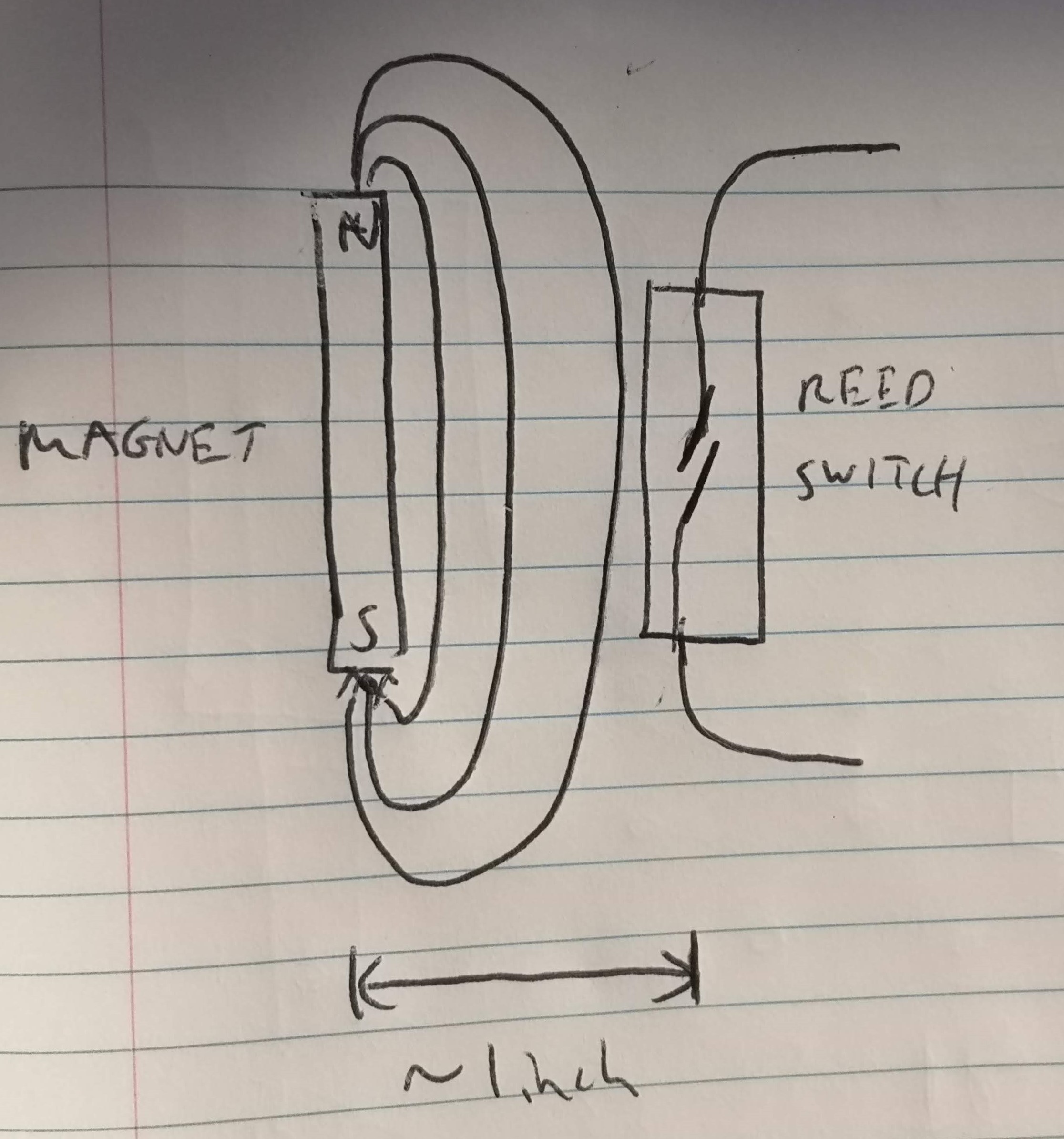
The direction I'm leaning towards is to have a reed switch attached to the IMU device, which gets activated near a magnet. From initial testing with a weaker rod rare-earth magnet, I was pretty satisfied with the activation range with the weaker magnet, and could turn the switch on from about 1 inch away. The ideal alignment of the reed switch and magnet is shown in the picture below, but even if it wasn't perfectly aligned, it still worked at a certain distance.
![]()
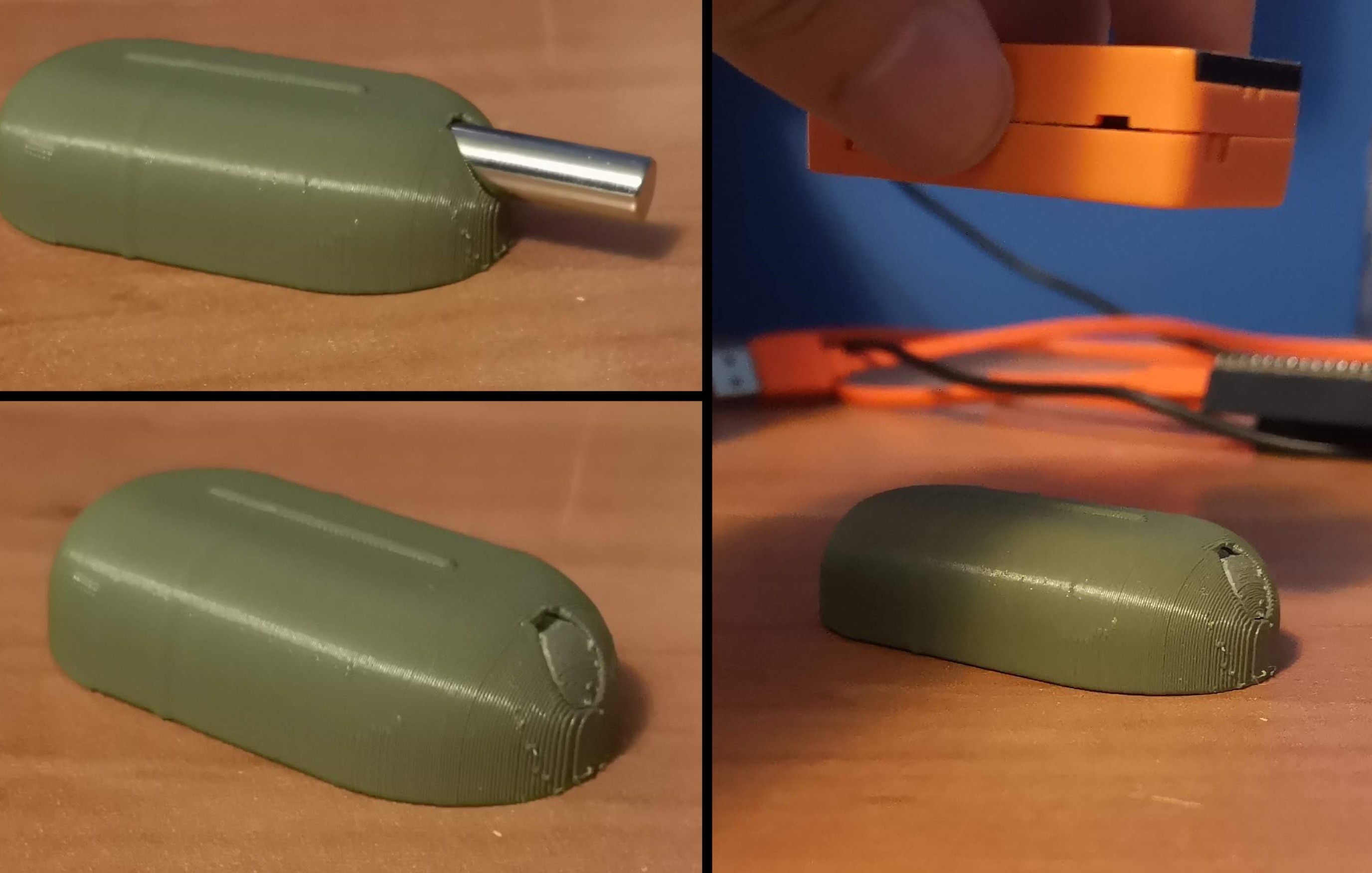
I bought a larger, stronger magnet and wanted to test the increased range, but ended up breaking the reed switch before I could :'(. The plan is to encase the magnet inside a housing (there's a safety issue with using strong magnets so having some separation distance can be beneficial here) that can be mounted to a wheelchair or desk near the user at all times. Another test to find the activation range of the switch will be done before finalizing the device. Below are images of the first prototype of the magnet housing.
![]()
Top left: 3D-printed housing with hole for magnet (1/4" diameter, 1" long). Bottom left: magnet encased in housing. Right: Device and magnet need to be somewhat aligned. Doesn't need to be perfect, can be off to the side or rotated by a bit. Exact range to be determined. PUTTING IT ALL TOGETHER
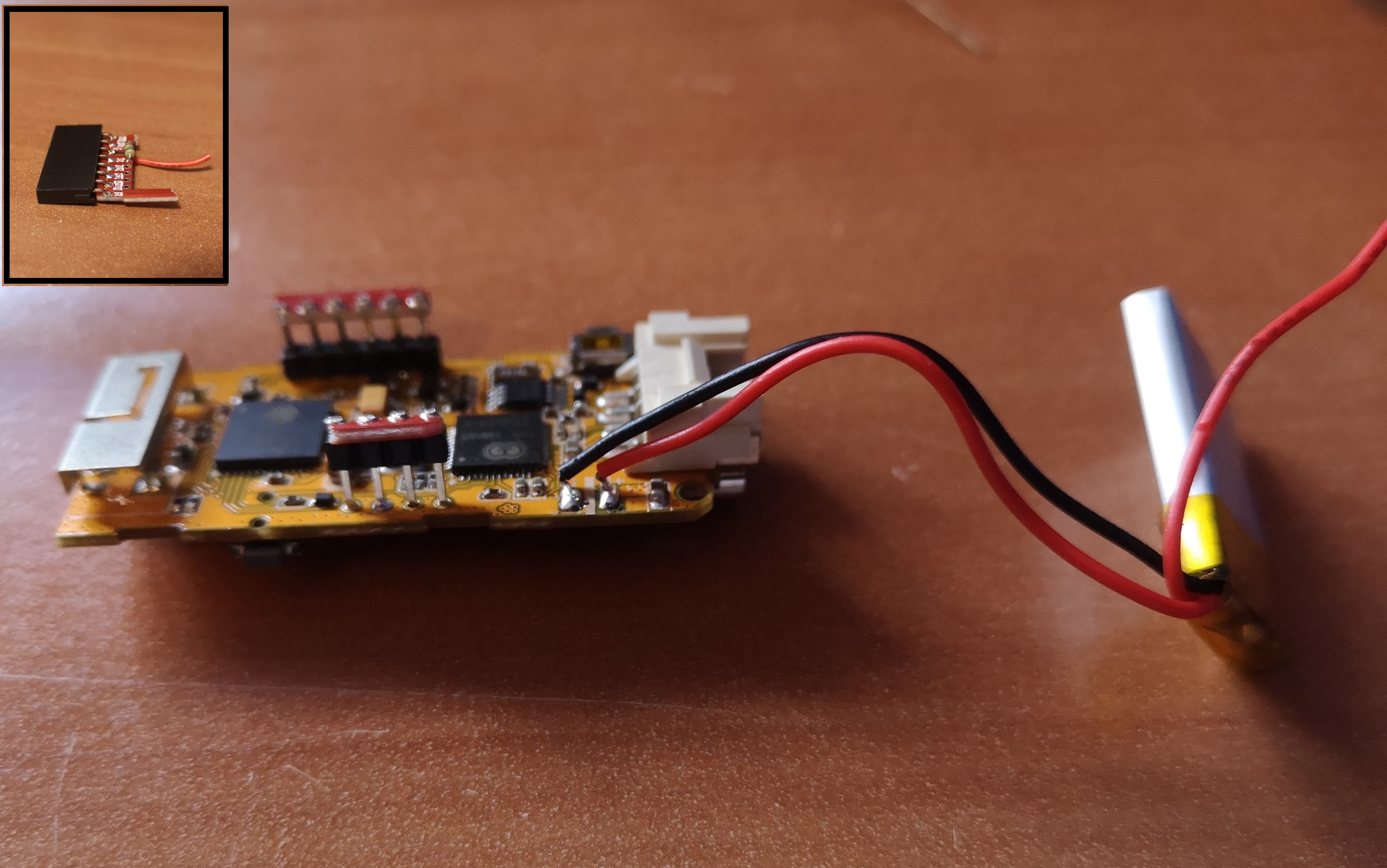
For integrating the battery, I snipped off the two wires connecting the existing 85 mAh battery and replaced it with a larger 400 mAh battery, which is a substitute for the 1000 mAh battery for the final iteration. I didn't see any issues with doing this and was able to charge the 400 mAh battery through the USB-C port. Initially, I was going to use an external battery charger board, which would have been an extra component for this device. By replacing the battery in this fashion, I can utilize the on-chip LDO voltage regulator and save some space. The other change was to increase the charging current, proportional to the increase in battery capacity. I intend for the final charge current to be about 500 mA, meaning it will take 2 hours for a full battery charge for a 1000 mAh battery.
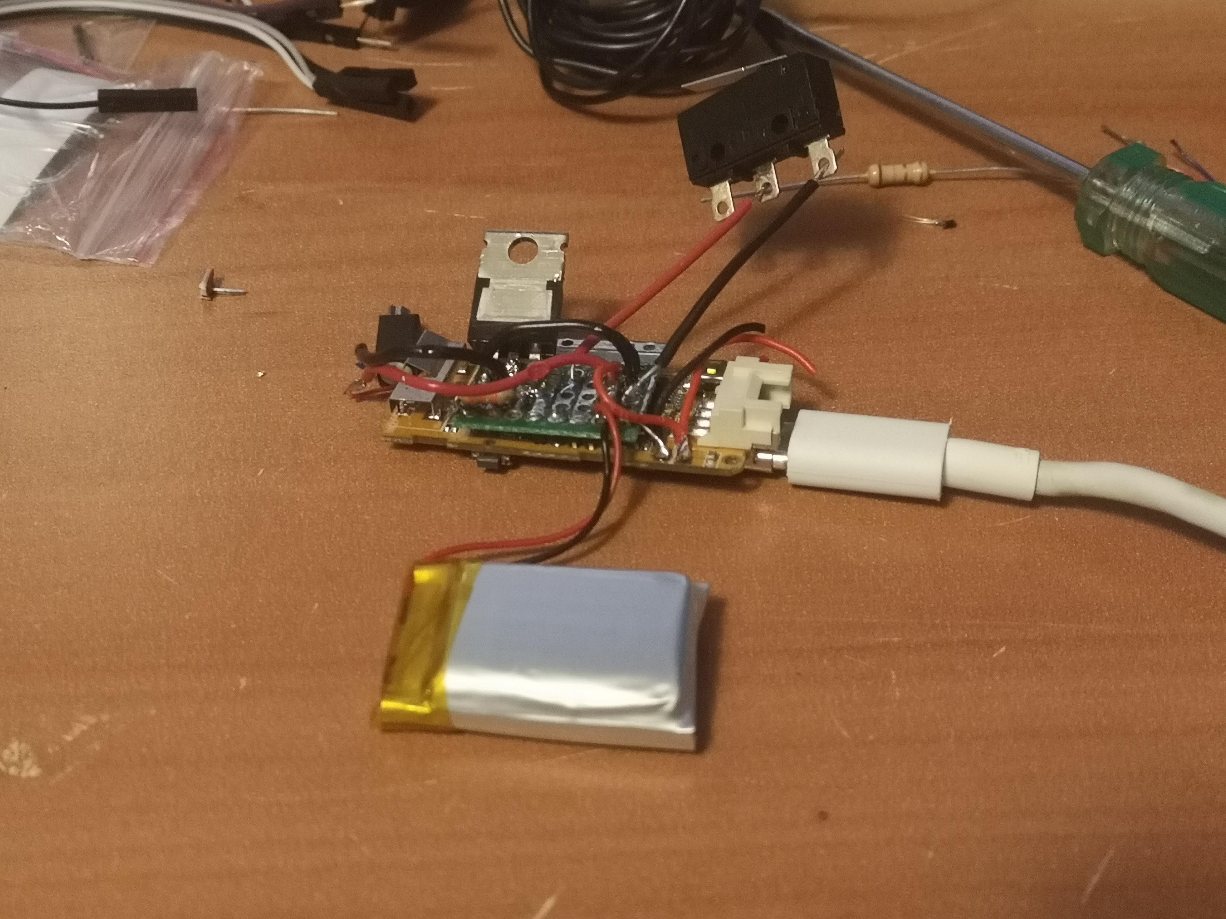
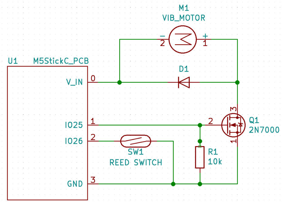
For integrating the vibrating motor and reed switch, I snipped part of a Protoboard and soldered it to some of the header pins, mainly the two GPIO pins that I could identify on the existing PCB. The additional parts were soldered onto this board to make the motor and switch function. Since I broke the reed switch, I replaced it with a limit switch for now. I also only had this one large transistor, which can be replaced with a smaller one. With adding these components in this way, I don't envision the housing size to be increased significantly by the reed switch/vibrating motor integration. The images below show the board itself as well as a schematic of the additional components.
![]()
Replaced the small 85 mAh battery with a larger 400 mAh battery (bottom). Vibrating motor (left) attached to the original PCB via the green Protoboard. Limit switch (top) also attached to the Protoboard, which will be replaced by a reed switch when i get another one. ![]()
V_IN is the positive terminal of the battery, powering both the board and the motor. Pins 25 and 26 are used to control the motor and switch respectively. The device shown above is functional (motor vibrates, limit switch works, battery charges/discharges and doesn't explode, IMU signals send to a receiver). I'm not sure how much time there is left in this project to replace the Protoboard with a PCB. The next task, which is of higher priority, is to work on the packaging of the wearable IMU device.
-
First User Testing Session With UCPLA
08/23/2020 at 19:48 • 2 commentsLast week, we had our first user testing session with UCPLA where we got our first chance to see our prototypes in the hands of our target audience. We were lucky enough to see this firsthand remotely through Zoom and got some valuable learning lessons. A few screenshots from this testing session are shown below.
![]()
Walkthrough of our system. Shared screen mirrors the 7" display in front of the user, currently showing the homepage. Two video feeds on the right side - one facing the keyboard/display and one facing the user. ![]()
Testing the keyboard device to navigate through the maze game. ![]()
Testing the wearable IMU input device to navigate through the maze. This was the first time our devices were in the hands of other people, and it gave us valuable insight into some considerations we didn't focus on. Early on, we asked a few questions to help us better understand our audience, but watching someone try our devices allowed us to better grasp some of these issues.
- Designing for the Caregiver: Almost all of our focus was on the user itself, but there's also a setup procedure involved with our system. There were a few hiccups during the setup where some tasks took a bit longer than necessary. Some of this could be attributed to difficulties communicating through Zoom, some due to doing this trial for the first time, and some could be due to improper user workflow. Before we deliver the final prototype, we need to eliminate that third issue and have proper documentation on how to setup the system.
- Visual Impairment (Keyboard Device): We were told early on that about 50% of users didn't have line of sight, but it wasn't something that was easy to understand. This test gave me a better idea of what this meant. We had a display with the home screen near the keyboard, where the buttons on the keyboard spatially corresponded to images on the home screen layout. My assumption was that the delay for pressing a button was largely due to difficulty controlling one's arm. For this one user, it looked like the delay was just as much visual impairment than it was motor control impairment. First, the user needed to look at the display, then look at the keyboard to recognize which button needs to be pressed. Then, the user needed to move their hand and figure out where it was in relation to the target button. It became a more challenging task than previously thought, and during the maze game with the keyboard device, there was quite a number of wrong buttons being hit. This is for one user and I'm not sure how much this applies to other users, but it is something to consider for future user testing and future design revisions.
- Calibration (IMU Device): There were struggles with the IMU-based device as well. Before using the device, the user needs to go through a calibration sequence. Selecting the correct calibration positions was one thing, and the other thing was remembering those calibration positions during use. During usage, the controller had a difficult time distinguishing between left and right positions, while up and down positions had no issues. This issue was created by choosing the wrong calibration positions, and we need to figure out which calibration sequences will make it easier to accurately select different buttons. A lot of the issues here are to be expected because this is a foreign device that these users have never tried before and a learning curve is necessary. What was most encouraging was seeing how engaged the user was while using the IMU-device. By involving physical movements with a game, it was positive reinforcement to keep trying even though there were a lot of mistakes being made. During this session, physical therapy was brought up as a potential use for this system.
-
One Big Button + Joystick/Keyboard Updates
08/17/2020 at 08:46 • 0 commentsThe last couple of weeks were busy preparing for prototype shipment and I kind of forgot to post log updates, so this entry will cover a few topics. While this upcoming week is focused on user testing and receiving feedback on our keyboard and joystick prototypes, this log will focus on the development of an intermediate prototype of a wireless Bluetooth button.
STARTING SIMPLE WITH ONE BUTTON
![]()
Currently for this project, we were focusing on delivering two prototypes: the keyboard and the IMU-based joystick. I wanted to add an intermediate milestone to create this wireless button prototype, which could potentially be a third deliverable but more importantly serves as learning lessons for future development of other prototypes. Below, I describe 5 discussion topics regarding this one button.
1) Cost of Existing Big Buttons for Assistive Technology
A lot of buttons and switches that are catered towards use as "assistive technology" are in my opinion, really expensive. A big red button can cost about 65 dollars. A mechanical keyboard switch that we are using for our keyboard input device is more than an order of magnitude less that at $1.06. Going one magnitude further, a tactile switch costs $0.10. From an electrical/hardware perspective, they are all just momentary push button switches. Looking at a previous Hackaday project, the Clunke Button, that project addresses this issue by creating a DIY assistive button using a keyboard switch, an audio cable, and some 3D printed parts.
Now taking a look at wireless Bluetooth "assistive technology" buttons, the cost is also expensive with this model priced at $195. I looked at this button, and challenged myself, could I make a button by only having $19.50 to spend on parts? Below are the list of electronics from Digikey to make a wireless Bluetooth button, with the subtotal coming in at $19.36.
Quantity Part # Description Unit Price Extended Price 1 1965-1000-ND ESP32 Board $10.00 $10.00 2 CH197-ND Keyboard Switch $1.06 $2.12 4 SY628-ND AA Batteries $0.33 $1.30 1 36-2478-ND Battery Holder $1.79 $1.79 1 EG5619-ND Rocker Switch $0.57 $0.57 1 CP1-3513-ND Stereo Jack $1.42 $1.42 1 1175-1491-ND Stereo Cable $2.16 $2.16 With these parts, 3D printed parts, and some wires and solder, a Bluetooth button with an stereo jack to connect another "Clunke" style DIY button can be made at almost 1/10th of the cost of a commercial alternative, and 1/3rd the price of a just a button. Below is a snapshot of the CAD model with a section cut out and an image of trying to get all the electronics to fit inside the 80x65x52.5 mm housing.
![]()
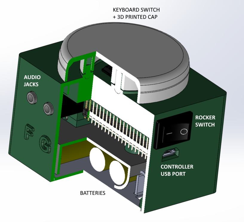
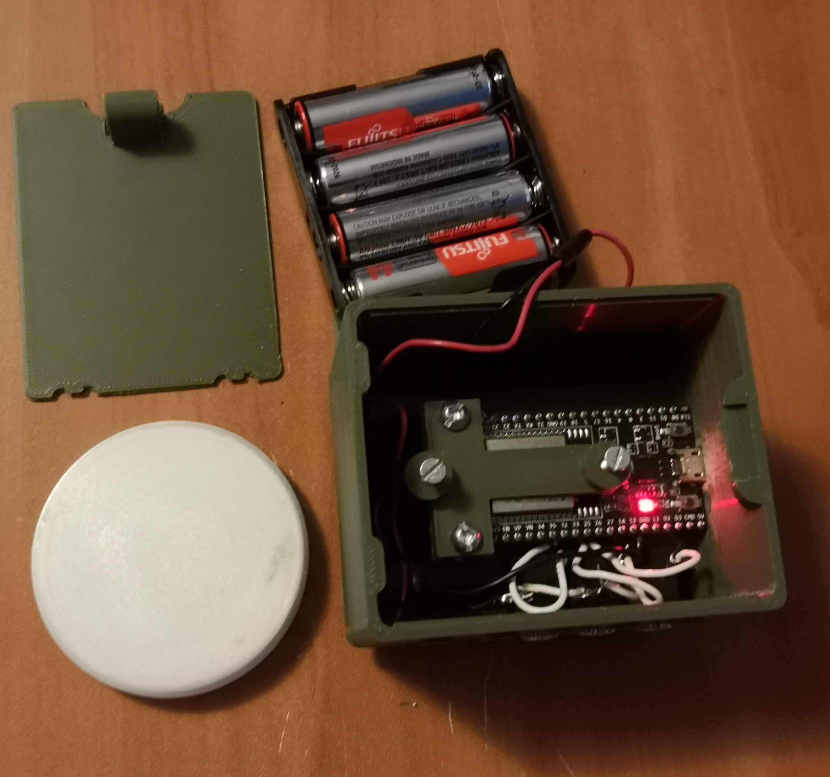
CAD model of button and housing. Rocker switch turns on battery mode. 3 audio jacks included (10 total ports available) for connecting external large switches. Access to usb connection to upload new firmaware or to run button of wall power. Most of the housing weight and size is taken up by the batteries, which could probably be reduced. ![]()
Opened up housing with battery compartment taken out. Not a lot of spare room if 10 audio jacks are used. I made a mistake for this model, and there's some interference where I can only install up to 6 jacks, 3 on each side, for this model. So with $20 worth of electronic components, we can make a $200 button that has Bluetooth connectivity to be used with our platform we're developing. This leads to the next topic, why have just a simple button instead of the other cool devices we're developing?
2) Asking users to deviate from their unique behaviours and tendencies
The keyboard and IMU-based input devices we're developing aren't necessarily commonplace in the assistive technology market. Even if we're designing these devices that we think have added functionality or an improved user experience, it doesn't mean our devices are going to be adopted by potential users. My guess is that there will be a large population that are comfortable using their existing devices and are unwilling to adopt to ours. Thus, it would be helpful to have this iteration that is simple and recognizable to connect their existing input controls to access digital devices through our developing platform. Sometimes, less is more.
3) Maximizing functionality of one button (and then multiplying)
While uploading firmware for this iteration, I was thinking about how to expand the functionality given just one button. There is an Arduino library, OneButton, that helps with this. It can help program a button that distinguishes between a short and long button press, as well as the detection of a double click. With this, one button can now have the capability of 3 buttons.
For users who may have less motor control function, the single click vs double click detection might not be the most suitable as it often requires a delay for a double click. I'm expecting a longer delay between two sequential button presses. I'm not sure it is the best idea to ask someone to press twice quickly given certain individual's motor abilities. Thus, I plan on focus on adding functionality by distinguishing short and long presses, and extending this concept further.
What I hope to integrate is to send pulse vibrations at set time increments (1 -2 seconds or user-defined?) while a button is held down. I think a user would be able to hold down a button, count the number of pulses they feel, and then release it after a certain number of pulses to hit that specific "button". I think this is a way we can extend the use of 1 button to 2 or 3 or 4. Yes, it takes longer to press a button if it takes 5 seconds to hold down. However, if a user was asked to reposition their hand away from their button they are hovering to another button and hit that, that action might also take 5 seconds depending on the user.
4) A Panic Button
In one of our recent meetings, we discussed the possibility of using our platform to keep caregivers and users remotely interconnected. As we are trying to give users more individuality by being able to control digital devices, this will hopefully give their caregivers more confidence to leave the users alone more often for extended periods of time.
With more individuality, hopefully users can be less dependent on their caregivers allowing for more freedom to do other things. If the caregiver and user are physically separated, we can leverage the power of IoT to keep the two interconnected at all times to give both caregivers and users peace of mind. The simplest implementation is to give the user an emergency button, where if the user requires immediate attention, it can press the button to send a text message/email to their caregiver, prompting them to check in. A future implementation that makes more sense is to connect to a camera for remote monitoring. For now, the focus is to get some feedback to see if having an emergency button to send a text message is helpful for different users and caregivers.
5) Button box as a Surrogate for IMU Device for Debugging
Developing this wireless button is helpful for learning lessons to help development of other prototypes, specifically the IMU system. This button box and the IMU joystick share similarities, including the use of the same microcontroller and having 4 buttons. While I experiment with things such as planning a intuitive user workflow and the wireless communication protocol between the platform brain and the input device, I can use this button box to do the debugging. The mistakes and lessons learned can then be applied to to joystick and keyboard prototypes. Also, making this button box was helpful for me because I haven't soldered anything in like a year and was tinkering with a new 3D printer, so I had some rust to shake off before starting the hardware development of the joystick.
JOYSTICK UPDATE
The first prototype that was shipped for testing was an out of the box system, the M5StickC unit. On the hardware side, a lot of upgrades can be made for the next iteration. Three planned upgrades are to increase the battery capacity, including haptic feedback, and integrating a switch to toggle between "states". In addition to these three components, the user testing that will be conducted this week will be instrumental in helping design the packaging and ergonomics consideration of this system. For instance, I am not convinced that all users are comfortable wearing a device for 10 hours a day.
Battery
Within the M5StickC, a small, 85 mAh battery is used to power the device. This device powers the chip (ESP32 Pico), the IMU (MPU6886), and other components (RTC, TFT display, LEDs, etc.). With this small battery running the firmware to stream IMU data to a receiver at a sampling requency of 20 Hz, the device runs out of power in about 10-15 minutes. With a larger battery connected, I played around with the sampling frequency to see how it affcected the device runtime.
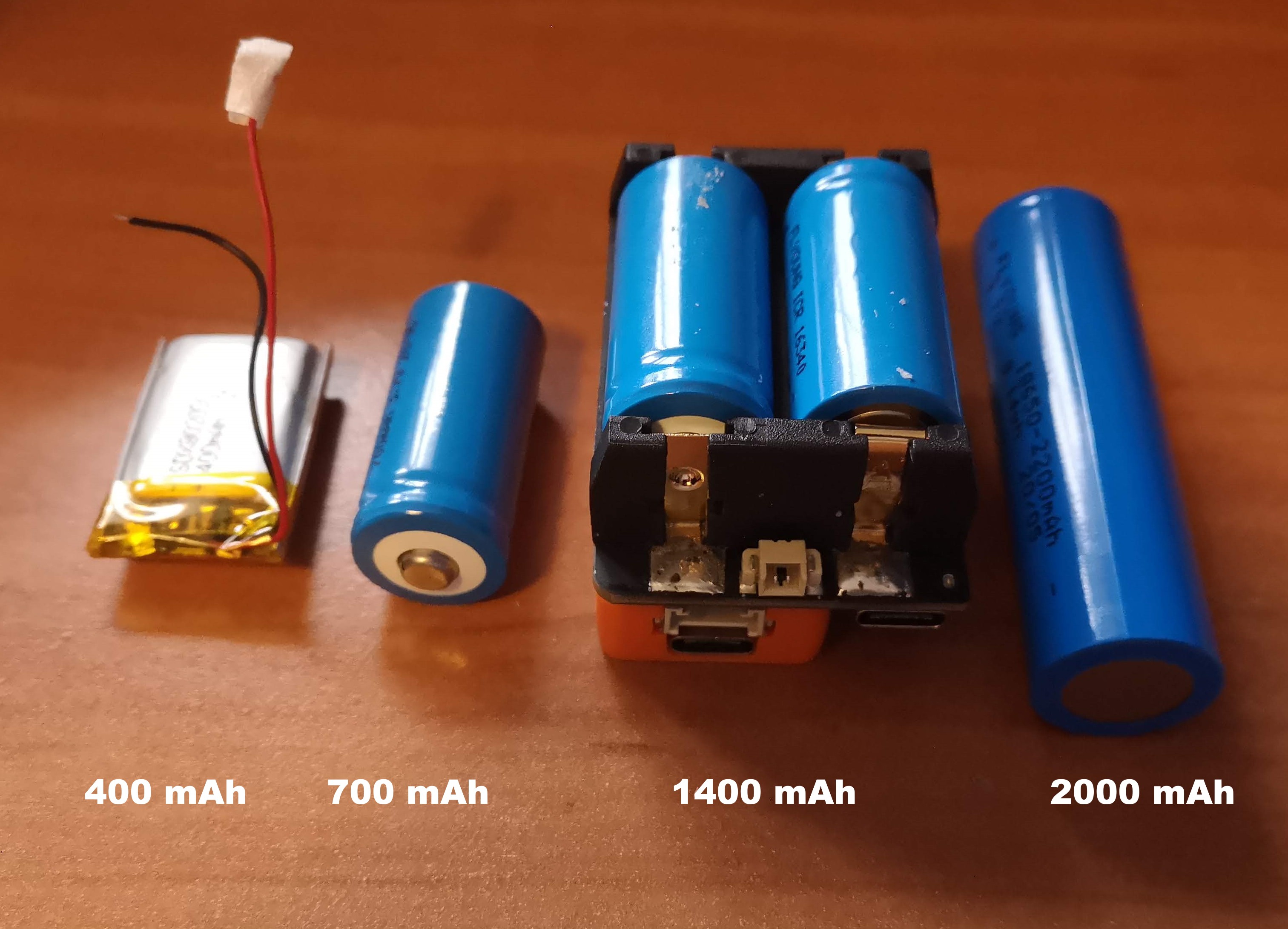
Battery Capacity Sampling Frequency Device Runtime 85 mAh 20 Hz 0 hrs 15 mins 1400 mAh 20 Hz 7 hrs 30 mins 1400 mAh 10 Hz 8 hrs 45 mins 1400 mAh 5 Hz 10 hrs The next battery test I want to do is to replace the M5StickC device with the ESP32 development board and an IMU sensor, to see if the battery is powering unnecessary components. I've already tried to power off as many of the M5StickC components including the TFT display, but I'm guessing there are unnecessary components that are consuming power. My aim is to find the right parameters to get enough runtime of say 5 hours in active usage state. With a larger battery capacity, it also increases the battery size, which would dictate the size of the housing as well. Below are some of the few battery options being considered, while also continuing to search for other options as well.
![]()
Switching States from Deep Sleep to Active Mode
A useful functionality of ESP-based boards is the low power consumption during deep sleep modes. Looking online for different tutorials, this implementation seems straight forward for switching states using an external button trigger and is something I plan to play around with in the upcoming days. This button trigger could be something like the one big button device, but I was thinking of using a low profile, non-contact switch. Some ideas include mounting a magnet near the user and connecting a reed switch to the microcontroller, or doing something with proximity sensors. Regardless of the approach of the button trigger, I plan to implement the concept of holding down a button and sending pulses at timed intervals for switching between active modes and deep sleep states.
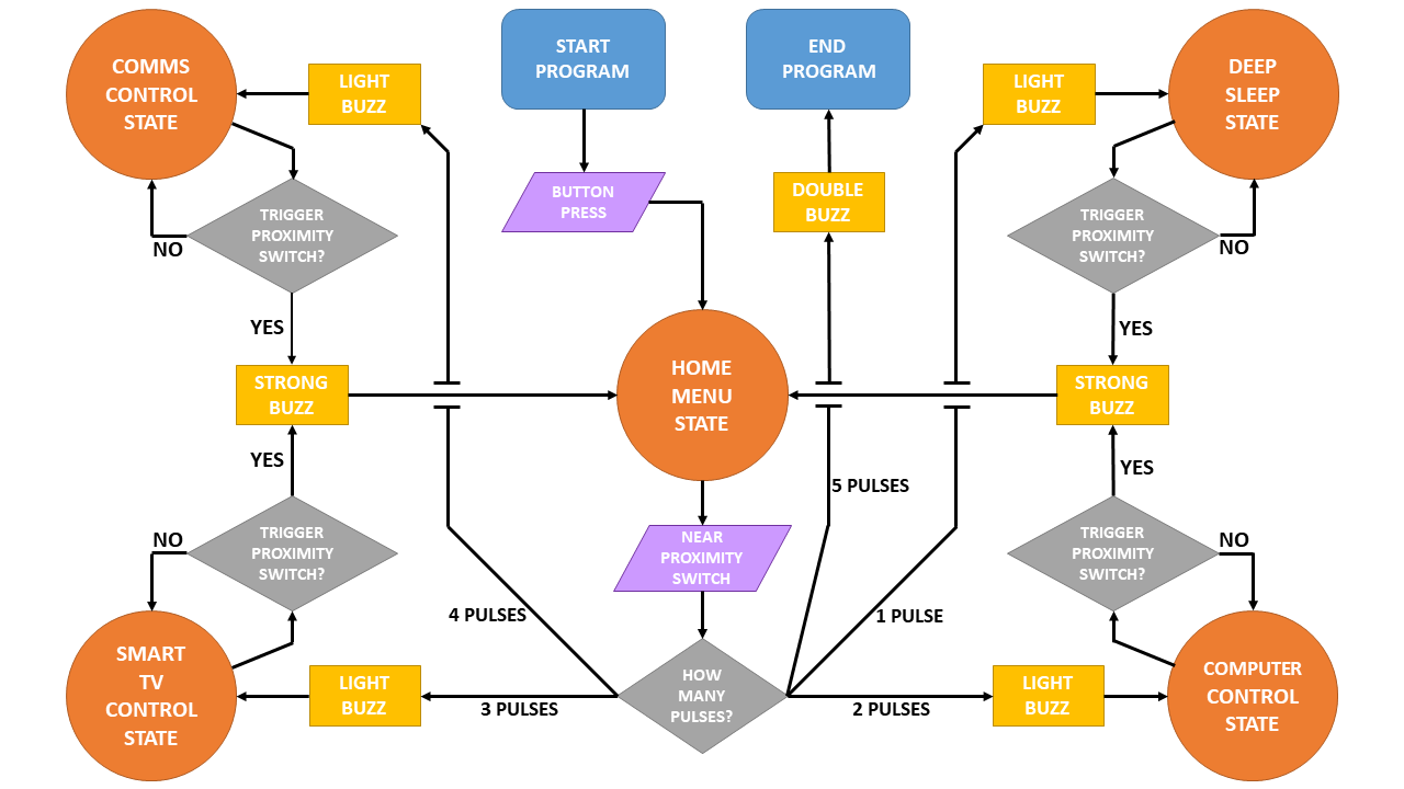
The figure below is a flowchart/state diagram to switch between device states. It started as a programming flowchart, but then it seemed to make more sense to show it as a state diagram, so its kind of a confusing hybrid.
![]()
In each state, the joystick is running its own subroutine for controlling the digital device. To switch from one state to another, feedback will be indicated by pulses from a vibration motor. The initial plan is to have a magnet in a fixed location on a wheelchair, where a user hovers the device near this magnet to trigger and toggle states.
This toggling between states is something to be considered for all input devices to switch between peripherals. For the keyboard based input device, the UX becomes easier since there are more buttons available that can be dedicated to state switching.
KEYBOARD UPDATE
The last topic for this update is on the keyboard input device, which was the focus of development a few weeks ago. The current status of this prototype is awaiting feedback from user testing. Potential next steps include moving from a tethered USB connection to a Bluetooth connection, determining the best UI/UX flow, and being able to control a Roku remote with this keyboard. Once this Roku connection is established, we can work on adding this functionality to the IMU-based device as well.
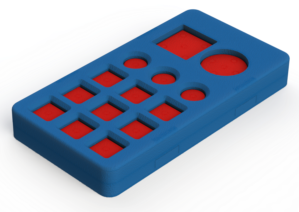
Here are some images from the CAD development of the keyboard from a couple of weeks ago.
![]()
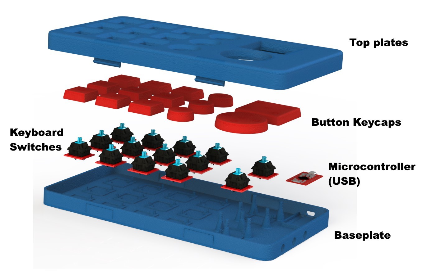
Keyboard render ![]()
Exploded view with labels for different components of keyboard device ![]()
GIF animation of exploded view of keyboard device. ![]()
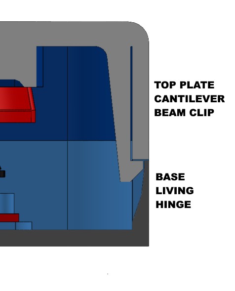
Cross section showing cantiliver clip used to mate top and bottom housing for easy assembly/disassembly without external tools Lots left to do and not a lot of time left. Last few weeks will be busy!
-
Package Delivered
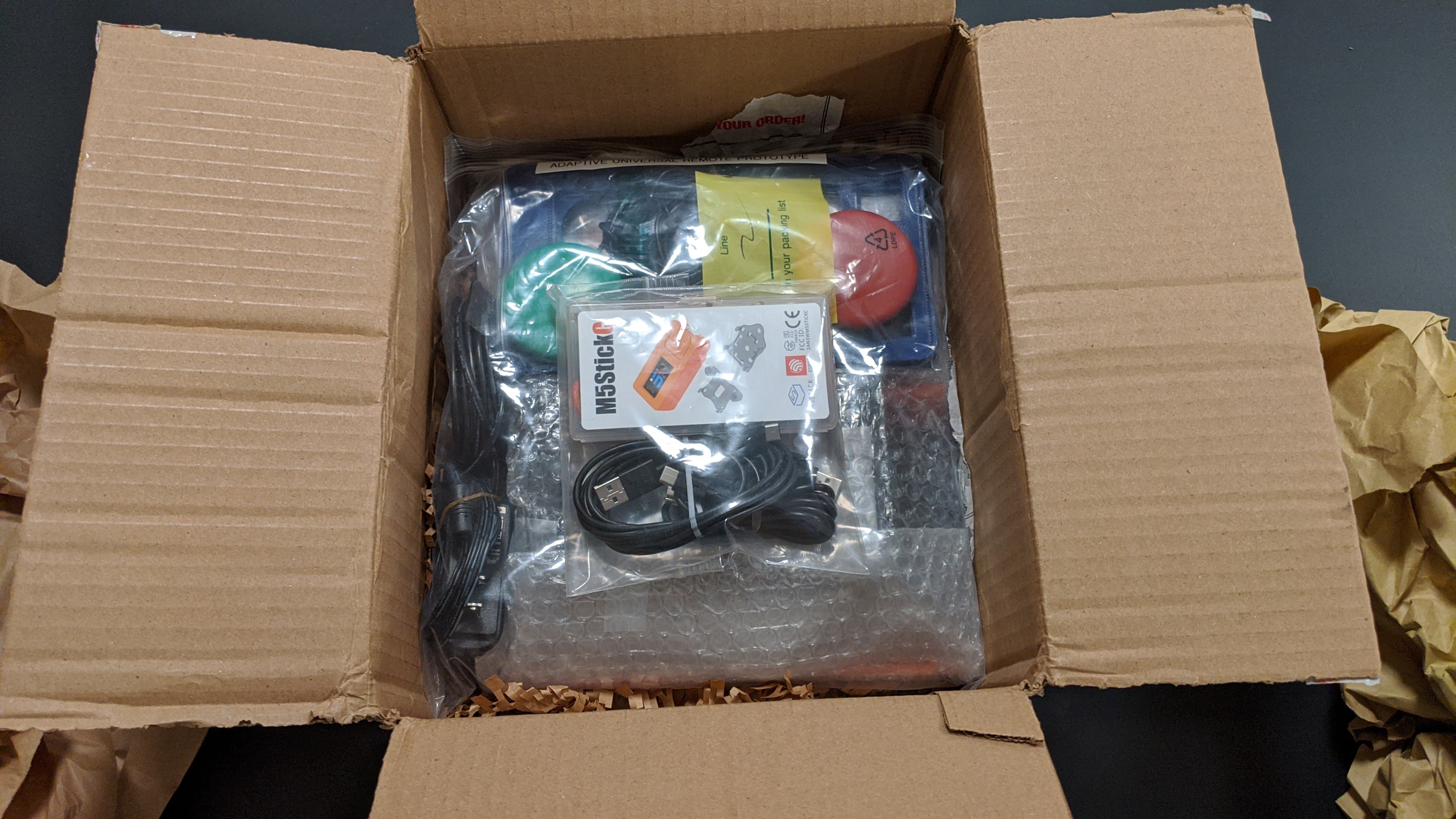
08/15/2020 at 01:42 • 0 commentsAragna From UCPLA Has Received The Package
![]()
We had a meeting to go over all of the content and have Aragna set everything up to be sure it was all working. While we did have everything he needed in the box, I soon discovered that I should have labeled all of the cables.
Our goal for the final version is to eliminate all of the cables.
Another lesson learned was that I should have double checked the address before shipping. At second glance I would have noticed that the address was missing some information (apt #). Even so we lucked out and the package was still delivered in time for our meeting.
Also, I need to do better at tacking screen shots during a session.
Trying to Demo over a Web Meeting
Other than the slight confusion of which cables to use where (The joysticks came with three USB-C cables), The demo went well. Once challenge when showing a demo is trying to align the camera to give your viewers a good view of the items you are using.
One way we were able to kind of work around that was by having me screen share my remote connection to the display unit. That way the team could see what the device was doing as Aragna was testing it out.
Over all I say it was a success!
We already have a meeting lined up with our first user this Monday.
-
Concept Prototype Ready To Ship
08/10/2020 at 20:28 • 0 commentsM5stickCs and Atom ESP32 as cordless joysticks
![]()
At the moment these will be used to gather more user data, to help design a full on wireless joystick.
Raspberry Pi Computer with display running our Demo Software![]()
Running our Universal Remote Demo Software to show the concept of how we plan on assigning many actions to only a few buttons. The UI will match the button layout, then each button on the custom keyboard will correspond to button in the UI. (To test this with a keyboard, use the following keys

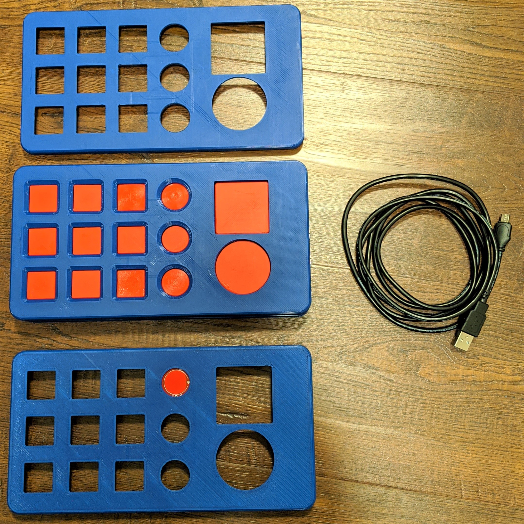
Custom Adaptive Keyboard Test Kit
![]()
It is simply a custom keyboard with only 14 keys. The design is more about giving our potential users a functional test kit, so they can feel the difference between the keys and decide on which button type, size, trigger force, and recess level they prefer. We also modified two of the buttons by adding a much stiffer spring. (I didn't get the chance to measure the actual force so the values are guesstimates.)

Cherry MX Switch Table
Switch Actuation
ForceLinear Tactile Clicky Used For Red 45g Yes No No Gaming Brown 45-55g No Yes No Typing/Gaming Blue 50-60g No Yes Yes Typing Black 60g Yes No No Gaming Green 70-80g No Yes Yes Space bar White 75-80g No Yes Yes Typing Grey 80g No Yes No Typing/Gaming Linear Grey 80g Yes No No Gaming -
Keyboard Matrix Scanning
08/06/2020 at 18:09 • 1 commentEarly in my college years I came across this very useful and web based animated circuit simulator, falstad.com/circuit. Since I'm a hands on and visual learner, this tool really helped me grasp the behavior of electronic and logic circuits.
While I was working on the firmware for our concept prototype keyboard, I thought it would be fun to create an animation of how keyboard matrix scanning works.
![]()
Click on the image or here to visit falstad.com/circuit and try it out for yourself.
As you can see the micro-controller drives the rows low one at a time and reads the columns as inputs. If both the row and the column are low, then a key-press is detected.
This allows us to read key presses without needing a single input for every single key! In this example we are able to detect key presses for 15 keys with only 8 GPIO pins. Almost all keyboards or TV remote controls follow the same principle.
You can also check out our Arduino code for the keyboard test-kit at the Github project.
-
IMU Joysticks V2: Calibration Routines and Flag Semaphore
08/02/2020 at 23:02 • 1 commentIn the first log of this project, I experimented with IMU sensors as alternative input methods to large buttons and mechanical joysticks. Along with the smart remote prototype we are working on delivering to UCPLA for testing, we want to also deliver an IMU-based input controller as well. In this log, I will discuss the software updates making the joystick more robust and usable for different users.
Previous Iteration
In the first iteration, the code was quickly written to make things barely work enough to demonstrate a concept. For example, raw IMU signals (accelerometer only) was used and threshold values were hardcoded specific to how I wanted to use it. Three improvements are made. First, the raw IMU signals were processed to smooth out the signals to give better results. Second, a calibration routine was programmed and a new thresholding technique was used to detect different position states. Last, a two joystick controller was shown to demonstrate modularity and the ability to expand input capabilities.
The hardware did not changed from the previous iteration. All of the processing is done with a receiving unit, an ESP32 based board. Two M5StickC units ( with an IMU sensor, button, and screen) send signals to the receiver. In this iteration, one M5StickC unit is intended to be worn on a user and the other unit is intended for the caregiver for handling calibration of the system.
Lightweight Signal Processing for Smoothing Data
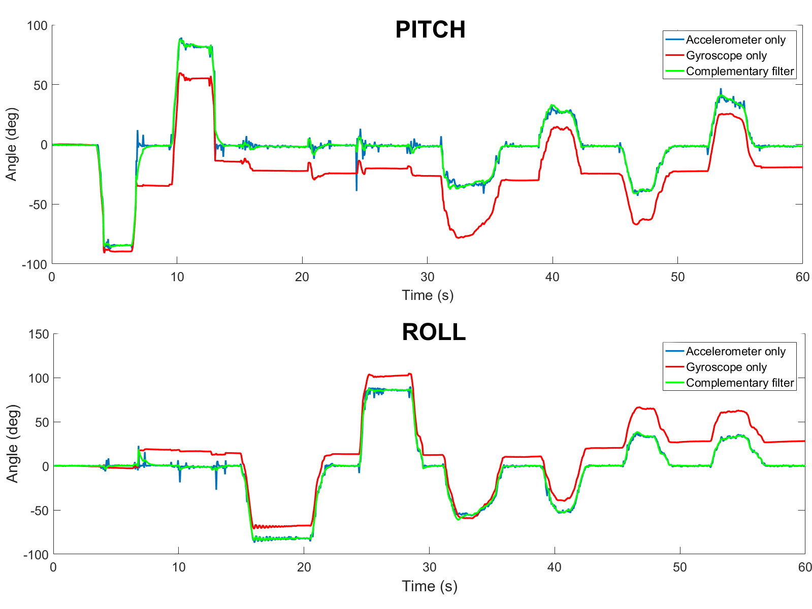
The IMU in the M5StickC is a 6-DOF IMU, with 3 accelerometer signals and 3 gyroscope signals. With this IMU, all I am trying to do is measure tilt of the unit. The first iteration measured tilt only using accelerometer signals, which is not the most accurate way to measure tilt angles. The problems with measuring tilt from accelerometer signals is any sort of movement including vibration will cause noisy signals.
Tilt angle can also be measured using signals from a gyroscope, with signals measuring the angular velocity. Calculating orientation from gyroscope can be done by integrating the gyroscope signals. The issue with doing the angle drifts from the correct orientation over time.
The most common technique to calculate tilt angles using IMUs is using a Kalman filter to combine accelerometer and gyroscope signals. However, I opted to use a complementary filter which is stupid simple to implement and doesn't need a lot of computation. It combines both methods together to mitigate both noisy signals and IMU drift. Some more detailed info on complementary filters and IMUs in general is found here, which I followed to implement for this system.
The image above compares the three methods to measure angles based on accelerometer and gyroscope data from one of the IMUs.
Adding a Calibration Routine
The next improvement that was necessary was adding a calibration routine to make this system more robust. Considering that each user with cerebral palsy has different limitations, they won't all be able to use this input device the same way. Thus, a calibration routine is necessary to stay within their motion limits. In my head, the plan that makes sense is to involve a caregiver for setting up the IMU. The IMU will be strapped onto an extremity with decent range of motion. The caregiver will then instruct the user to move in different body positions with each position corresponding to a different button. The caregiver will have a second M5StickC unit, which will give them prompts on a display and a physical button to press to help with calibration. Once calibrated, the information will be written onto the flash memory of the receiving microcontroller to store until the IMU is re-calibrated again.
Once calibrated, the IMU is ready to use immediately. For this initial test (and the first test with users from UCPLA), I wanted to keep it simple and limit the buttons to the four arrow keys on the keyboard. With these hotkeys programmed, I wanted to demonstrate the usability by different users, represented by a quick re-calibration that allowed me to transition the control from my knee to my hand. This is shown in the video below.
This example of playing a game to navigate a car through a maze was chosen specifically to mimic the use of a mechanical joystick to drive a wheelchair. In the future if this system continues to develop, playing a game like this would help benchmark the usability of this system compared to using a mechanical joystick.
With a calibration routine, the method to identify the different body positions changed accordingly. In the first iteration, raw signals were thresholded (if signal>threshold1 -> hit button 1, if signal < threshold 2 -> hit button 2, etc.), which isn't the ideal way especially when trying to scale.
In this iteration, the method was to calculate the root mean square error, comparing between the instantaneous angles (roll, pitch, yaw) and each of the 5 positions(LEFT, RIGHT, UP, DOWN, and NEUTRAL) stored from the calibration. The minimum error from the 5 positions was chosen as the current state.
Adding a Second IMU to Increase "Buttons"
I envision this system being very modular and scalable. If a user only has decent motion in one arm, then maybe they can only use one of these units. However, if a user has motion in both arms (forearms, upper arms, hand) and legs, the possibilities with this system is endless. To demonstrate scalability, a second joystick was introduced.
In this case, I wanted to demonstrate the ability to replace a keyboard to type. One discussion topic for designing the smart remote was how many buttons we should include. With more buttons, the remote gets larger. With fewer button, the user has less control. A keyboard has about 70-100 buttons, so if we had a remote with 100 buttons it would be pretty large.
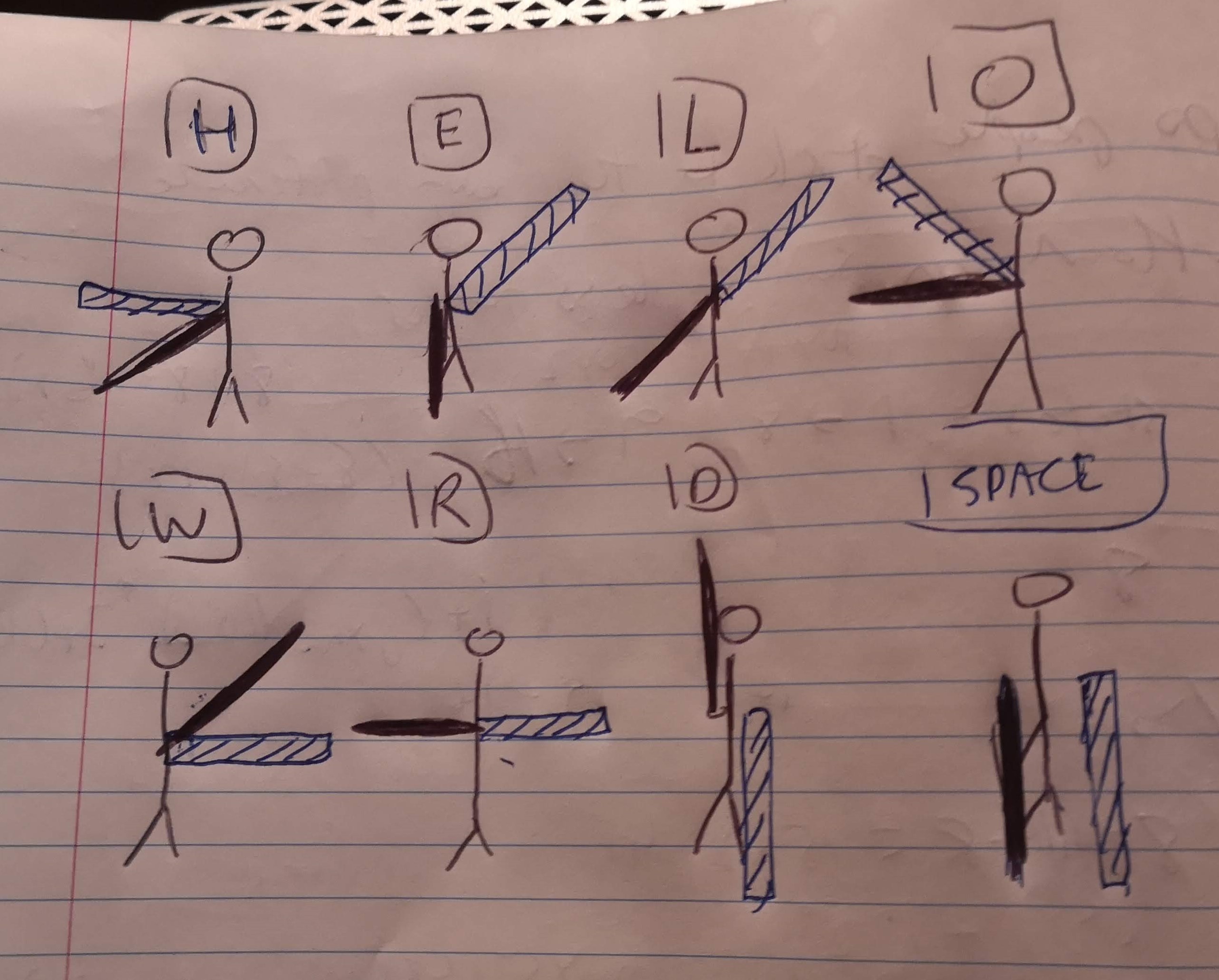
Using two IMUs, I replicated the flag semaphore system to have full capabilities of the English alphabet and more. With this system, arms (and flags) are pointed outward from the body at 45 degree increments of each other. With each IMU, I first calibrated 7 positions, (meaning 14 total positions from 2 IMUs). I didn't show this calibration routine but it is the same as what was shown in the first video, except now both units stream IMU data to the receiver. With two IMUs with 7 position, this gives 7x7=49 unique buttons that can be pressed, more than the 26 needed for the alphabet. For the first test, I used the semaphore system to type "HELLO WORLD", shown in the video below. I might have inverted the positions, so I attached an image of the corresponding system used in the video.
![]()
With more positions, it becomes more difficult to map the correct orientation to the right output, so an extra delay was added to ensure less mistakes. With users from UCPLA, this becomes even more of an issue if they have less motor control and is something that needs to be thought about more. Although I think it would be neat to have this system replace a keyboard input device, this might be too much to troubleshoot for the initial test with UCPLA. For the first test that is coming up very soon, work still needs to be done to improve mounting options instead of taping IMUs to the body as well as determine specific testing plans and goals.
-
Smart Remote Button Sensitivity
07/28/2020 at 07:32 • 3 commentsAs Ruben alluded to in a previous log entry, one of the first proof-of-concept prototypes we want to deliver for testing is a smart remote with an array of 15 buttons. Depending on how a user decides to hit a button, a parameter we want to play with is how much force or effort it takes to hit a button. For me typing on a keyboard, I have pretty good control of all my fingers and won't mistakenly hit the wrong keys. In my case, I would want something with low resistance and low force. If we are designing for somebody with less motor control, mistakenly hitting wrong buttons (false positives) is a concern with regular remote control designs. One way we can avoid hitting wrong buttons is changing the button sensitivity to make them harder to press.
The main button type we have keyed in on are mechanical keyboard switches. Advantages of using these buttons are they are extremely common to find, come in a standard size, can withstand millions of cycles, and have a relatively low profile compared to other options we were considering (arcade buttons, limit switches, etc.). We were also thinking of making our own switches if we wanted a low profile button, but at least for this first prototype, it's not the highest priority.
For a mechanical switch where the button is either on or off, how do we change sensitivity? If we had an analog "button" like a force sensor, we could change the sensitivity on the software side by simply adjusting the pressure threshold. Similarly for a mechanical switch, the way we would do this is by changing the spring stiffness inside the key. Cherry MX sells a bunch of different types of key switches with varying parameters such as actuation force (sensitivity) and key travel distance. We have ordered 9 different types of buttons to use in our test panel to vary some of these parameters, including button sensitivity. However, after thinking about it some more, the actuation force of different key switches really didn't vary too much. From their website, all of the keys' actuation force lied within the range of 45-80 gF. Even though we ordered a bunch of different keys, the actuation force didn't span a broad enough range. We decided to first open up a key switch to see how feasible it was to replace the spring with one that was stiffer.
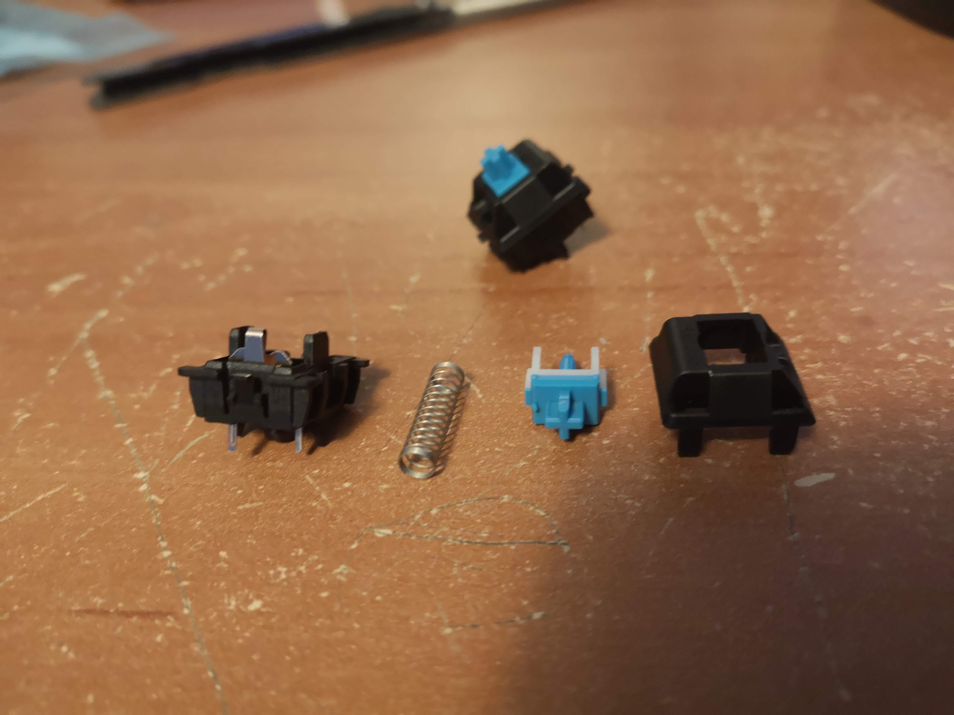
![]()
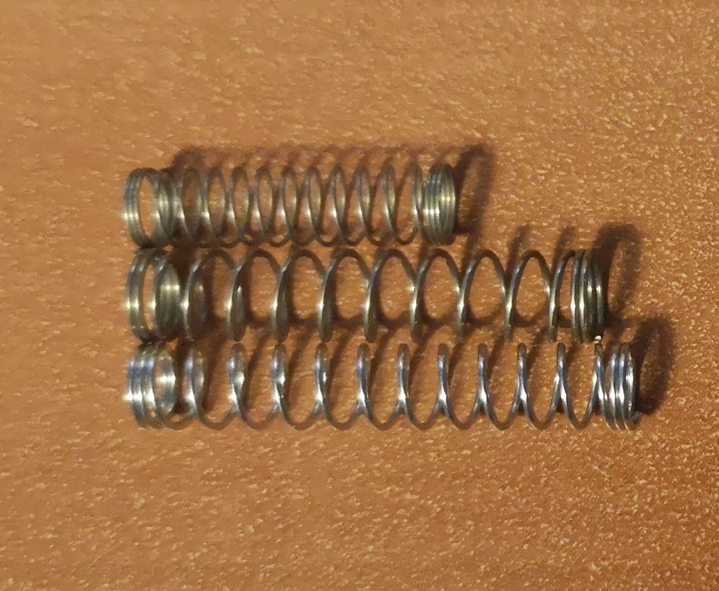
Disassembled keyboard key switch. Components from left to right: 1) Bottom housing with electrical contact pins 2) spring 3) actuating component and key cap mount 4) top housing. It turns out these keys are really easy to open and are relatively simple to disassemble with only 4 components, one being the spring. By replacing the spring with another with a different spring stiffness or length, the hope is that we can have much stiffer keys switches that is at least an order of magnitude higher than the original switch. As a quick test, two springs were pulled out from ballpoint pens. Below is an image of two longer and stiffer springs, compared to the shorter spring from the key switch.
![]()
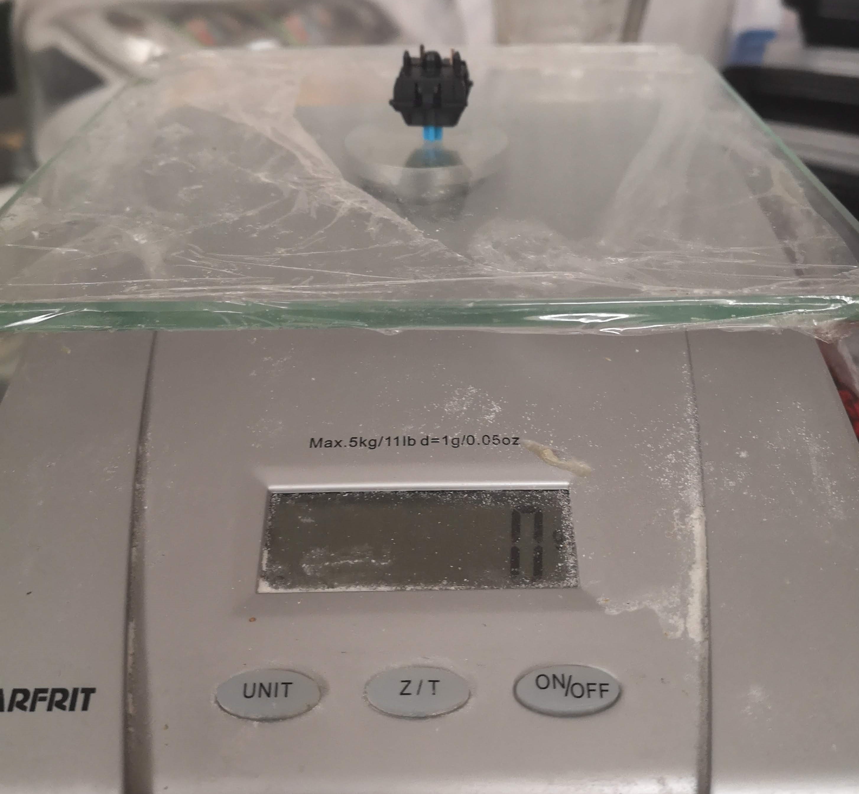
Top spring is the original keyboard spring and the bottom two are from ballpoint pens. Factors affecting spring stiffness include wire diameter, coil diameter, and number of turns. Each of the springs were installed inside the key switch to test the actuation force required with each spring To estimate this force, a kitchen scale was used. The first test was with the original short spring that came with the key switch and it required about 50 gF to actuate. The rated force from the website is 45 gF, so this was pretty good validation for using this kitchen scale for measuring force.
![]()
Makeshift actuation force measurement setup with a kitchen scale. The next two videos show testing of the springs from the ballpoint pens. For the longest spring, I had trouble closing the housing, meaning I probably exceeded the fully compressed length allowed inside the housing. Regardless, testing of both springs showed actuation forces of about 450 gF and 600 gF, which was the order of magnitude increase I was hoping for.
The next step was to find a source of springs to integrate within our proof of concept prototype buttons. From Mcmaster Carr, I selected a few springs and made a quick calculation based on the specifications of the actuation force required to actuate a switch. Based on the constraints of the housing, any spring should have an outer diameter between 3-4.3 mm with a fully compressed length less than about 5 mm. The key assumption that was estimated was that the housing confines the spring to a height of 7.5 mm in the key's unpressed state. This estimate was guessed based on dimensions from Cherry's developer page. With this assumption, the equation to calculate the actuation force is the spring equation:
where k is the spring constant, L is the length of an uncompressed spring, and d is the housing's height confinement of 7.5 mm. With this simple equation, I selected 5 springs that fit the housing constraints and were evenly spread out in terms of actuation force, summarized in the table below.
# Spring Length (in) Spring Constant (lb/in) Force (lbF) Force (gF) 1 0.375 5.2 0.416 189 2 0.625 2.6 .858 390 3 0.625 4.1 1.353 614 4 0.75 5.0 2.275 1033 5 0.625 10.8 3.564 1618 If these forces are correct, there's a good chance the force required to actuate spring #5 would not be able to be contained by the key's housing clips. Regardless, it's worth a shot to see how far we can push the limit. The next step for this prototype is looking at the full assembly of the board, including the recess plate which works in tandem with the button sensitivity to prevent hitting wrong buttons. This will be discussed in a future log once we make more progress on that end.
2020 HDP Dream Team: UCPLA
The 2020 HDP Dream Teams are participating in a two month engineering sprint to address their nonprofit partner. Follow their journey here.