 Leonardo Ward
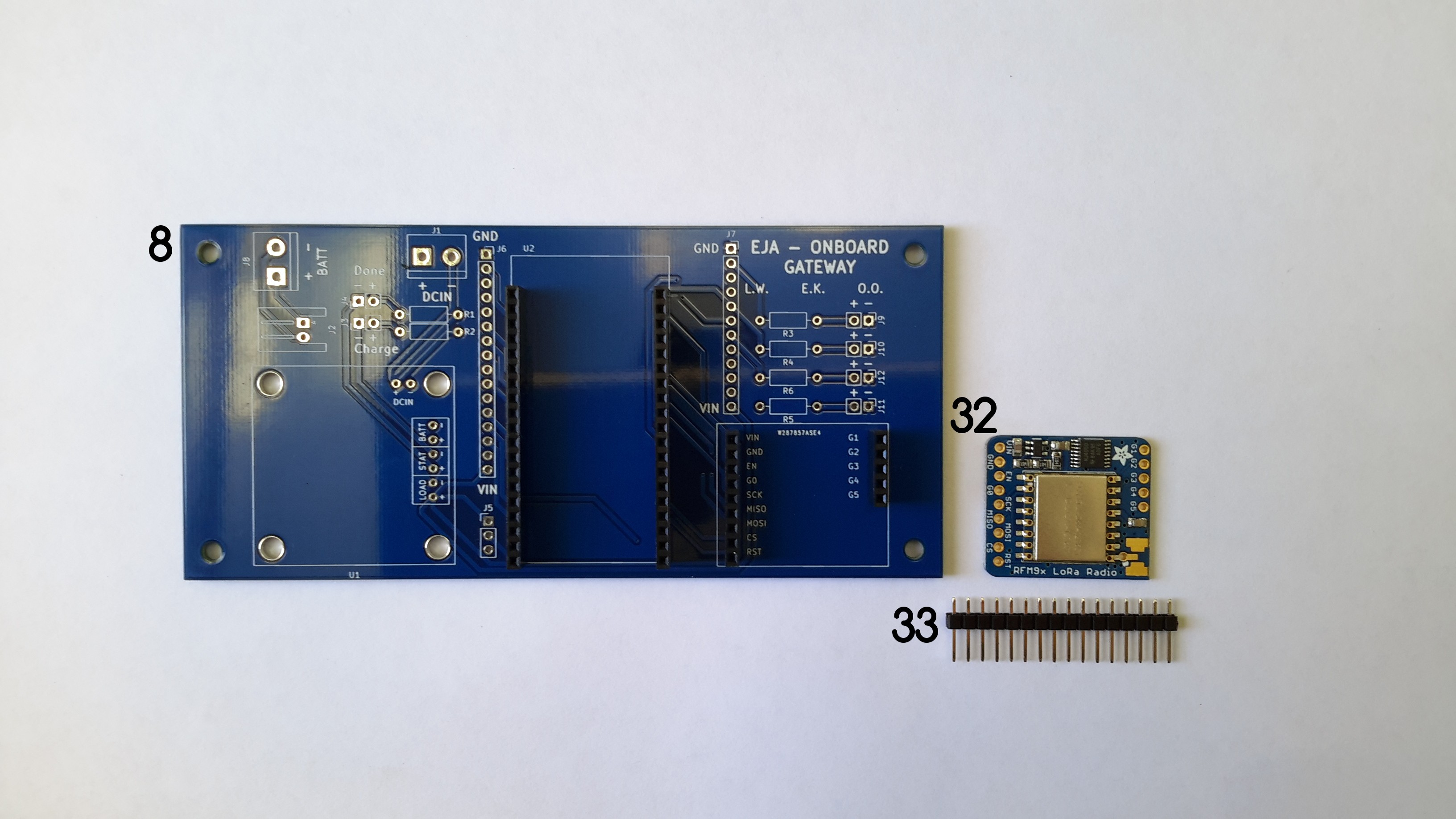
This log describes the recommended assembly instructions for the Onboard Gateway V1.0 PCB. The following image shows all the required components, with an identification number that will be used in the log.
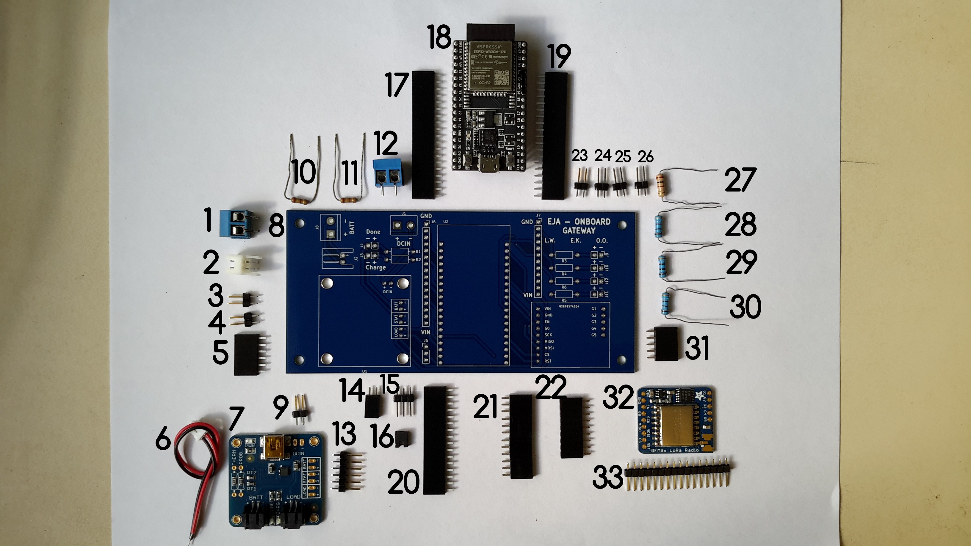
Components list:
- TERM BLK 2P SIDE ENT 5.08MM PCB
- CONN HEADER R/A 2POS 2.5MM
- CONN HEADER VERT 2POS 2.54MM
- CONN HEADER VERT 2POS 2.54MM
- CONN HDR 6POS 0.1 TIN PCB
- 2POS JST cable (included in the USB LiIon/LiPoly charger)
- USB LiIon/LiPoly charger
- Onboard Gateway V1.0
- CONN HEADER VERT 2POS 2.54MM
- 250 Ohm Resistor
- 250 Ohm Resistor
- TERM BLK 2P SIDE ENT 5.08MM PCB
- CONN HEADER VERT 6POS 2.54MM
- CONN HDR 2POS 0.1 GOLD PCB
- CONN HEADER VERT 6POS 2.54MM
- CONN JUMPER SHORTING .100" GOLD
- CONN HDR 19POS 0.1 TIN PCB
- ESP32-DEVKITC-32D
- CONN HDR 19POS 0.1 TIN PCB
- CONN HDR 16POS 0.1 TIN PCB
- CONN HDR 12POS 0.1 TIN PCB (I used 2 CONN HDR 6POS 0.1 TIN PCB)
- CONN HDR 9POS 0.1 GOLD PCB
- CONN HEADER VERT 2POS 2.54MM
- CONN HEADER VERT 2POS 2.54MM
- CONN HEADER VERT 2POS 2.54MM
- CONN HEADER VERT 2POS 2.54MM
- 100 Ohm Resistor
- 100 Ohm Resistor
- 100 Ohm Resistor
- 100 Ohm Resistor
- CONN HDR 5POS 0.1 GOLD PCB
- RFM95W LoRa Radio
- CONN HEADER VERT 16POS 2.54MM (included in RFM95W LoRa Radio)
It is possible to solder the components in many different orders, I'll describe the one that I followed, it can used as a reference.
Instructions
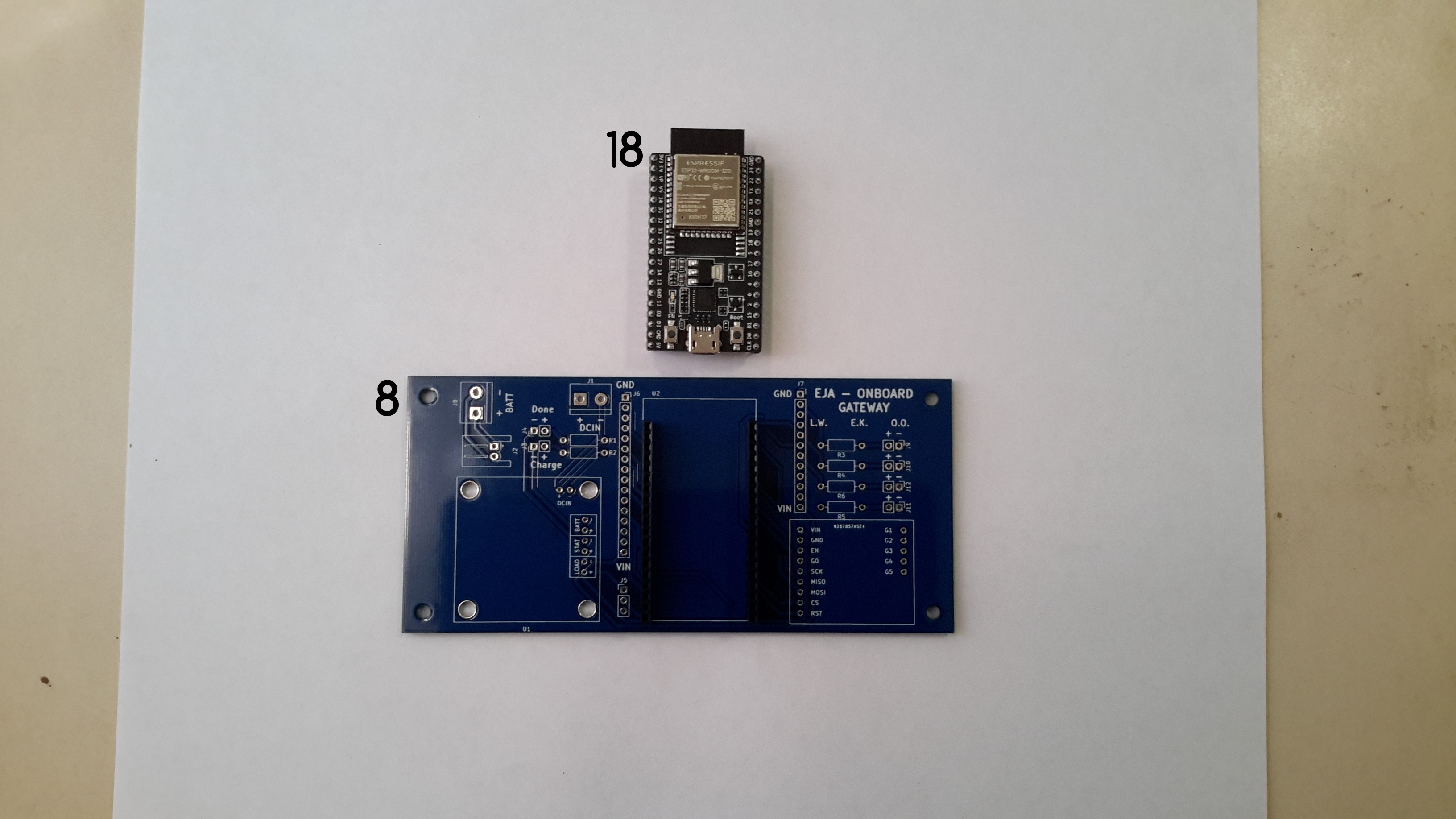
a. Solder the female headers 17 and 19 used to connect the ESP32-DEVKITC-32D to the Onboard Gateway V1.0.
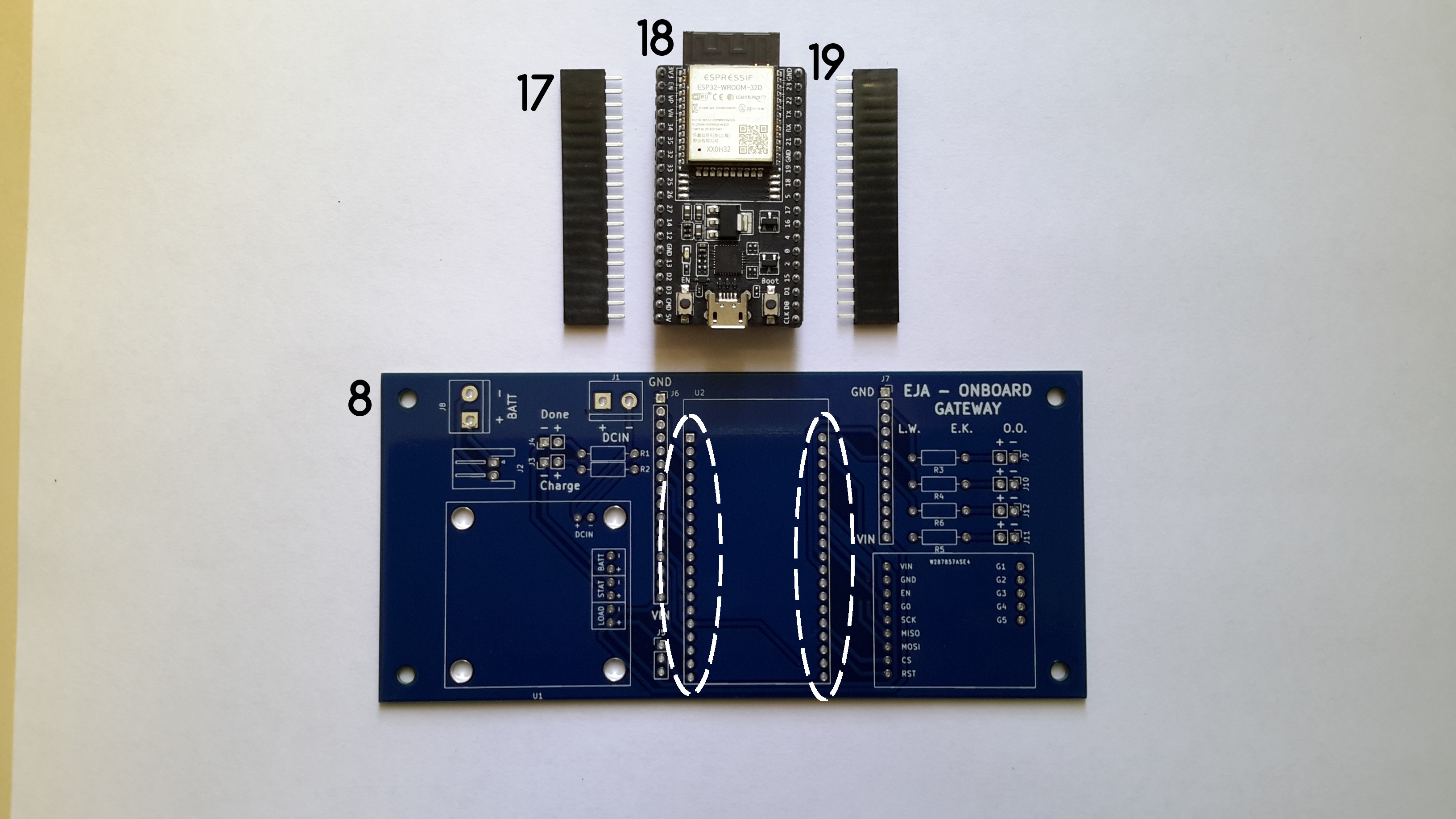
Once the female headers are soldered, the ESP32-DEVKITC-32D connects to the Onboard Gateway V1.0 through the headers.
b. Solder the female headers 22 and 23 used to connect the RFM95W LoRa Radio to the Onboard Gateway V1.0.
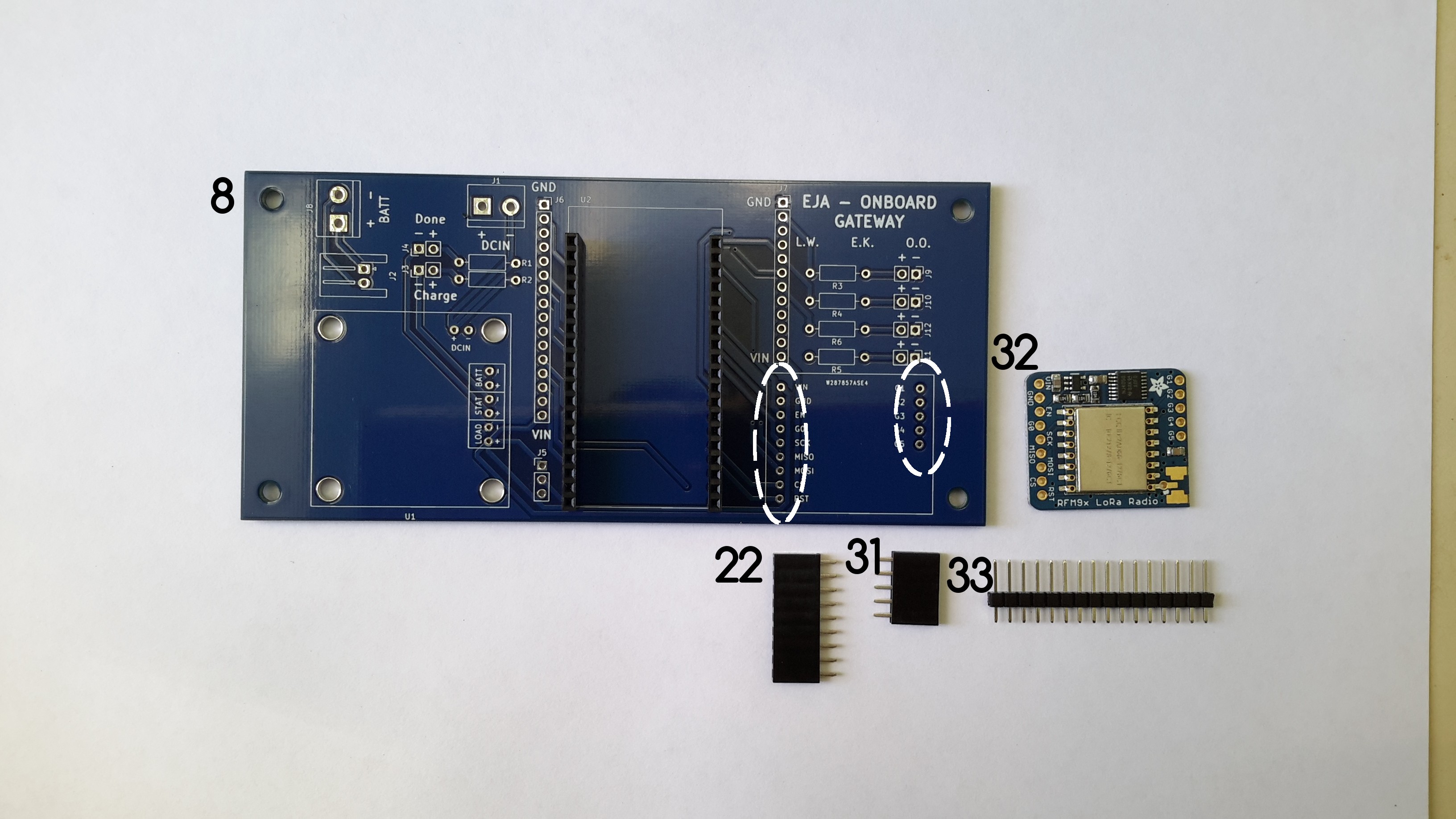
c. Solder the male headers 33 to the RFM95W LoRa Radio. To do that it is necessary to cut a CONN HEADER VERT 9POS 2.54MM and a CONN HEADER VERT 5POS 2.54MM from the component 33. Once the female headers are soldered, the RFM95W LoRa Radio connects to the Onboard Gateway V1.0 through the headers.
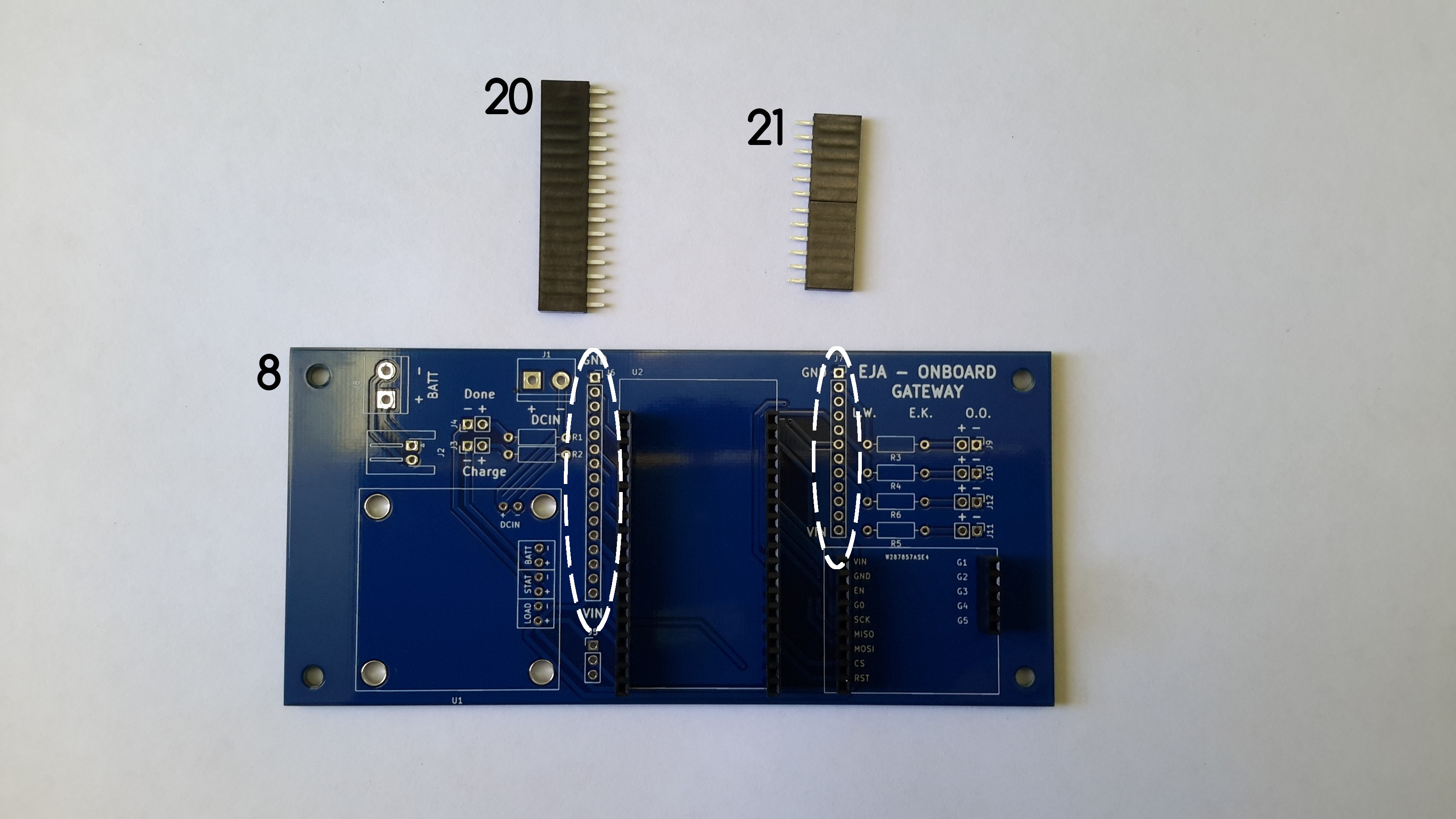
d. Solder the female headers 20 and 21 to the Onboard Gateway V1.0.
e. Solder the female headers 5 and 14, used to connect the USB LiIon/LiPoly charger to the Onboard Gateway V1.0. After that it is important to solder the male headers 9 and 13 to the USB LiIon/LiPoly charger.
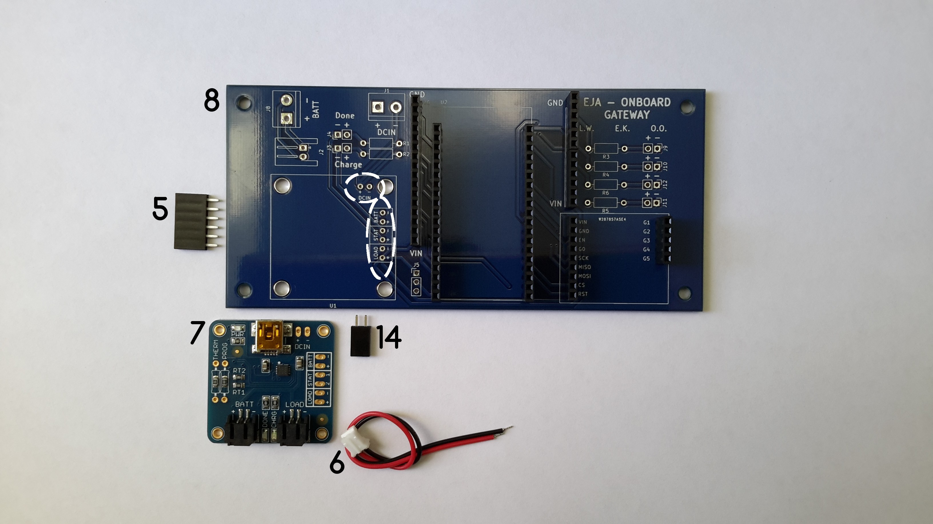
The USB LiIon/LiPoly charger connects to the Onboard Gateway V1.0 through the headers.
f. Solder the male headers and terminal block connectors.
Solder the male headers 3, 4, 23, 24, 25 and 25, used to connect the leds in the enclosure (through an additional cable). Solder the terminal blocks 1 and 12. Solder the 2POS Horizontal JST-XH connector (2)
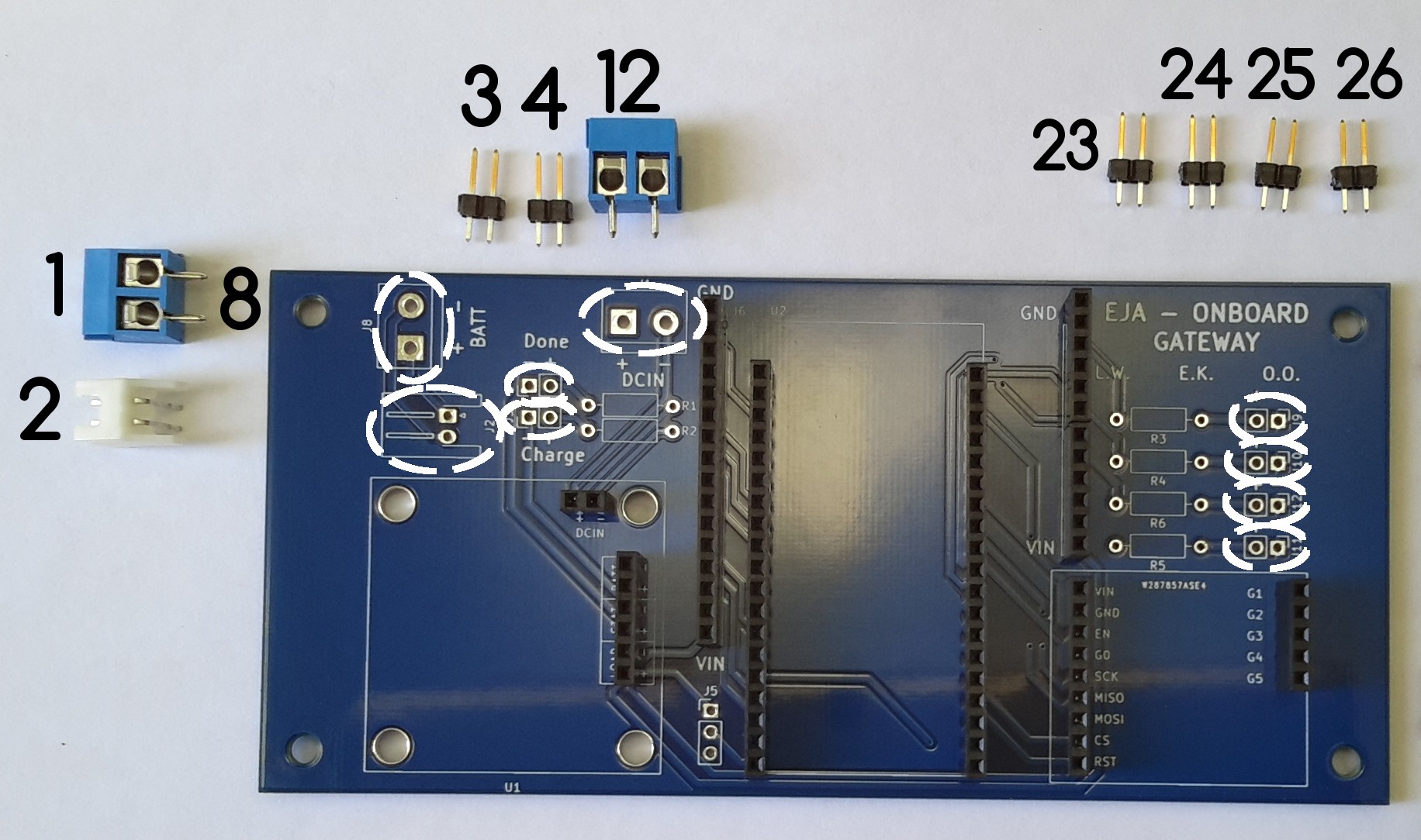
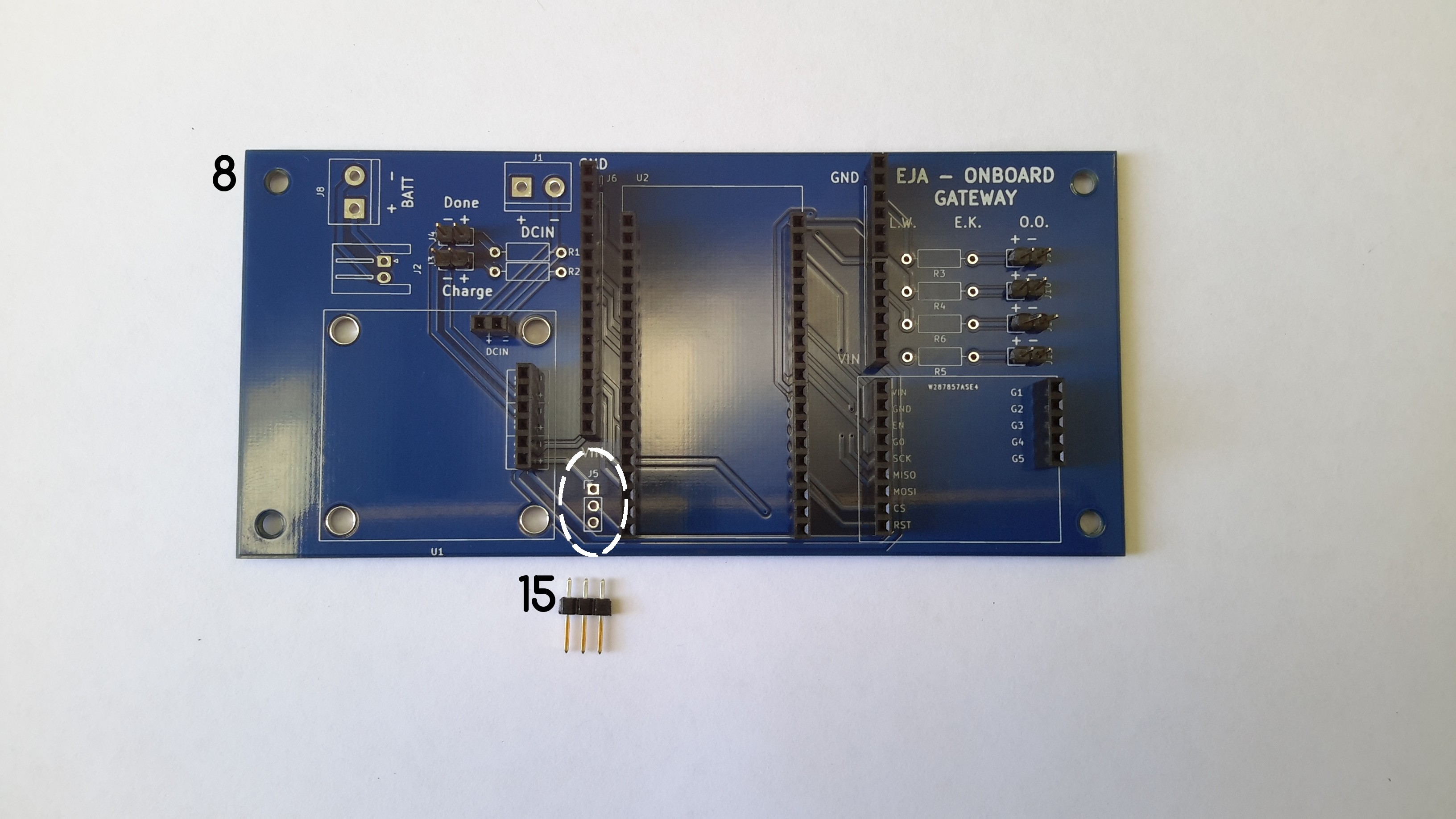
Solder the male header 15.
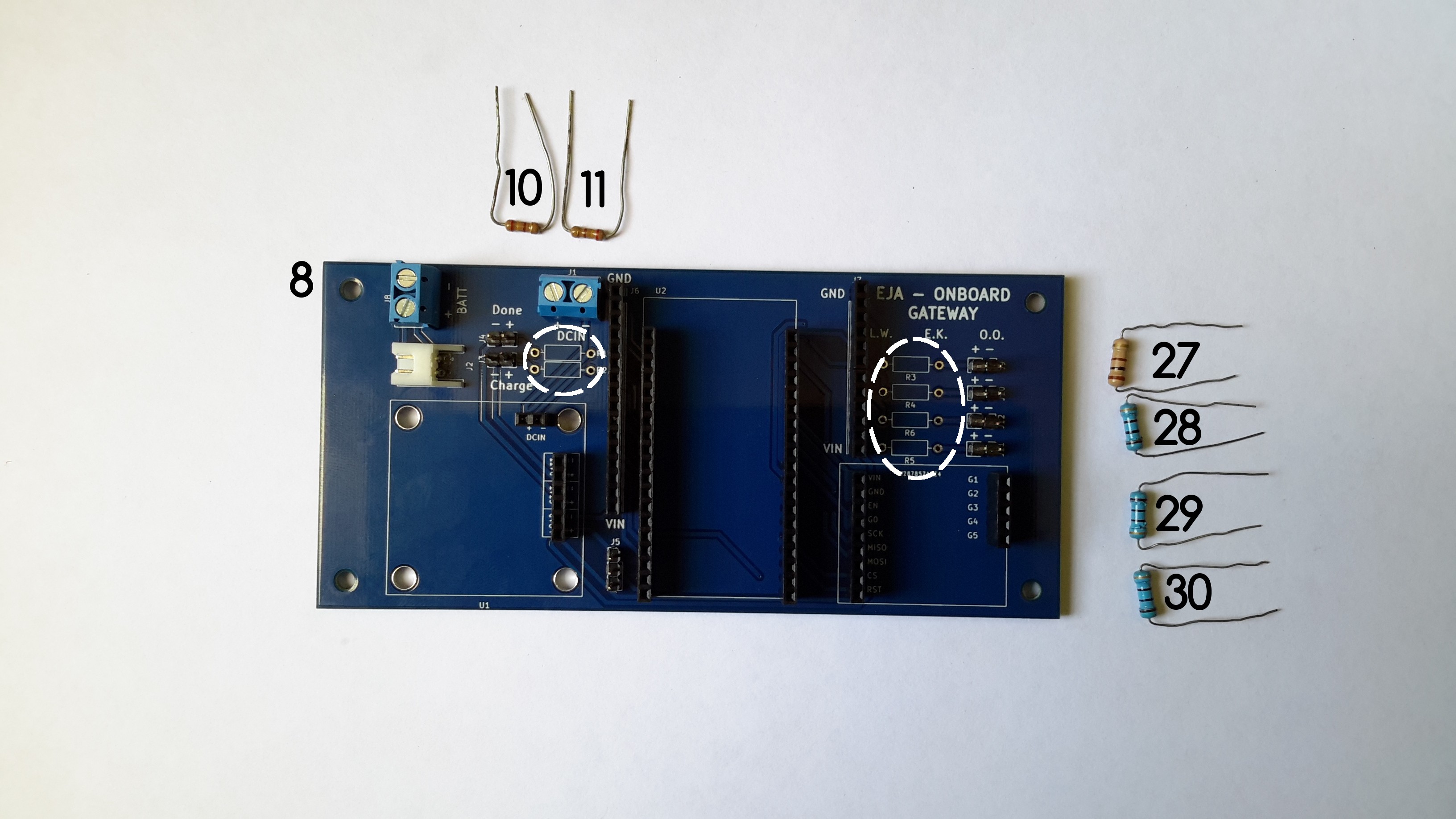
g. Solder the resistors used for the leds.
Discussions
Become a Hackaday.io Member
Create an account to leave a comment. Already have an account? Log In.