 Leonardo Ward
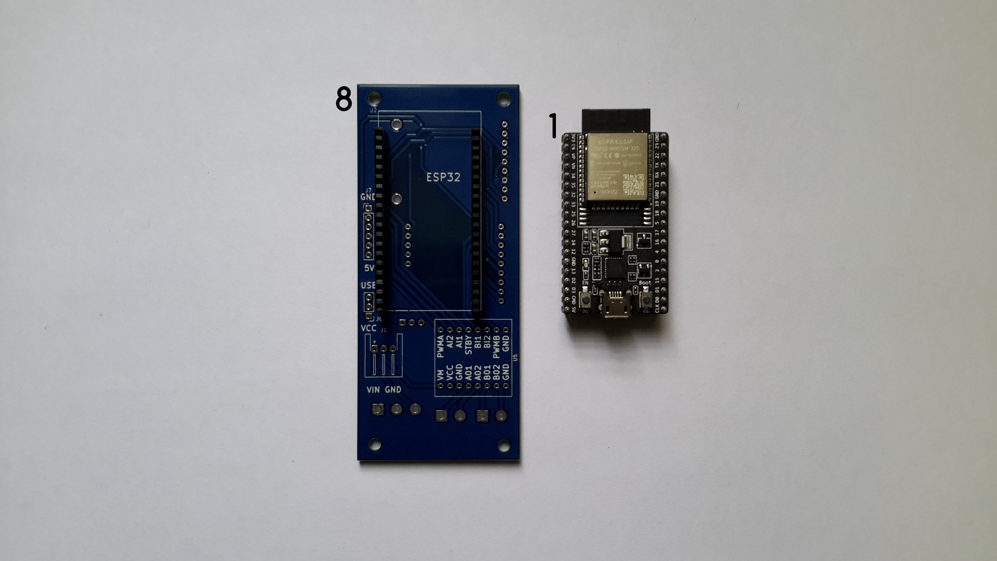
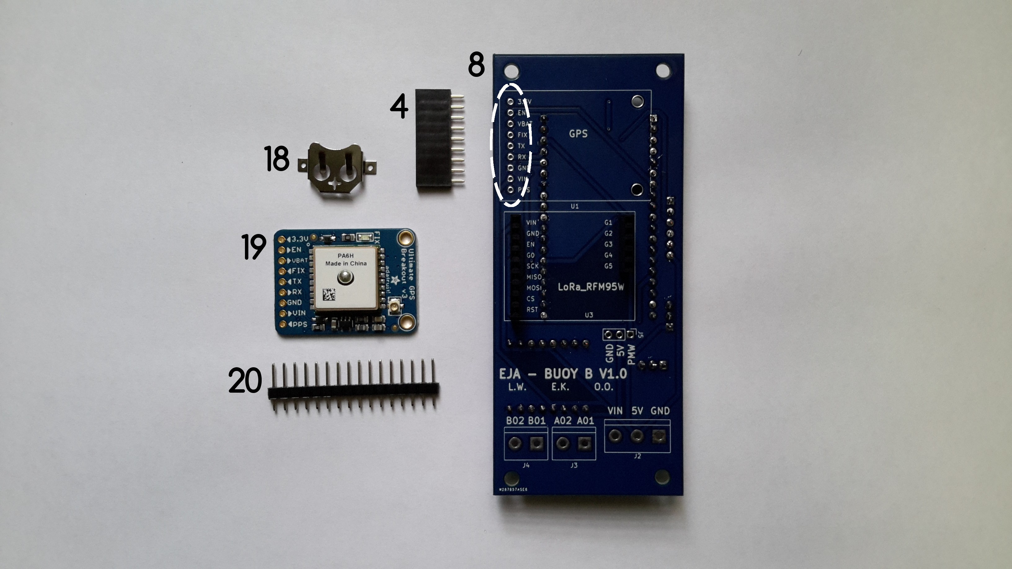
This log describes the recommended assembly instructions for the Buoy B V1.0 PCB. The following image shows all the required components, with an identification number that will be used in the log.

Components List:
- ESP32-DEVKITC-32D
- TB6612FNG MOTOR DRIVER BOARD
- CONN HDR 19POS 0.1 TIN PCB
- CONN HDR 9POS 0.1 GOLD PCB
- CONN HDR 9POS 0.1 GOLD PCB
- CONN HDR 8POS 0.1 TIN PCB
- CONN HDR 8POS 0.1 TIN PCB
- Buoy B V1.0
- CONN HDR 19POS 0.1 TIN PCB
- TERM BLK 2P SIDE ENT 5.08MM PCB
- TERM BLK 2P SIDE ENT 5.08MM PCB
- TERM BLK 3P SIDE ENT 5.08MM PCB
- CONN HDR 6POS 0.1 TIN PCB
- CONN HDR 5POS 0.1 GOLD PCB
- CONN HEADER VERT 3POS 2.54MM
- CONN HEADER VERT 3POS 2.54MM
- CONN HEADER R/A 3POS 2.5MM
- Coin cell holder (included in Adafruit Ultimate GPS)
- Adafruit Ultimate GPS
- CONN HDR 16POS 0.1 TIN PCB (included in Adafruit Ultimate GPS)
- RFM95W LoRa Radio
- CONN HEADER VERT 16POS 2.54MM (included in RFM95W LoRa Radio)
It is possible to solder the components in many different orders, I'll describe the one that I followed, it can used as a reference.
Instructions
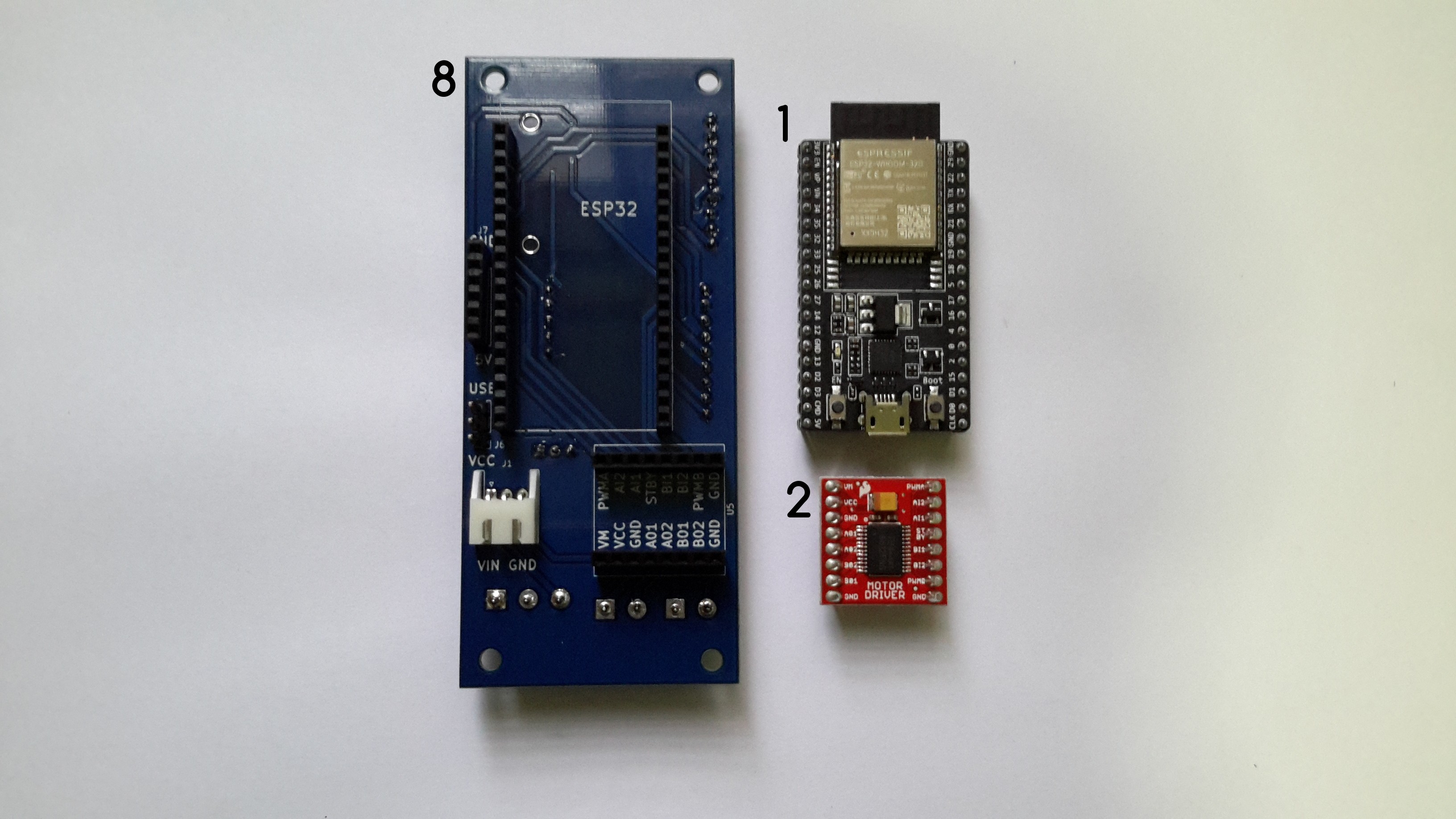
a.Solder the female headers 3 and 9 used to connect the ESP32-DEVKITC-32D to Buoy B V1.0.

Once the female headers are soldered, the ESP32-DEVKITC-32D connects to Buoy B V1.0 through the headers.
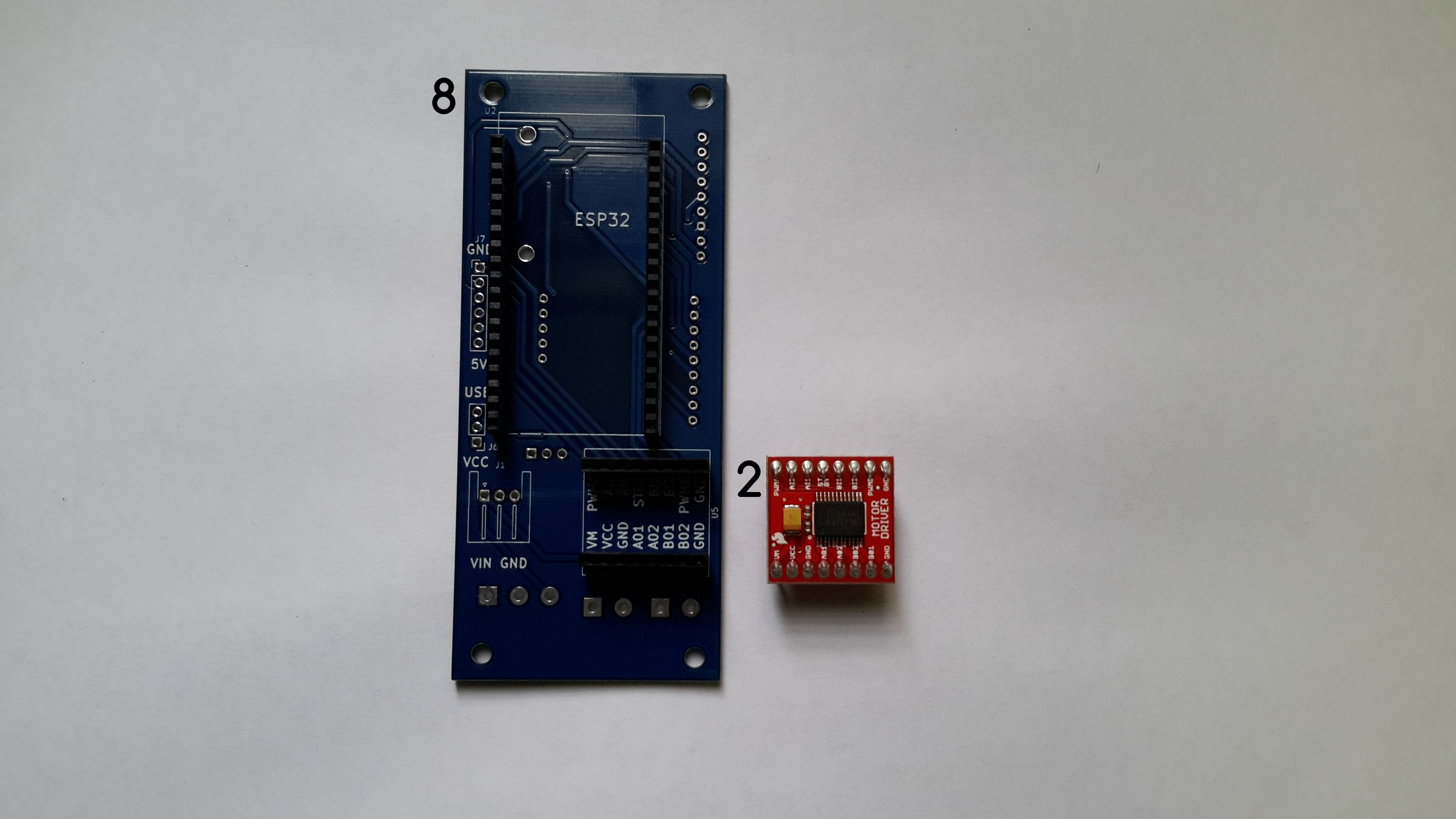
b.Solder the female headers 6 and 7 used to connect the TB6612FNG MOTOR DRIVER BOARD to Buoy B V1.0.
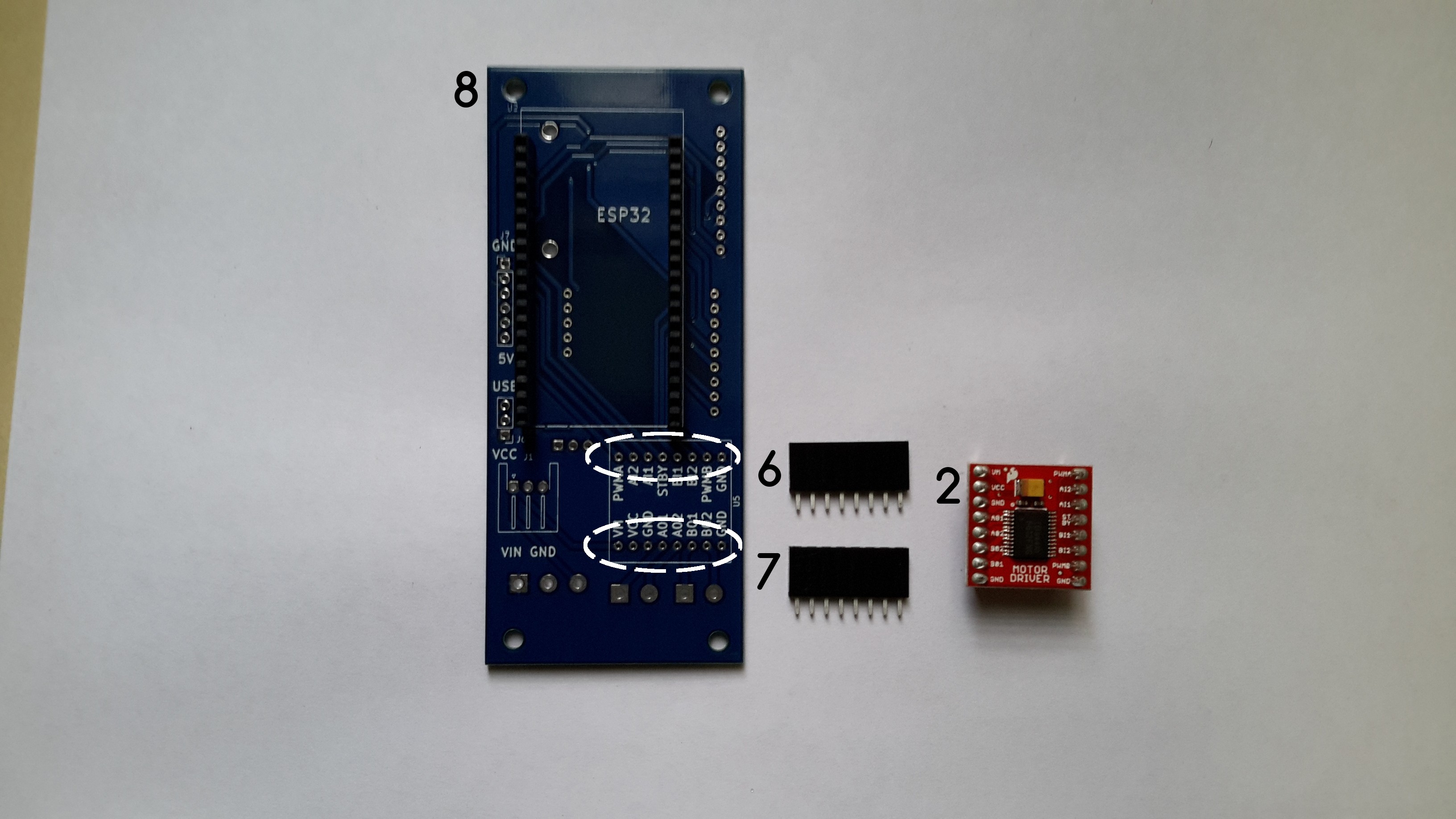
The TB6612FNG MOTOR DRIVER connects to Buoy B V1.0 using the headers.
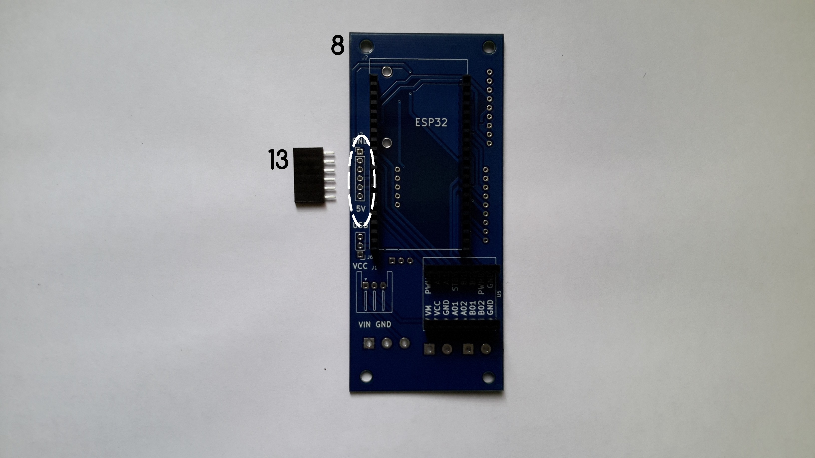
c. Solder the female header 13 to Buoy B V1.0.
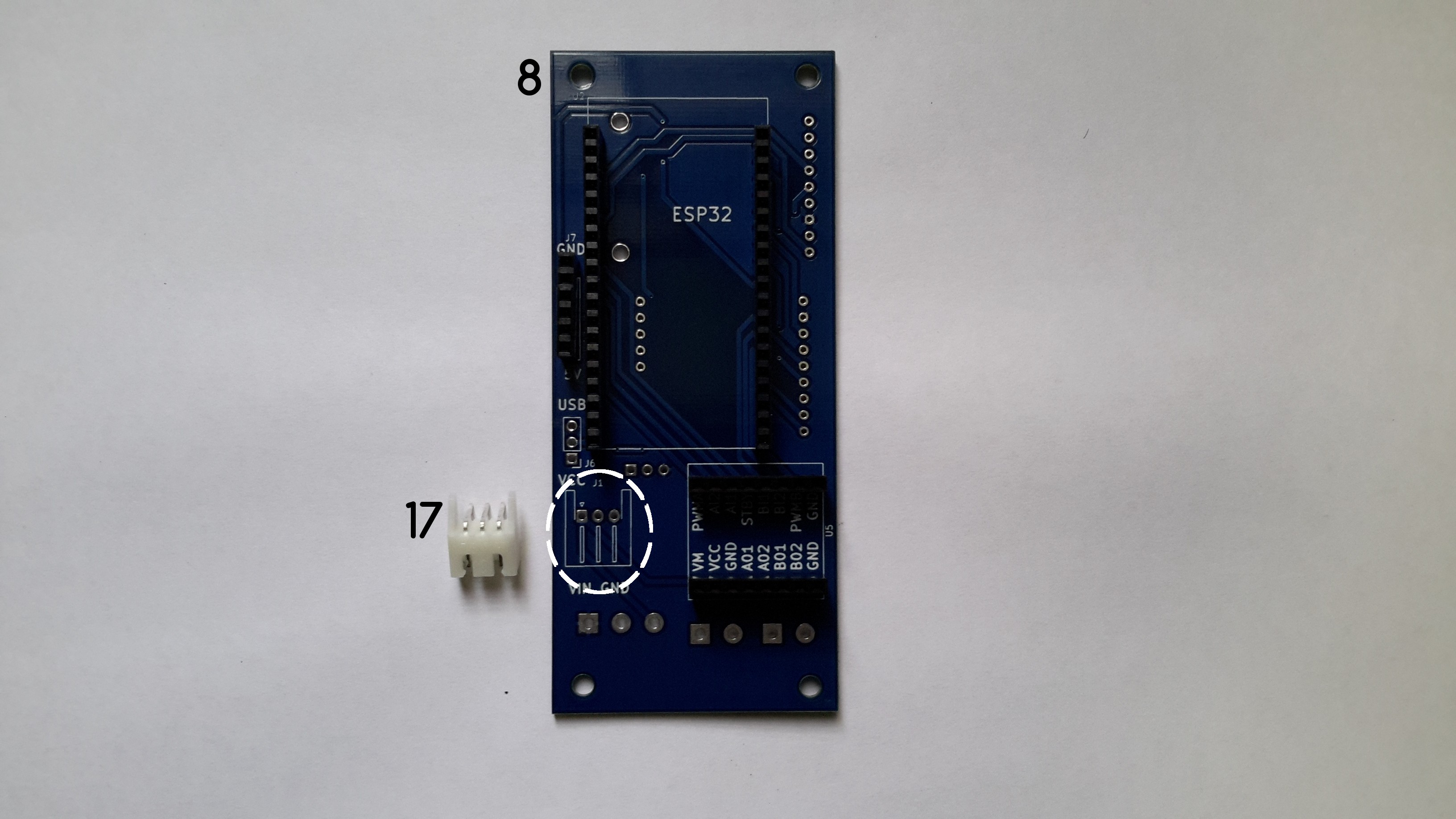
d. Solder the 3POS Horizontal JST-XH connector (17).
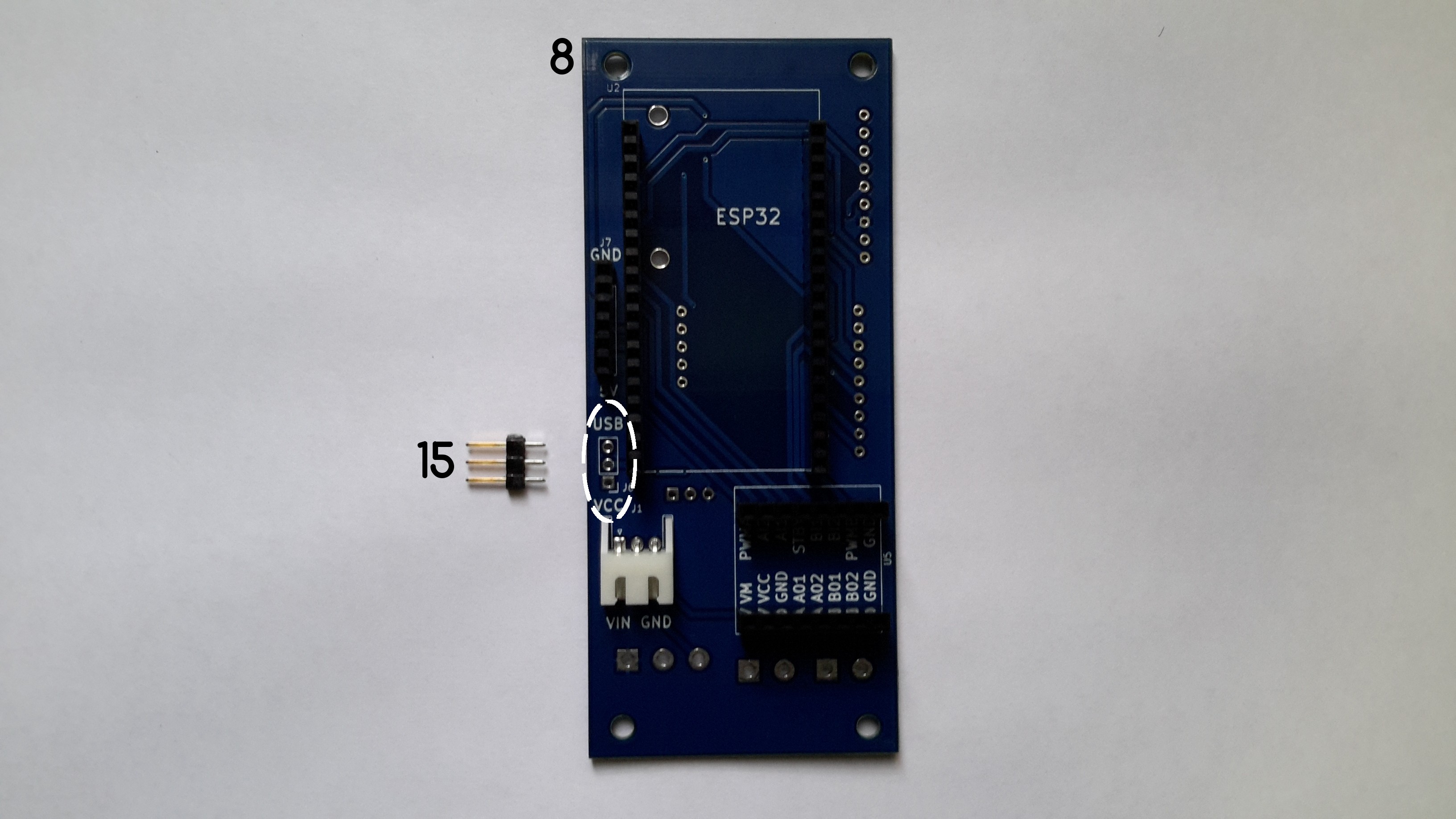
e. Solder the male header 15.
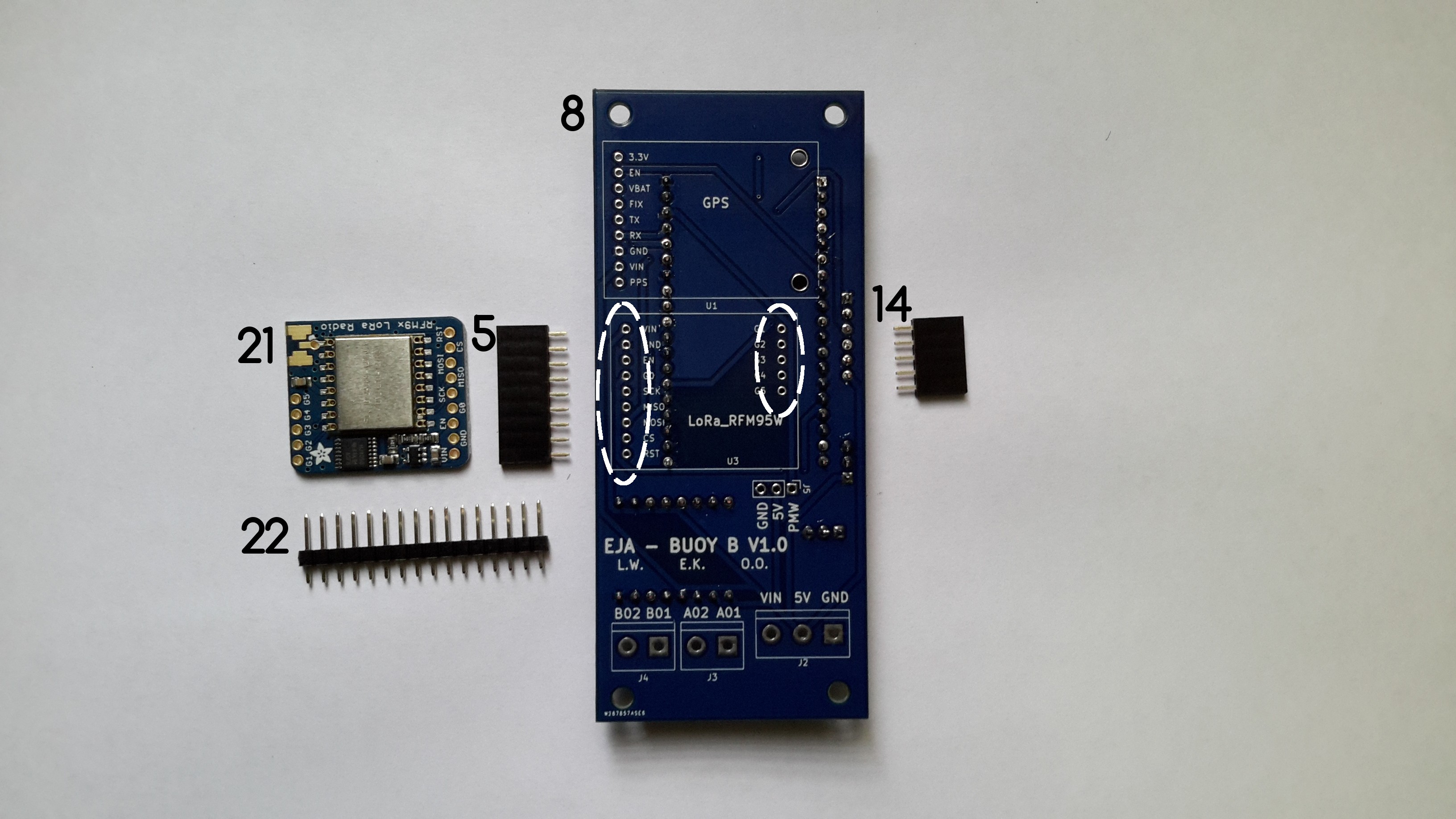
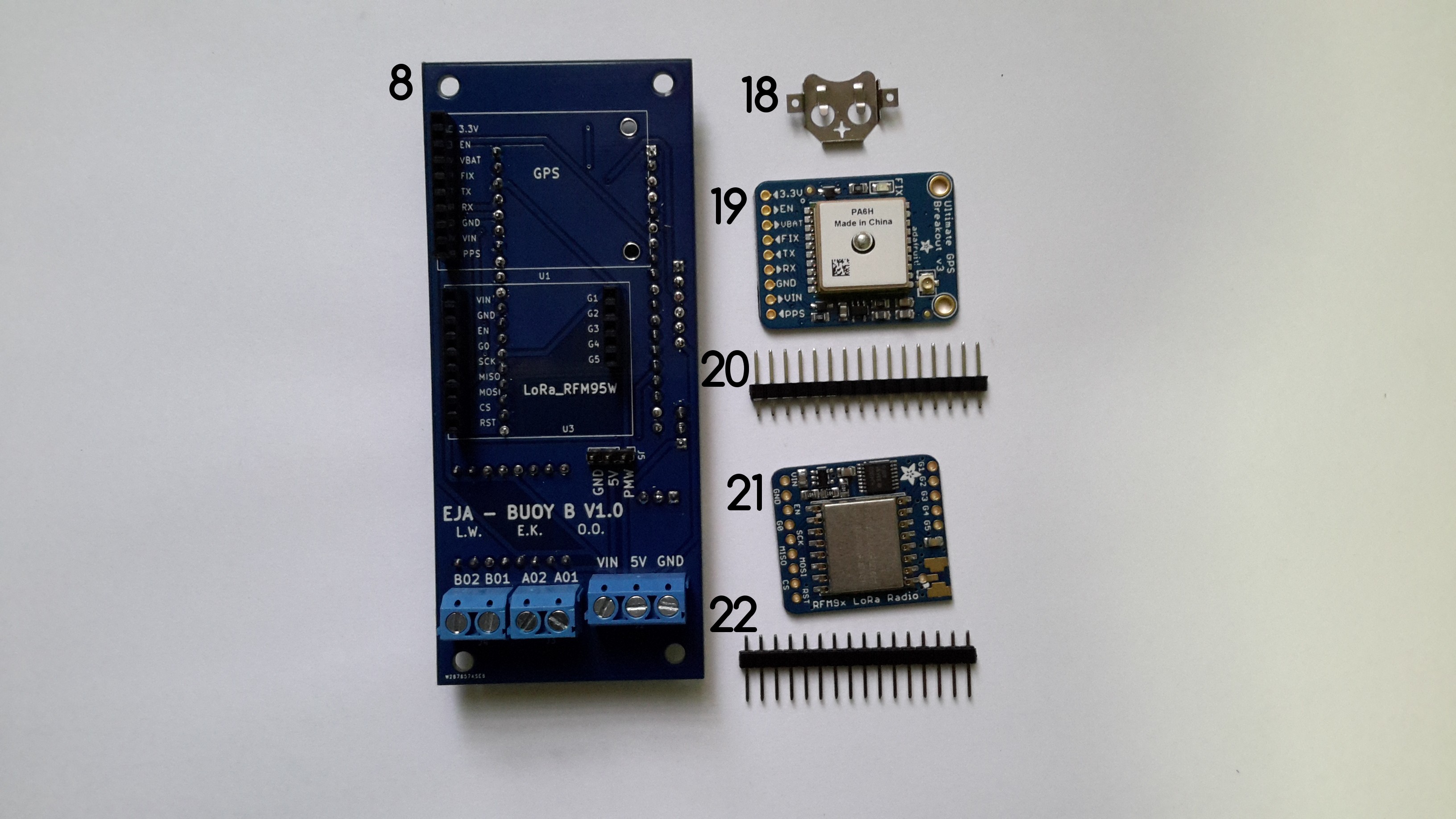
f. Solder the female headers 5 and 14 used to connect the RFM95W LoRa Radio to Buoy B V1.0.
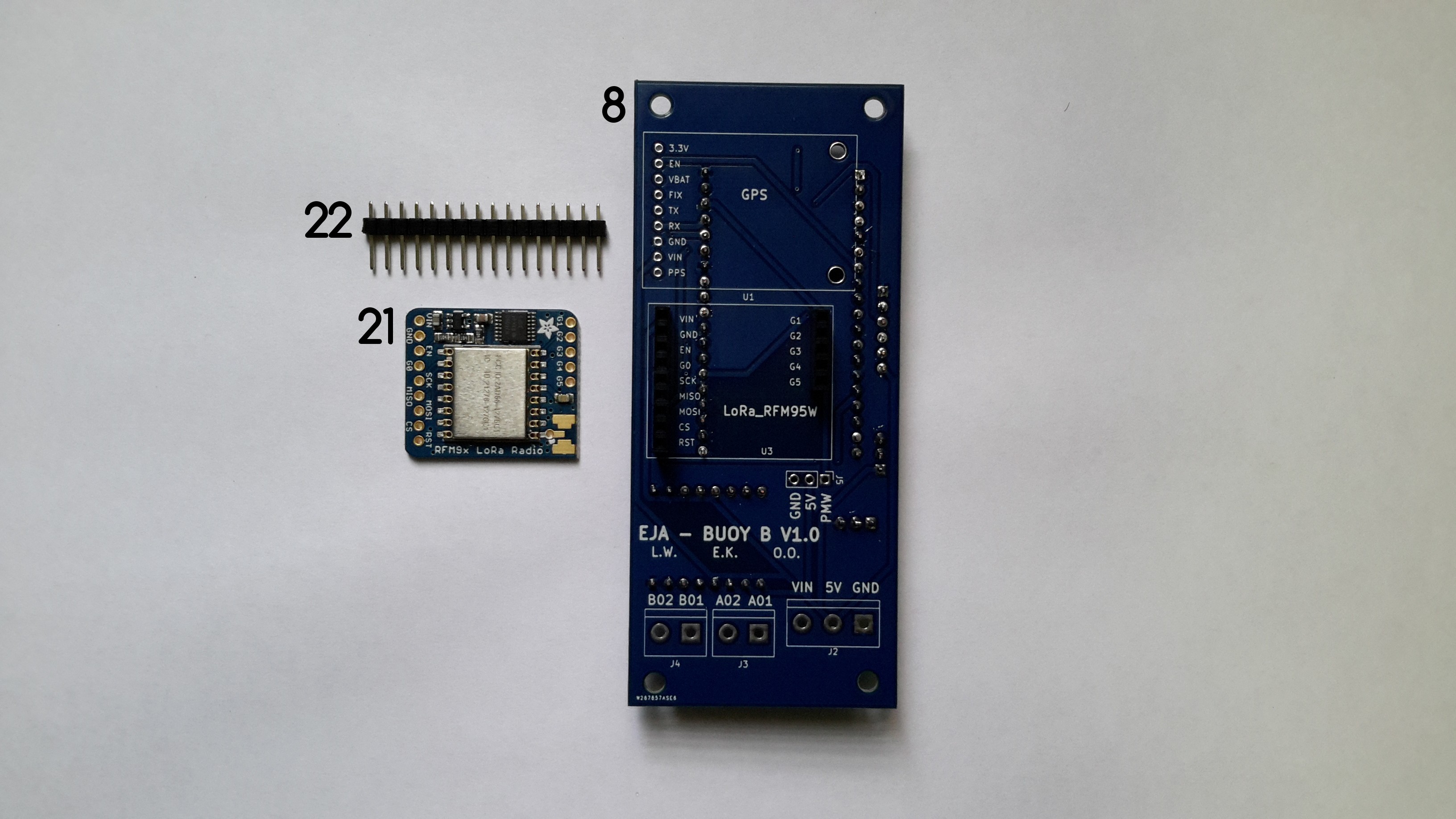
g. Solder the male headers 22 to the RFM95W LoRa Radio. To do that it is necessary to cut a CONN HEADER VERT 9POS 2.54MM and a CONN HEADER VERT 5POS 2.54MM from the component 22. The RFM95W LoRa Radio connects to Buoy B V1.0 through the headers.
h. Solder the female headers 4, used to connect the Adafruit Ultimate GPS to Buoy B V1.0. Solder the male headers 20 to the Adafruit Ultimate GPS. To do that it is necessary to cut a CONN HEADER VERT 9POS 2.54MM the component 20. The Adafruit Ultimate GPS connects to Buoy B V1.0 through the headers.
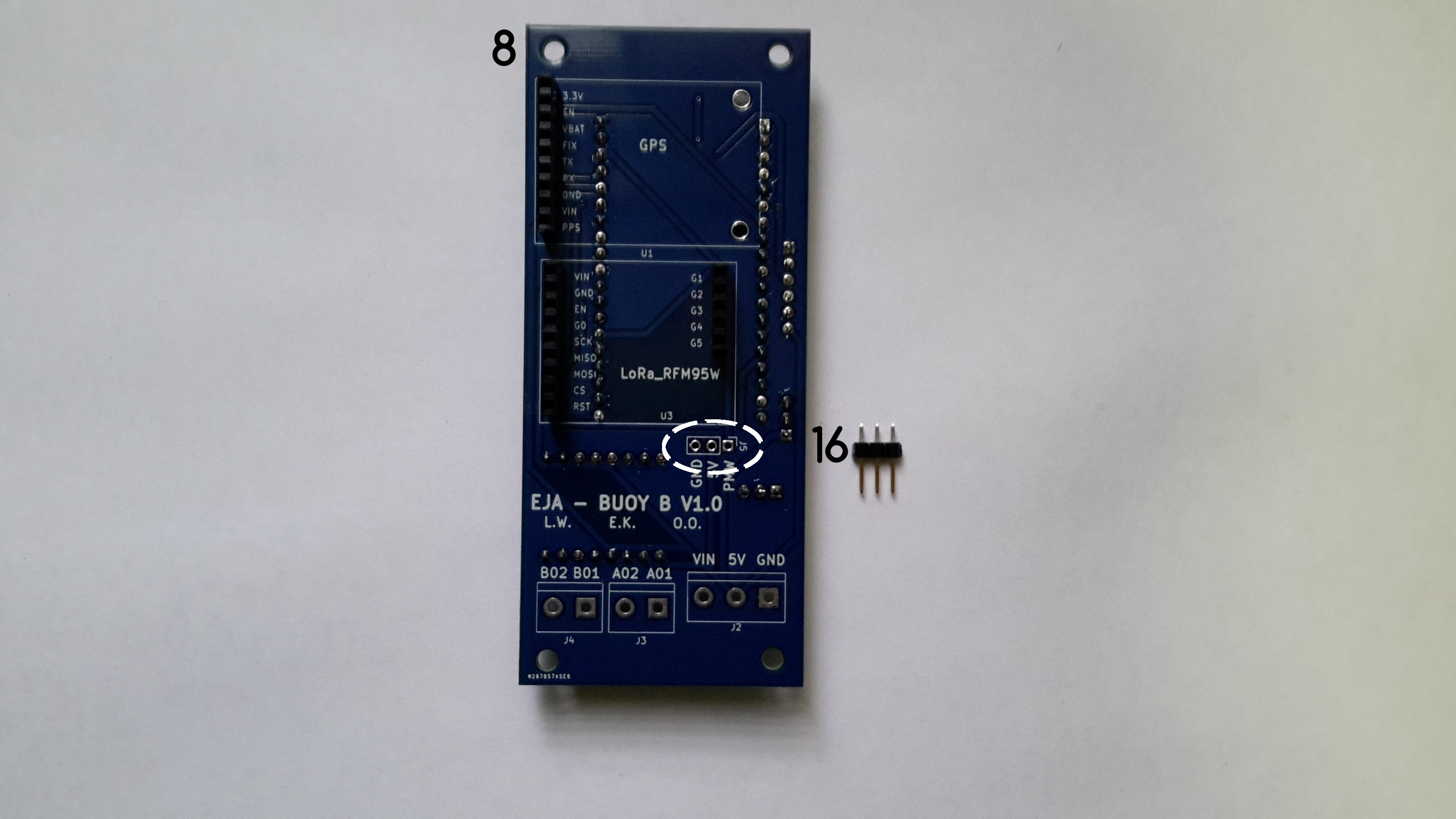
i. Solder the male connector 16 to Buoy B V1.0.
j. Solder the terminal blocks 10, 11 and 12 to Buoy B V1.0.
Front Layer and Back Layer
The modules connected to the front layer of Buoy B V1.0 are the ESP32-DEVKITC-32D and the TB6612FNG MOTOR DRIVER BOARD.
The modules connected to the back layer of Buoy B V1.0 are the Adafruit Ultimate GPS and the RFM95W LoRa Radio.
Discussions
Become a Hackaday.io Member
Create an account to leave a comment. Already have an account? Log In.