 Leonardo Ward
This log describes the recommended assembly instructions for the Buoy A V1.0 PCB. The following image shows all the required components, with an identification number that will be used in the log.
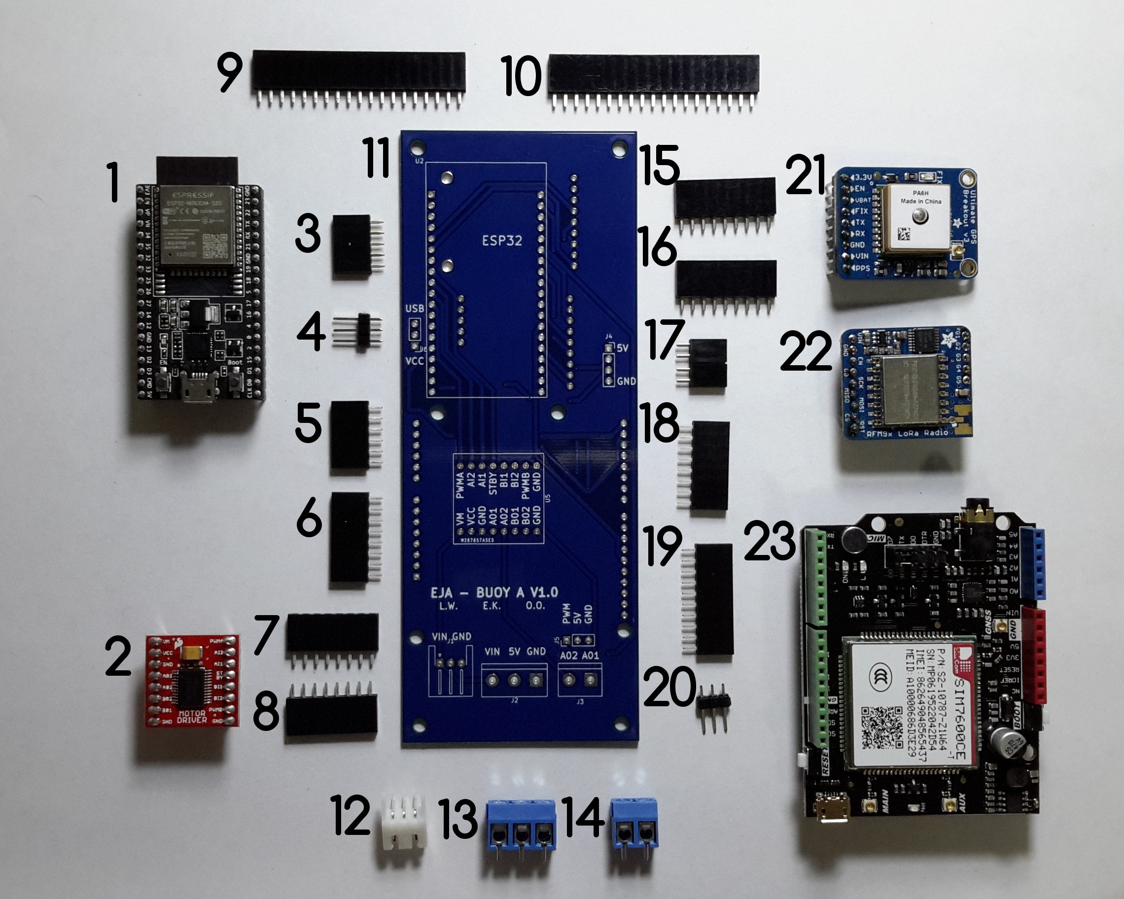
Components List:
- ESP32-DEVKITC-32D
- TB6612FNG MOTOR DRIVER BOARD
- CONN HDR 5POS 0.1 GOLD PCB
- CONN HEADER VERT 3POS 2.54MM
- CONN HDR 6POS 0.1 TIN PCB
- CONN HDR 8POS 0.1 TIN PCB
- CONN HDR 8POS 0.1 TIN PCB
- CONN HDR 8POS 0.1 TIN PCB
- CONN HDR 19POS 0.1 TIN PCB
- CONN HDR 19POS 0.1 TIN PCB
- Buoy A V1.0
- CONN HEADER R/A 3POS 2.5MM
- TERM BLK 3P SIDE ENT 5.08MM PCB
- TERM BLK 2P SIDE ENT 5.08MM PCB
- CONN HDR 9POS 0.1 GOLD PCB
- CONN HDR 9POS 0.1 GOLD PCB
- 2 CONN HDR 2POS 0.1 GOLD PCB
- CONN HDR 9POS 0.1 GOLD PCB
- CONN HDR 10POS 0.1 TIN PCB
- CONN HEADER VERT 3POS 2.54MM
- Adafruit Ultimate GPS
- RFM95W LoRa Radio
- SIM7600CE-T 4G(LTE) Arduino Shield
It is possible to solder the components in many different orders, I'll describe the one that I followed, it can used as a reference.
Instructions
a.Solder the female headers 9 and 10 used to connect the ESP32-DEVKITC-32D to Buoy A V1.0.
b.Solder the female headers 7 and 8 used to connect the TB6612FNG MOTOR DRIVER BOARD to Buoy A V1.0.
c. Solder the female header 17 to Buoy B V1.0.
d. Solder the 3POS Horizontal JST-XH connector (12).
e. Solder the male header 4.
f. Solder the female headers 3 and 16 used to connect the RFM95W LoRa Radio to Buoy A V1.0.
g. Solder the female headers 15, used to connect the Adafruit Ultimate GPS to Buoy A V1.0.
i. Solder the male connector 20 to Buoy A V1.0.
j.Solder the female headers 5, 6, 18 and 19 used to connect the SIM7600CE-T 4G(LTE) Arduino Shield to Buoy A V1.0.
k. Solder the terminal blocks 13 and 14 to Buoy A V1.0.
Discussions
Become a Hackaday.io Member
Create an account to leave a comment. Already have an account? Log In.