-
Manipulating audio sample data
07/10/2020 at 13:46 • 0 commentsLast time we figured out how sound works in code, so now we can get to the fun stuff and do some manipulation on that sound!
Now that we know that a sample is the amplitude, it was easy to figure out that by dividing or multiplying the value, you could make it louder or less loud. Now let's see what our sampler needs to be able to do.
When you use a sample on an Akai MPC1000, you can specify it's tuning during recording and manipulate the pitch after recording. On the MPC1000 this can sound quite grungy. I did not immediately know how pitch works in code, so I let it rest for moment and went on to re-watch some episodes of Community. My brain kept doing some thinking work while I was watching. I don't know if this will make sense to you, or if I'm even explaining this in a way that makes it clear, but let's have a shot. I figured when talking about music theory, for a certain tone to be an octave higher, the wave needs to be double the speed. So, when you want it be an octave lower, it needs to be half the speed.
Could it be really that simple?
It was already late, but ran to the basement where my 'lab' is to test my theory. I came up with this piece of code.
Sound[int(sPos++ * pitch)];In case you havent figured it out, this need to be in a loop where sPos increases the sample data index.
And you know what? To my big surprise this actually sound just like as it would on the MPC1000. There is a reason for that. I suspect the MPC1000 does not have a low-pass filter or any fancy algorithm correcting the aliasing that occurs when resampling the audio. So the artefacts that your hear are imperfections when modifying the length of the wave sample data.
Figure out how pitching works: CHECK.
If you have listened to my music, you will probably notice that I often like to use aliasing as an effect. Take this song for instance: 'https://open.spotify.com/album/5rpGsYSNGsEcHBqkMMOj1d?si=qn2PIBugQymtz5FKivAzqA', you can hear it very clearly in the vocal buildup in the middle of the song at 1:40.
With the newly gained knowledge about how and when aliasing occurs, we can create decimator effect (also often present in bit crusher style effects). This is what I came up with:
// decimator
float decimate = 1.0f;
if (decimate != 1) {
    int idx = int(int(sPos++ * decimate) / decimate);
    nLevel = Sound[int(idx * pitch)];
}
Now I'm not going to explain this in detail, just have a look at it, and try to figure it out knowing that 'Sound' is the signed 16-bit sample data, and nLevel is a signed short (or in other words a 16-bit signed int) that is going to be sent to the audio device's output. If you use a value of 0.1f for decimate, you will get a really low-fi gritty sound. just the way I like it.
Talking about bit crushing, how to approach that? Simple, by removing bits like this:
// bit reduction
int bits = 9;
nLevel = nLevel >> bits;
nLevel = nLevel << bits;
But on the MPC1000 the effect is called 'Bit Grunger', and does not sound like the bit reduction technique like in the code above. Instead, I think that they drive the sound by compressing the quiet parts, so that it fits into the new bitdepth. Think of it like rescaling the wave so it fits in the newly specified bit depth. Our code above just throws the bottom part away, but the code below adds some 'drive' to the sound.
// drive
float depth = 0;
if (depth > 0) {
    nLevel = 32767 * (tanh((float(nLevel)/32767)*depth));
}
If you do the driving part before the bit reduction, it will sound more like the 'Bit Grunger' effect on the MPC1000. By the way at this point I would like to thank Heikki Rasilo for helping me out with the math part of the drive. I did not even know what a tangent function was, and couldn't have done it without him. You know; I suck at math. In high school I even had extra after school classes for algebra, but it just didn't work. I failed maths that year, and went on to the lower grade wood workshop education course. But that said, I do have to take full credit for the pitching, decimator and bit reduction, even though it's pretty insignificant I'm pretty proud of my small accomplishment there.
Last thing I want to show you in this log is pitch shifting. Pitching also changes the playback speed. If you pitch a vocal down by an octave, it will take twice as long to playback from start to end. If you want to change the pitch but remain the timing, you can do that using fancy algorithms. But I just was toying with my own quick and dirty technique. It introduces some clicking at some points, but it'll do for now, it's just proof of concept.
// shift
//   we could add some sort af crossfading to minimize clicking artifacts
if (pitch != 1 && shift) {
    int size = 128 * 32; // a very small sample buffer such as 4 will result in a decimation effect too
    int mult = sPos / size;
    int offset = size * mult;
    int idx = int(offset + ((sPos - offset) * pitch));
    nLevel = Sound[idx] * gain;
}
What the code does is basically chop the sound up into very small parts, and just repeat or throw away these little parts to fit the original length of the sound when pitching.
I also tried to see if we could do some EQ on the sound, and found this handy class: 'https://www.kvraudio.com/forum/viewtopic.php?t=521184'. I am by no means capable of making that myself, so I'm going to kindly borrow it :-). Thanks to 'malcolm20' for writing it. He got the formulas from some kind of audio cookbook called the RBJ Cookbook. In this cookbook, I saw that there where also formulas for more types of parametric filters, so maybe someone with better math skills could help me out with that. We'll see what we need in the future, but for now I can do some early bench marking to see what the Pi is capable of. I didn't really have an idea of the polyphony. Well I did some quick tests, and a single core allows me to have 48 voices (mono) playing simultaneously, while gaining, pitching, EQing and mixing samples without drops or glitches. Also, all the code above relies on doing floating point operations, and these are expensive. So I can imagine a lot of optimisation could be done by people who know more about this kind of stuff. These are still very early days, but it at least we know that it's not just 1 voices, but a lot more. We have 4 cores available to do stuff, so if we can make two cores 48 voices simultaneously, that would be awesome.
By the way, mixing samples is also something special. Because the correct way is actually to divide each sample by two, and the sum of it is correct. but that would mean that when one of the sounds is silent, the other would be only half as loud as it should be. That is not the way our perception works. There is in fact a trick to do that, and for 16-bit signed integers we could do this:
MixSamples(TYPE a, TYPE b) {
    //source: http://atastypixel.com/blog/how-to-mix-audio-samples-properly-on-ios/
    return
        // If both samples are negative, mixed signal must have an amplitude between the lesser of A and B, and the minimum permissible negative amplitude
        a < 0 && b < 0 ?
            ((TYPE)a + (TYPE)b) - (((TYPE)a * (TYPE)b)/(-32768)) :

        // If both samples are positive, mixed signal must have an amplitude between the greater of A and B, and the maximum permissible positive amplitude
        ( a > 0 && b > 0 ?
             ((TYPE)a + (TYPE)b) - (((TYPE)a * (TYPE)b)/32768)

        // If samples are on opposite sides of the 0-crossing, mixed signal should reflect that samples cancel each other out somewhat
        :
            a + b);
}
I tried many different fomulas I found on the internet, but the one above was the one that works the best. Still, some clipping can occur, so if anybody wants to pitch in, feel free!
Currently I'm working on implementing a mixer, and a UI working on independent cores. I have received the Raspberry Pi 7inch touchscreen display, and am working with that. But I like where this is going already! I also ordered a couple of Audio Injector Octo sound cards that work over i2s. There is another user on hackaday.io that already wrote a lot of useful code using these that I'm going to have a look at. You can find the project here: 'https://hackaday.io/project/165696-rpi-bare-metal-vguitar-rig/log/165126-first-ui-and-bare-metal-multi-core'. Thanks Patrick, love your work, and it's going to help me a lot!
-
Finding out how sound works in code
07/08/2020 at 11:14 • 0 commentsLast time we set up the compiler environment. I'm using it extensively now and works great. I only had a few times where the bootloader did not start the image after sending it over serial (and then I had to reset it and send the image again, so no drama).
I decided to start out by using the '34-sounddevices' sample project, because it looks like it's really simple to modify it, and get it to play sound data instead of a 440hz tone.
So my idea is to add sound data to the project, so that I can patch it in to where the 440hz tone is fed into the buffer. I'm really in unfamiliar territory here, but have heard of the double buffering pattern. I think that's what the original author does here. We have an audio buffer of a fixed length, and then there is a loop that will fetch data from this buffer, and write parts of it to the audio device's output buffer. We are supposed to write data to the first buffer, so that the loop can write it to the second. The reason behind this is to prevent audio dropouts. Basically by having two audio buffers, we make sure that the strictly timed audio device always has data, even if the timing of the processing/generation code is not that strict. Audio is something that is very time sensitive. Much like a video plays at 30 frames per second, cd-quality audio (wow that's been a while since I called it that) needs 44100 samples per second (times two if you want stereo output).
If you're already experienced with how sound works in bits and bytes, I suggest you skip the rest of this log, as it really only explains the fundamentals, no advanced processing (yet).
Now let's talk about what a sample actually is. Before starting this project, I had a vague representation in my head of how a sample is stored in computer memory. But diving deeper into this, I picked up a few things.
So let's get it out of the way; sound consists out of waves. A wave goes up and down. Depending on how loud it is, the wave goes higher. But like I said, a wave goes up and down. When it goes down, it still goes louder. This is called the amplitude. It's an audio waves thing, if this sounds weird to you, I suggest you look up on information how sound reproduction works, like say how a speaker reproduces sound.
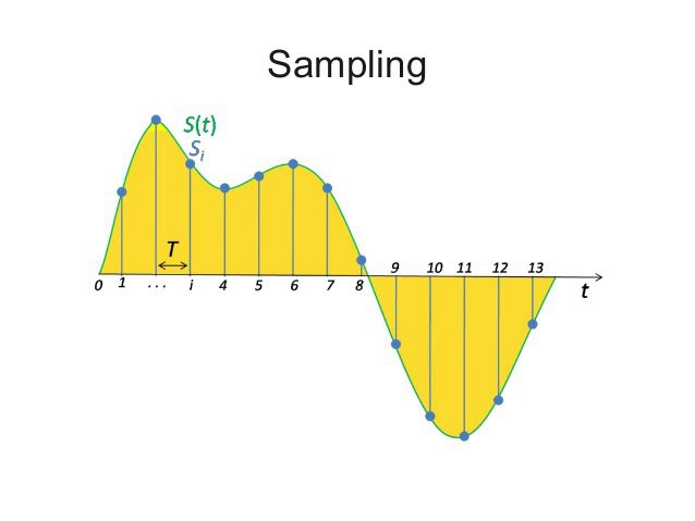
A computer does not store waves, it stores bits. So, how can a computer then store a wave? By taking samples from it. Samples are points in time where the amplitude of a wave are measured. And for cd-quality audio, for every second 44100 points are measured.
There is a good image on wikipedia that illustrates this, every point on the wave is a sample:
![]()
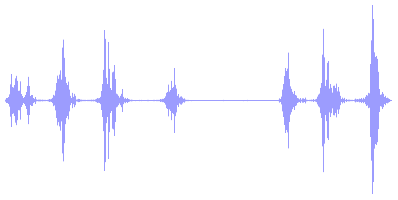
For the time being, assume we're talking about 1 channel (so mono, not stereo). When your audio is stored as 8-bit, your computer offers you an array of 44100 bytes for each second of audio that represent the loudness of those parts of the wave. The bytes represent time sequentially, so byte 22050 contains a sample of the wave at 0.5 seconds in time. So every byte is 1 sample. The midpoint of a wave is silence. In the illustration from wikipedia above, the midpoint is represented by the line in the middle. The image below illustrates this a little bit better because its shows you a longer waveform over time, you may say it's 'zoomed out' compared to the illustration from wikipedia above, which is heavily 'zoomed in'.
![]()
In 8-bit audio the midpoint is 127. So silence is represented by 127. That is ... when we are talking about 8-bit audio. For those of you who lived and played games in the MS DOS era, 8-bit audio just sounds yuck. CD-quality audio is 16-bit. And in 16-bit you have the choice to see your samples represented as a signed or unsigned integer. In case you wonder, a 'signed' integer is a number that can go below zero. Knowing that, when using a 16-bit signed integer, the highest amplitude (a.k.a. loudness) a sample can have is 32767 and -32767, and so 0 equals silence. On the other side, if audio is stored as a 'unsigned' 16-bit integer, the highest amplitude is 0 and 65535, where 32767 is the midpoint and equals silence. You see, the result is exactly the same, it's just a different way of storing the data. As a human, I like the signed representation, because that aligns with the way my brain thinks. Wave goes up: number is positive, wave goes down: number is negative, wave is center (so, complete silence): number is 0. Using signed integers for samples also makes doing math on them a lot easier. Spoiler alert: later on we'l discover that converting the signed integers to floating point data for processing is the ultimate way.
Now that we know this, we can start manipulating samples using maths! Yeeey! If you read the previous log, maybe you'll remember me saying that I suck at maths. That hasn't changed. I might even have a mild form of dyscalculia, who knows. That being said, expect calculation mistakes along the way on my part. Don't say I didn't warn you!
Let's see how we can apply that in practice. Suppose we have an 44100hz 16-bit audio buffer called 'Sound' filled with samples. We want to make the first two seconds less loud. We can do this by modifying the amplitude of the samples for the first two seconds by doing this:
for (int s=0; s<88200; s++) {
    Sound[s] *= 0.5;
}
If you know that there are 44100 samples in a second, then you know that two seconds worth of audio has 88200 samples.
And so our journey has begon in manipulating audio. In the next log I hope to share some project code with you. When learning the information above myself, I already created some filter algorithms that mimic the sound of the mpc1000, so I'm pretty excited to share this with you!
-
Setting up our build environment
07/04/2020 at 14:58 • 0 comments![]()
I'm running macOS. I prefer that over Linux and Windows. I have worked a few years in IT infrastructure, and while my experience with Linux may not be equal to the veterans; I think the Linux ecosystem often gets in the way if you just want to get things done quickly without having to tinker too much. Windows is just.. well let's say uninspiring. I hate Windows style paths. Despite having years of scripting experience with Batch, I'm not looking forward to using it again and Powershell is just an abomination (to me). macOS has a great balance, despite most likely being 'evil', but I must be honest and say that I don't really care and just want to get thins done. Politics aside, let's set up the compiler environment on macOS Catalina.
Contents
Installing the build tools
Preparing the compilation workflow
Cloning the Circle repository
Setting up the project, and pre-building the framework binaries
Serial bootlader
Monitoring the serial port
Soldering a reset switch
That's it!
Installing the build tools
You'll need to install Brew. Get that done first!
First I installed the 64 bit arm compiler from here:
brew tap SergioBenitez/osxct
brew install aarch64-none-elf
brew install qemu
But, it seems that the 'g++' variant is missing for building c++ code, so I don't think this is a real requirement but had it installed anyway because of a previous experiment with bare metal programming on the Pi 3 B+.
This one has the compiler that the build scripts of Circle use, so we'll need this:
brew tap ArmMbed/homebrew-formulae
brew install arm-none-eabi-gcc
We need make for building, and if you have the xcode commandline tools installed, make comes with it. But the problem is that the make version is too old for building Circle, so we need to install a newer version.
brew install makeAfter installing, you might have a conflict if make was already on the system and the newer version will be installed as 'gmake' instead of make. You can fix this by adding the new make binary to the path variable of your terminal. macOS Catalina now uses zshell, so you add it to your profile by modifying (or creating if it does not already exist) '~/.zprofile':
PATH="/usr/local/opt/make/libexec/gnubin:$PATH"After closing and reopening the terminal, executing 'make -v' will give you a version above 4.
Circle's bootloader build script uses wget to fetch some files from a git repo, and macOS has curl installed by default. So we need to add wget to our system.
brew install wgetWe'll also need the python serial module for flashing our circle binary to the Pi over serial. More on that later, but we'll need this:
pip3 install pyserial----
EDIT: Since then, Circle now has a better flasher that uses node.js, so the pyserial is no longer a requirement if your using the new flashy. You need to specify this in the config.mk, which i will adapt to reflect the changes in this article. However, if you so desire, you can still use the old python based flasher. I think flashy is a real improvement.
You will need to use npm to resolve the dependencies:
cd tools/flashy
npm install
----
Preparing the compilation workflow
Cloning the circle repository
We'll start of by cloning the Circle repo from GitHub.
git clone https://github.com/rsta2/circleSetting up the project, and pre-building the framework binaries
First we have to modify the 'Rules.mk' file in the project root. We'll have to change the RASPPI version to the board we're using (for me that is 4), and we'll keep the 32bit architecture. If we want 64bit, we'll need to find the right compiler, but I'm not going to do that. For now, 32bit will be fine.
AARCH     ?= 32
RASPPI     ?= 4
After doing that, we can start and build the framework binaries. Execute in the project root:
./makeall clean
./makeall
Depending on your computer, this will take a few seconds or cloud take a few minutes.
Serial Bootloader
Circle is already well developed, and comes with easy to use build scripts. Normally, when you want to use your custom kernel, you'll build it, and copy files to the microsd card, and insert it into your Pi. This will get very old soon, so we'll prepare a workflow for flashing the kernel over serial. This will allow us to upload a new kernel every time we reboot the pi.
You'll need a usb-serial debug cable. I bought this one: Serial Debug Cable AliExpress
Once you have received the debug cable, plug it into you mac and find out which device it is. I don't really know what the official way is, but I found it by executing:
ls /dev/tty.*You'll get a list of possible candidates (I don't think there should be a lot of results, but it depends on your computer configuration and connected peripherals of coarse). Mine appears to be '/dev/tty.usbserial-31170'.
We'll need to create a file in the project called 'Config.mk', and add the following contents:
SERIALPORT = /dev/tty.usbserial-31170
FLASHBAUD = 921600
USERBAUD = 115200

USEFLASHY = 1
REBOOTMAGIC = reboot-debug-flash
#FLASHYFLAGS = <other command="" line="" args="" for="" the="" flashy="" script=""></other>
Replace the 'SERIALPORT' value with your device path.
The 'FLASHBAUD' variable may also need to be adjusted for your specific usb-serial cable, but the one I use can handle this speed. It's possible you'll have to experiment with different speeds for your cable, you can find out more about this in the Circle docs folder.
As far as I know, the 'USERBAUD' will be used for the communication speed, but I've seen a lot of examples where the speed is hard coded to 115200 so don't really know about that yet.
---
EDIT: Note that we added the USEFLASHY entries to use the new node.js based flasher.
---
After that, we can build the serial bootloader. It's important to create the 'Config.mk' file before building the bootloader, because it will use the 'FLASHBAUD' variable and bake the speed into the bootloader.
cd boot
make
Now we need to create a file in the boot folder called 'cmdline.txt', you can find out more about it in the Circle doc folder. Make sure this file contains:
logdev=ttyS1
This will make the logger output to your serial terminal. If you do not add this, the logger will print to the screen attached to the Pi.
We are now ready preparing the bootlader. This bootlader will be placed on the microsd card, and we will only have to do this once.
----
EDIT: I forgot to document one important step! You need to build Circle's Serial Bootlader kernel image.
cd tools/bootloader
make
Then you can copy the kernel images to the boot folder. Also, for the pi 4, you need to build the armstub as outlined in the Circle documentation:
cd boot
make armstub
Now you are ready to copy the contents of the boot folder to the SD Card.
----
Copy the contents of the boot folder to an SD card. The 'config.txt' is only required when targetting aarch64, which we are currently not doing because of the missing compiler, so DO NOT COPY IT OVER TO THE MICROSD CARD or it will not work.
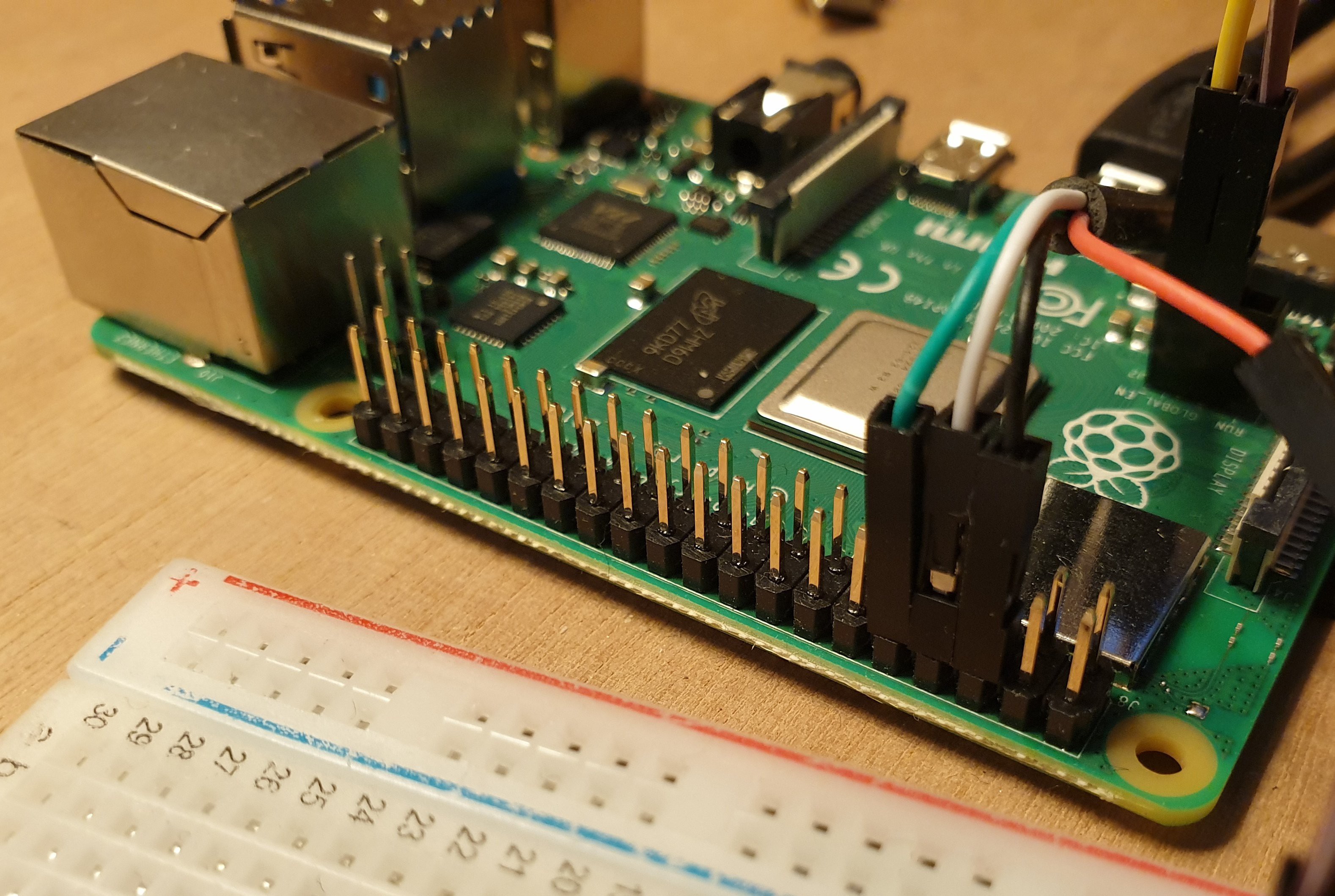
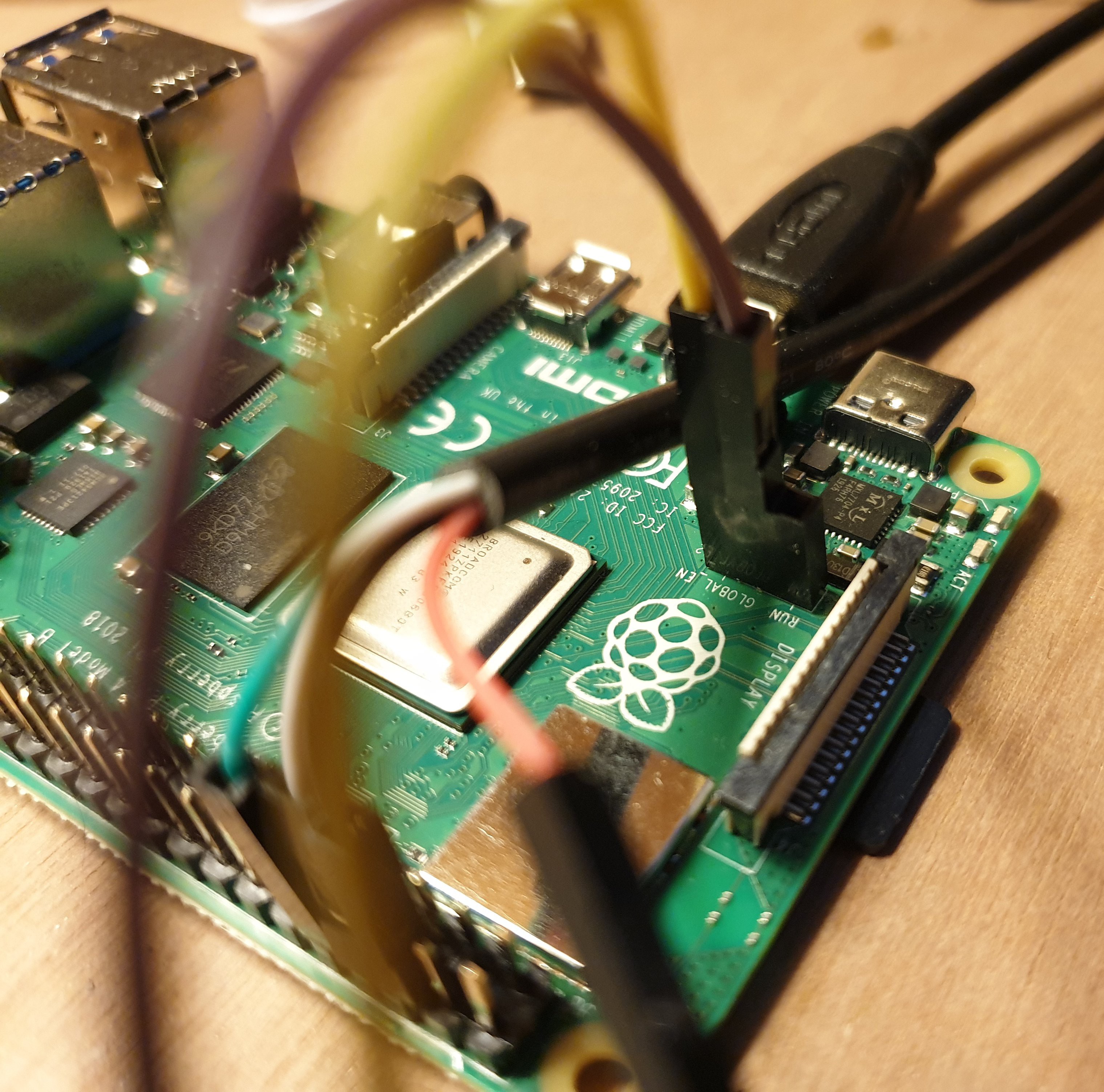
Connect the usb serial cable to the pi using the correct pins. My serial cable (PL2303TA USB to TTL Serial) has the following color coding: Red 5V, Black 0V (Ground), White RX, Green TX. Though I suspect my cable's documentation has white and green mixed up.
I connected the black cable to third pin on the first row, the white one to the fourth pin and the green one to the fifth pin.
![]()
Insert the microsd card, and power on the Pi.
When the screen shows the rainbow colors and the act led is off, it's ready to accept a bootloader from the serial port.
So let's build the very first example.
cd sample/01-gpiosimple
make flash
After the bootlader has been sent over to the Pi, it should blink the act led 10 times and reboot. You'll know it has worked.
Monitoring the serial port
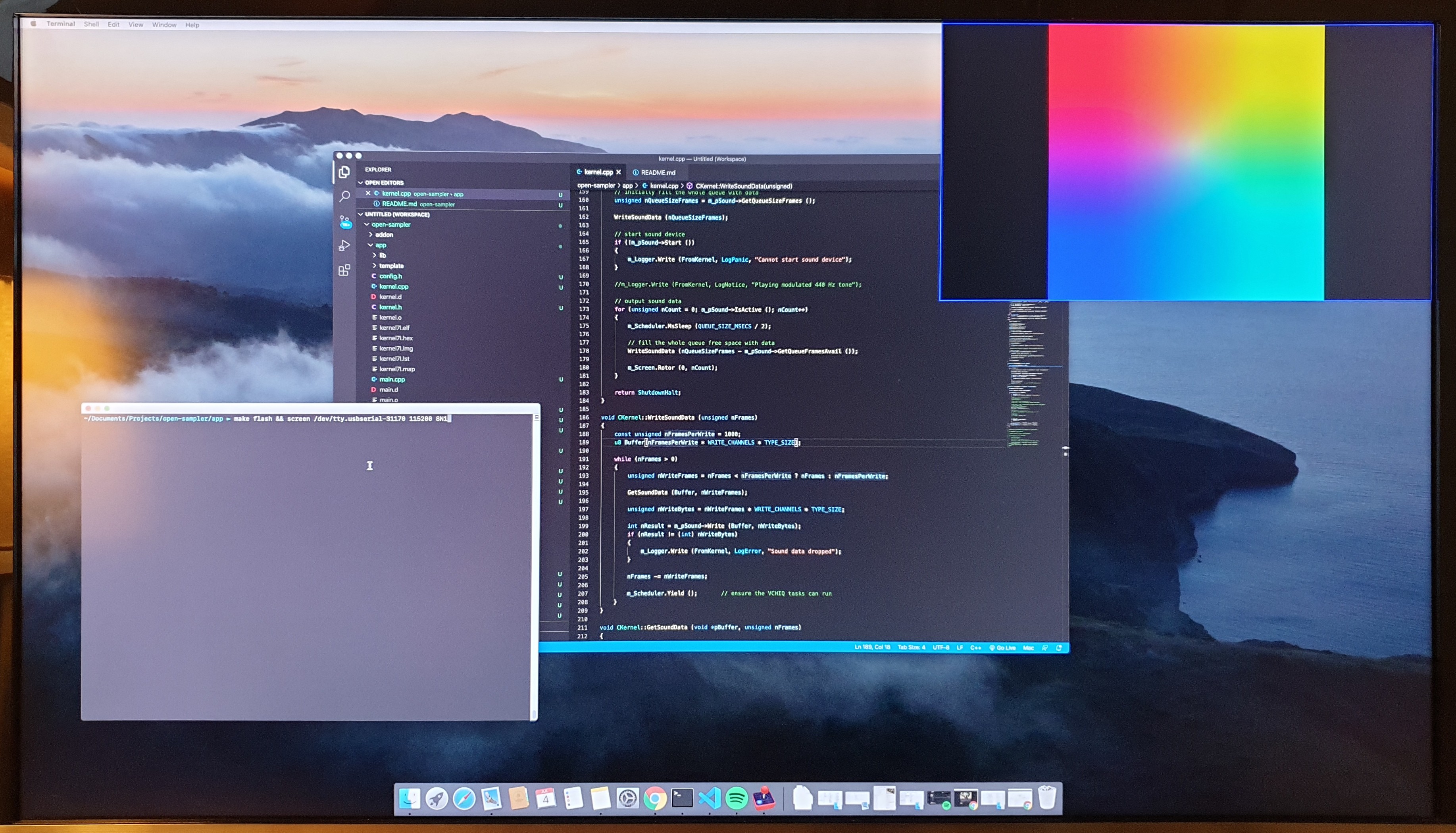
To see the log information from the serial port on your mac, you can use the following command (replace the first parameter with your own usb serial device path):
screen /dev/tty.usbserial-31170 115200 8N1This might not be obvious, so I'm just going to say it; to get out of the screen command use the following key combinations:
Control-A followed by Control-\ and y
If you want an all-in-one command that will start monitoring the serial port after flashing, you can do:
make flash && screen /dev/tty.usbserial-31170 115200 8N1Soldering a reset switch
To reboot the pi, you can buy a USB-C Power adapter with a switch, or you can solder a reset switch to the Pi 4s board. Under the Rapsberry logo, there are 3 holes for jumpers, it's called 'J2'. if you short the right two pins (GLOBAL_EN and the one next to J2), the Pi will reset. I did a quick (and not so very good, but fine for now) solder job and connected a switch that allows me to reset the Pi when I want to.
![]()
That's it!
So that's it for now, our build environment is ready and set up. I found it handy to include a reset switch, and to have the hdmi out port of the Pi hooked up to my 4k computer monitor using picture-in-picture. I have ordered an official Rapsberry Pi 7inch touchscreen, since Circle has also built-in support for the touchscreen part. But until then, we're ready to rock and roll!
openSampler
a hardware sampler based on the raspberry pi running bare metal (so no Linux)