Andrew Mitz
-
Remote receiver
01/20/2025 at 04:00 • 0 commentsI decided to add a remote receiver. This allows the Player to be further from where the controller is used. In my case, the player sits on top of the wall-mounted TV set. The controller is on a table below the TV. Usually, the arrangement works well. But as the battery runs low on the controller, the Player starts missing button presses.
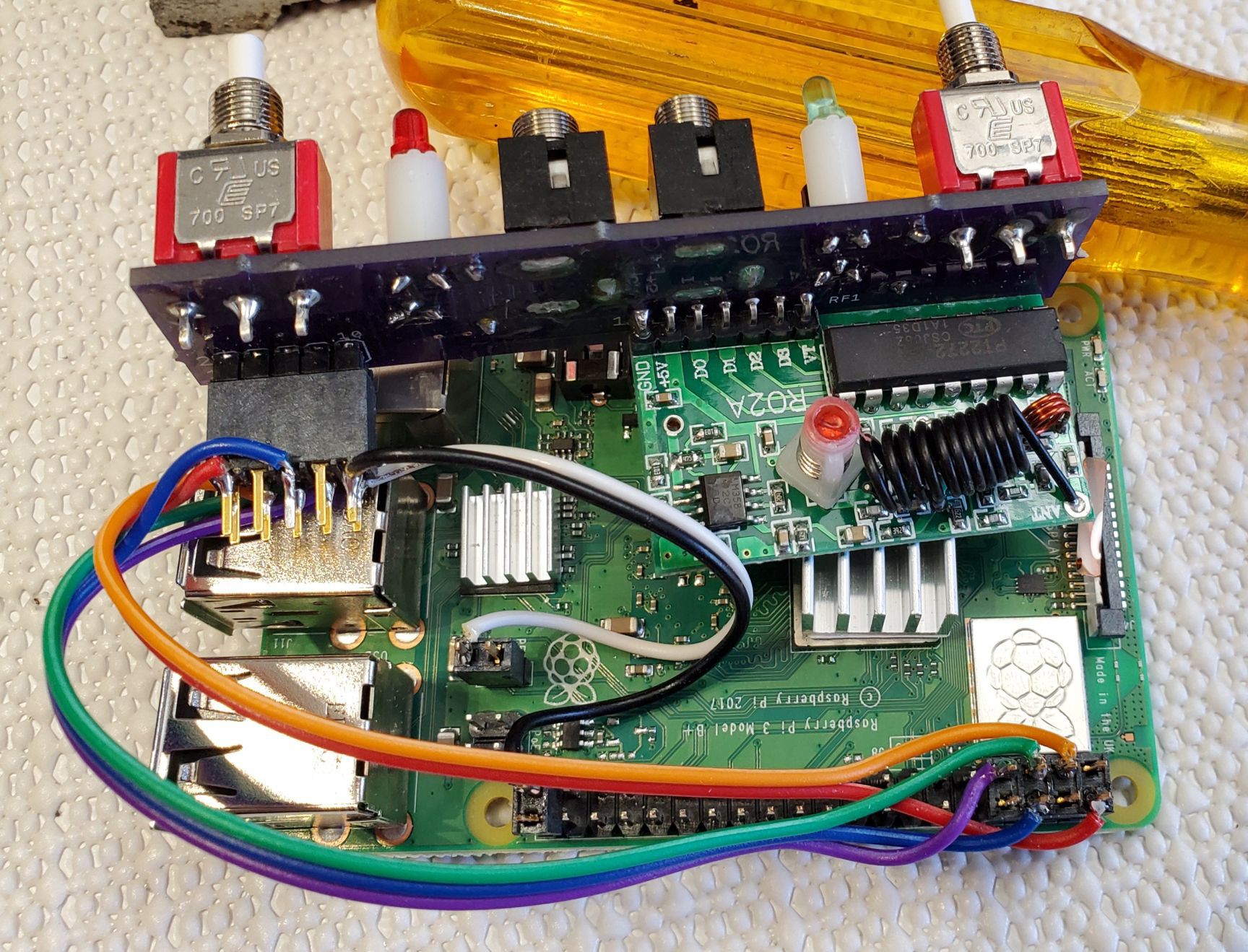
I put the Player circuit board into a small box without the Raspberry Pi. The START and STOP pushbuttons are not used but can be installed to help with mounting the circuit board in a box. Do not install the 10-pin connector. The circuit needs 5 V. My prototype is powered by a 5 V cellphone charger through a USB A cable that is cut to pull out the ground and 5 V power connections. Standard 3.5 mm mono cables are used to connect the remote receiver to the Player. Be sure the left 3.5 mm socket on the remote receiver goes to the left 3.5 mm socket on the Player. Mixing up left and right will confuse the Player. I could not find a source of long 3.5 mm mono cables, so I bought connectors and wire and made my own.
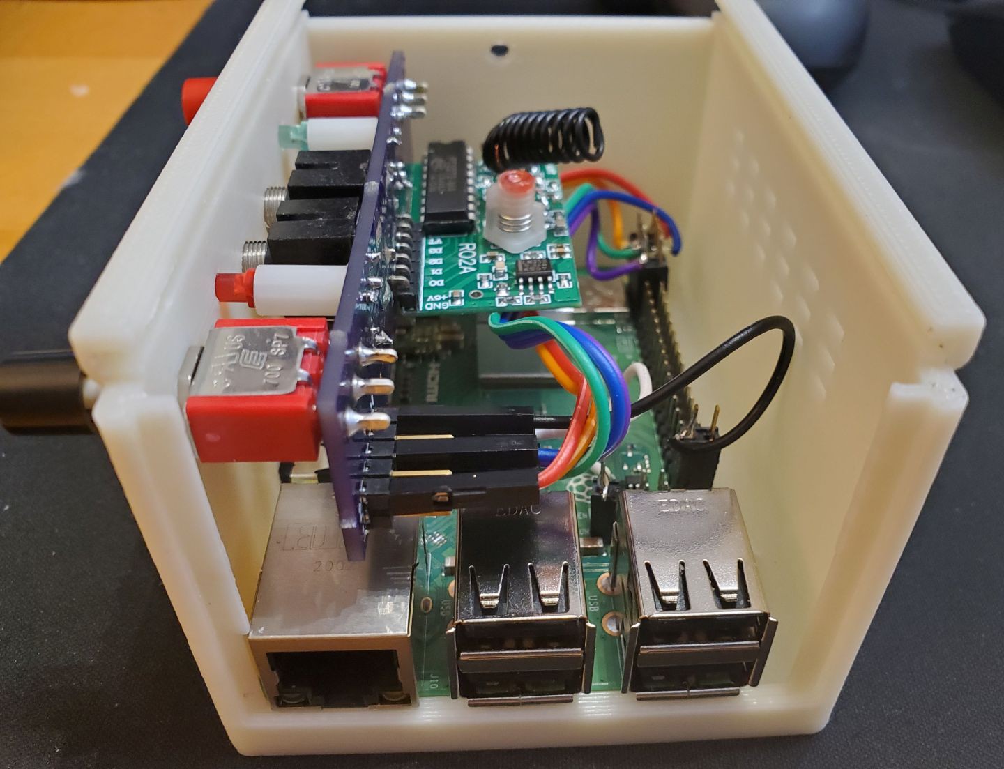
With long enough wires, I mounted the remote receiver on the back of the table where the controller is used. The short distance from the controller to the remote receiver makes the system reliable until the controller battery is discharged.
As always, I do not consider the new design or use-case final until it is proven effective over months of use. As of this writing, the prototype has been installed and is in use.
-
Wiring between the Raspberry Pi and the front panel PC board
11/14/2020 at 21:18 • 0 commentsThe writing between the Raspberry Pi and the front panel PC board is slightly different among the Raspberry Pi 3B, Raspberry Pi 3B+ and Raspberry Pi 4. I use a Raspberry Pi 3B+. The 3B and 3B+ run cool, which provides many hours of service. The Pi 4 is much warmer. I would rather not run it without a small fan. Fans tend to fail over time, so the 3B or 3B+ seems like a better choice. I buy the 3B+ because it is a newer design, but the 3B works file.
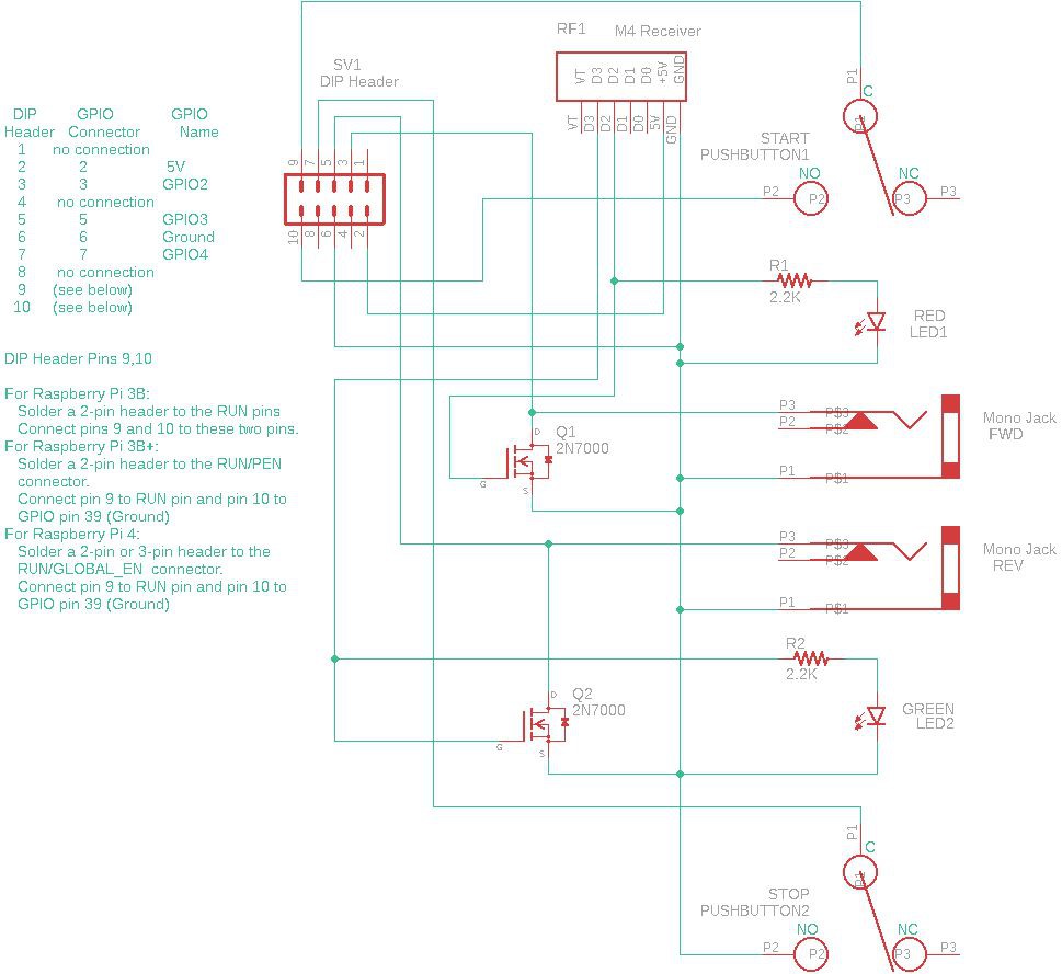
To make the wiring differences more clear, I have updated the schematic with notes on each Raspberry Pi. I
![]()
To make a simple harness I like to use a 10-pin female header to plug into the front panel board. I use an 8-pin female header on the GPIO header of the Raspberry Pi. I solder color-coded ribbon wires between the two using standard color codes. The pin mapping from the front panel board to the GPIO pins are 1:1 for these pin numbers: 2, 3, 5, 6, 7. The last two pins of the 10-pin header connect depending on the specific Raspberry Pi board.
For the Pi 3B, simply wire pins 9 and 10 to the two RUN pins. Note, on all the Raspberry Pis, you must install a male header on the RUN pins yourself. I find this a big annoyance.For the Pi 3B+ or the Pi 4, connect pin 9 to the RUN pin. Connect pin 10 to GPIO 39, which is a ground. The RUN header is 2 pin on the Pi 3B+. On the Pi 4, the header has three contacts and is called RUN/GLOBAL_EN. It still has a RUN pin.
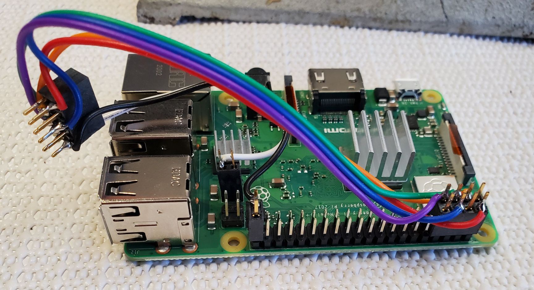
This picture shows the wiring of the cable harness before assembly. The example is a Pi 3B+.![]()
The next picture shows the harness wiring attached to the front panel PC board.
![]()
-
Autodesk and STL files added for 3D print case
11/01/2020 at 20:00 • 0 commentsAn Autodesk Fusion 360 export file and three STL files have been uploaded. This is a custom case for the PlayVideo. It has a general purpose Raspberry Pi 3B mounting on the bottom and the top section has holes for the PlayVideo printed circuit board. Note, the Autodesk file is suitable for anyone who wants to build a Raspberry Pi project with space above the board for a circuit and connectors. The layout fits the Raspberry Pi 3B and 3B+.
![]()
Note one side is removeable. When in place, it holds down the circuit board. The top holds the side panel in place. The top is secured with a single #6 screw.
-
Be careful about mounting the pushbutton switches
10/05/2020 at 21:18 • 0 commentsBe careful when assembling the PlayVideo Interface printed circuit board. All parts except the RF board and the 10-pin header mount on the front of the board. The front has most of the part markings. The RF board and header mount from the rear. Perhaps more subtle is the mounting of the two pushbutton switches. The board has the markings: C NO NC for each switch. The switch fits into the board two ways, but only one orientation will put the COMMON on the left and NORMALLY CLOSED on the right. If you get this backwards, the circuit will think the switch it is being pushed continuously.
-
New case (soon) and issues with RUN pin on Pi 3b+ and 4
10/05/2020 at 21:09 • 0 commentsMy next step is to create a custom case for the Pi 3b and front panel board. If all goes well, I will have a 3D printed case to hold both (rather than two separate boxes).
One issue that has come up switching from the Raspberry Pi 3b to the 3b+ is the "RUN" header. On the Pi 3b, the second pin next to the RUN header is ground. The "Start" pushbutton of my interface uses these two pins. On the Pi 3b+ the second pin next to the RUN pin IS NOT GROUND. It is the PEN pin and cannot be used with the Start pushbutton. Also, none of the pins on the POE connector have a ground pin. For the Raspberry Pi 3b+, connect the Start pushbutton between the RUN pin and one of the ground pins on the GPIO header. The most convenient pin is probably pin 39. The Raspberry Pi 4 has a slightly different pin configuration, but the instructions are the same. Connect the Start pushbutton between the RUN pin and a GPIO ground pin.
-
Version 1.1 of pc board. Drill template.
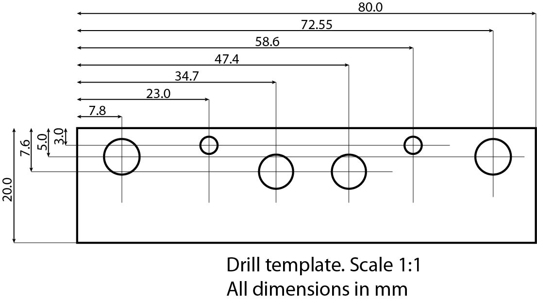
08/06/2020 at 22:39 • 0 commentsThe m-pad-2.1 Eagle library has the 2N7000 TO-95 transistor layout wrong. I had to fix that. One pushbutton switch was inserted backwards. I added silk screen markings to make the orientation clear. I ordered an updated set of PC boards from OSH Park. Meanwhile, I created a drill template in Adobe Illustrator. Here is a jpg of the file.
![]()
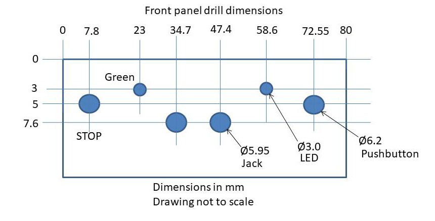
The following drawing shows the hole sizes. Note, this is not to scale.
![]()
-
Printed circuit board for the interface
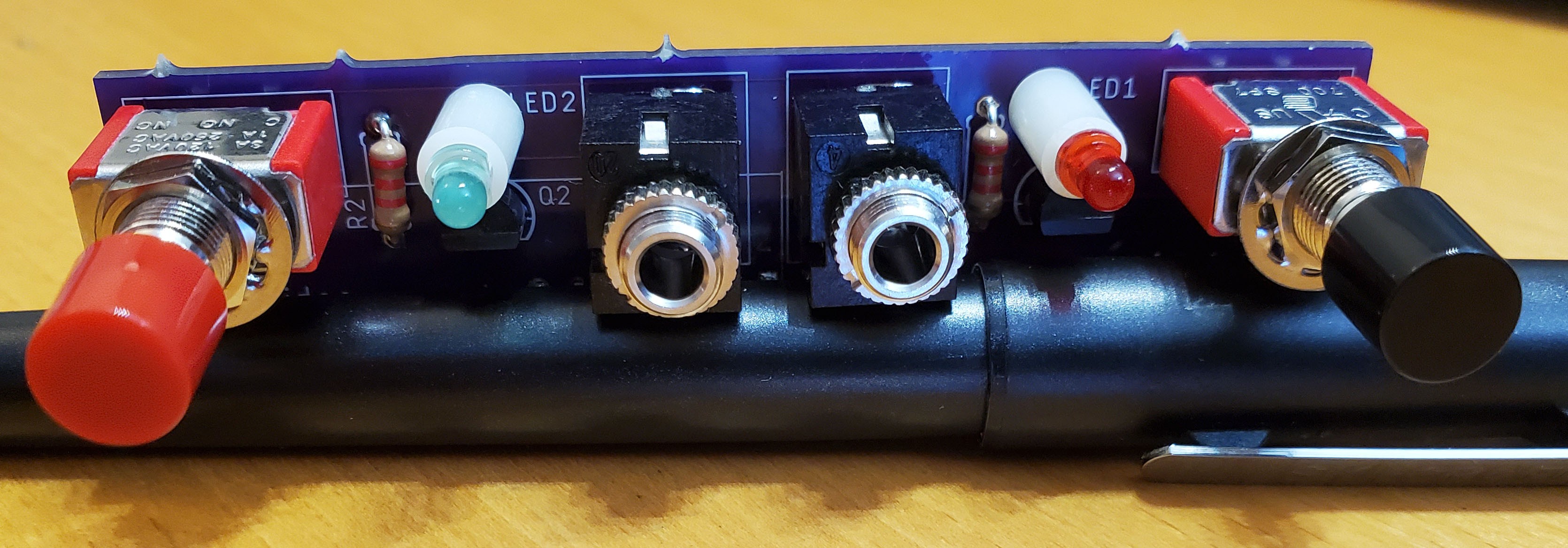
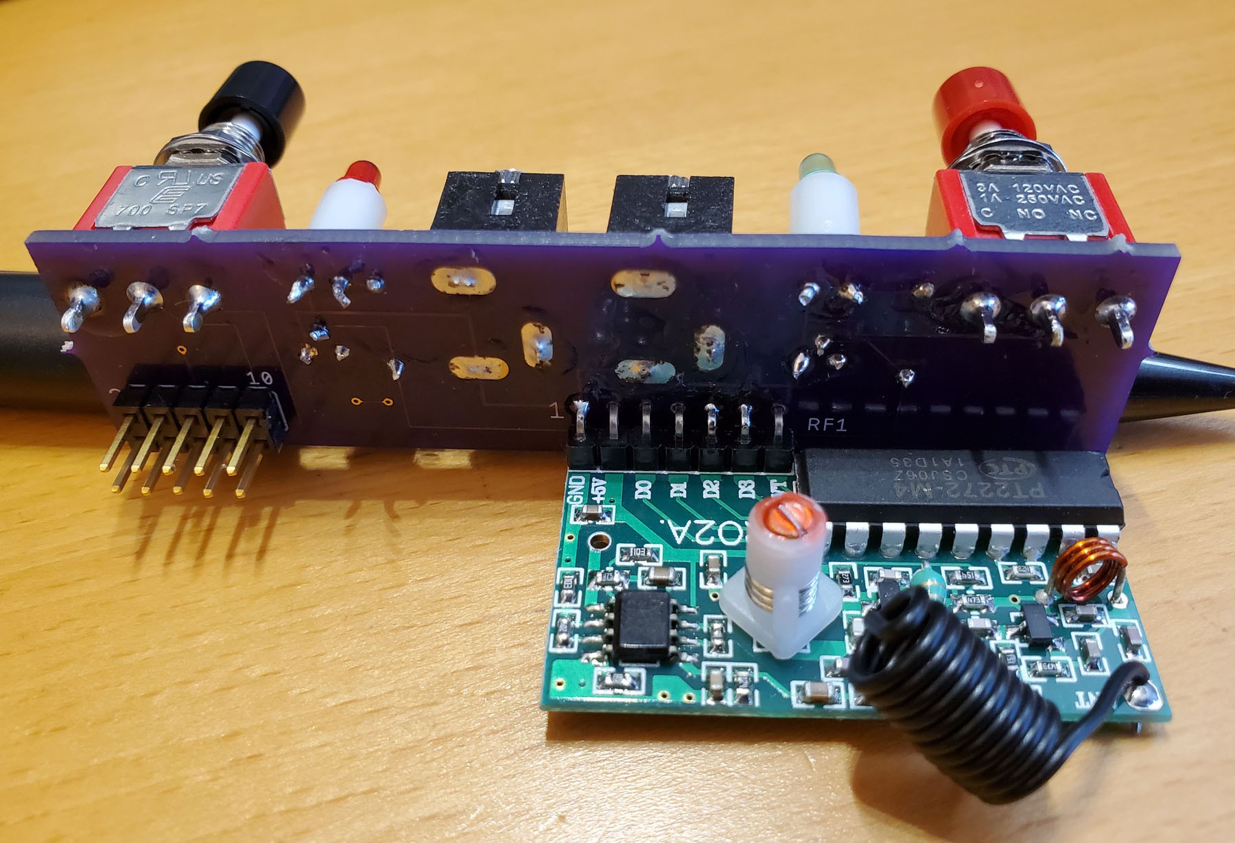
08/05/2020 at 21:17 • 0 commentsI decided to design a circuit board for the interface box. Version V1.0 is built, but not tested yet. I expect it to work. V1.1 is already designed. It fixes a few holes and some component spacing. Here are some photos.
![]()
![]()
PlayVideo: adaptive video player
Use a single adaptive switch to play any video in the library