 kmatch98
-
1CAM it up
A major issue with getting this to work was designing the cams. I found some guidance that the cam “pressure” angle is critical. Here is some guidance on the maximum pressure angle depending on the follower design. Actually when I found this info, I changed my design from a translating cam follower to a swinging cam follower. I found that the translating follower is more likely to jam than a rotating follower and that jives with this guidance. I couldn’t figure out exactly how to calculate the cam angle automatically in Fusion 360 but I made a sketch that I could drag a line around and estimate it.
Maybe y’all can show me how to display the maximum pressure angle on my cams in Fusion 360.
-
2Print in Place can be your friend
I’ve been reading tutorials about designing for print-in-place for 3D printing. I realized that it can reduce a lot of the assembly effort and reduce the parts count. Assembly is sometimes enjoyable (like LEGO) but I wanted to make this thing less fidgety if I could. My first target was to make as much as possible as print in place. I first made a test with a single display element with the front, the display piece and the two links and the two pins all as one piece. Yay I thought. But I had to ad some support for the links and somehow I never could get them designed so they had smooth operation and decent tolerance. Either they had too much friction and wouldn’t rotate smoothly or they were flopping around with too much wiggle room. So I decided to change the links to a separate print (but the two links print connected with printed in place) and then I had to add these pins in.
This added back three more pieces per display element, which went against my goal, but in the end I was much happier with how it operates. Such is life I guess. I guess my goal should have been, make it work while not giving myself too many hassles.
Maybe our future selves will figure out a way to print more of it in one piece with tight tolerance and smooth link motion. Let me know, I’ll be the first to check it out. -
3More details about making this thing.
Here is a list of parts you will need, along with quantities:
- 4 segment
- 3 segment
- Links (7 quantity)
- Pin, large (7 quantity)
- Pin small (7 quantity)
- Cam A
- Cam B
- Cam C
- Cam D
- Cam E
- Cam F
- Cam G
- Back Frame
- 33T transfer gear
- 13T drive gear
- Handle
- Bright colored paper to stick to the display flappers
- Optional: m3 nuts and bolts (8) and some glue to fix the nuts to the display sections
Total of pieces:
3D printed components (16 different components, total of 13+21=34 pieces)
optional nuts & bolts
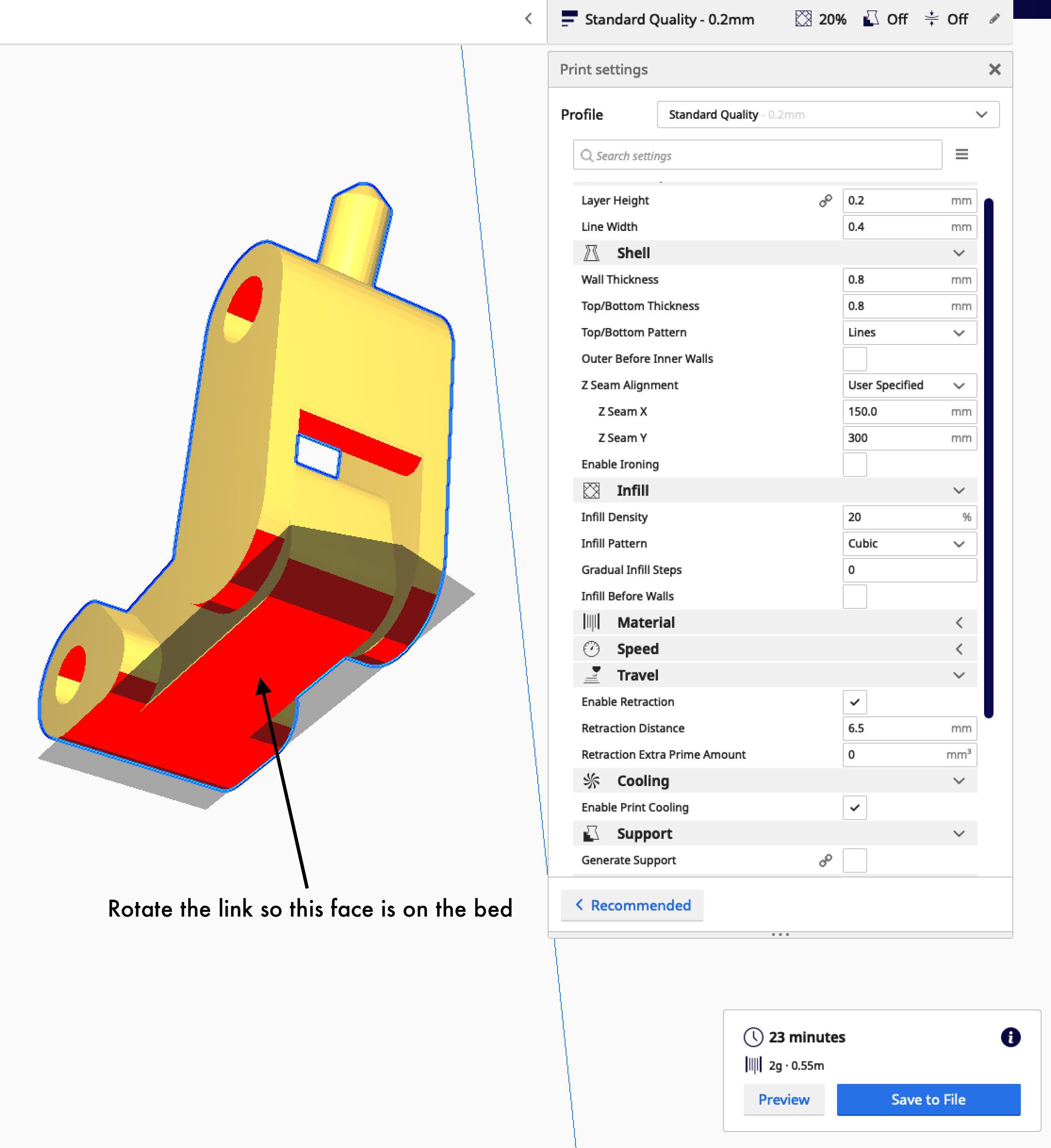
Here's how I print the link, with the bottom on the build plate.
![]()
-
4Frame Attach to the 4-segment and 3-segment displays
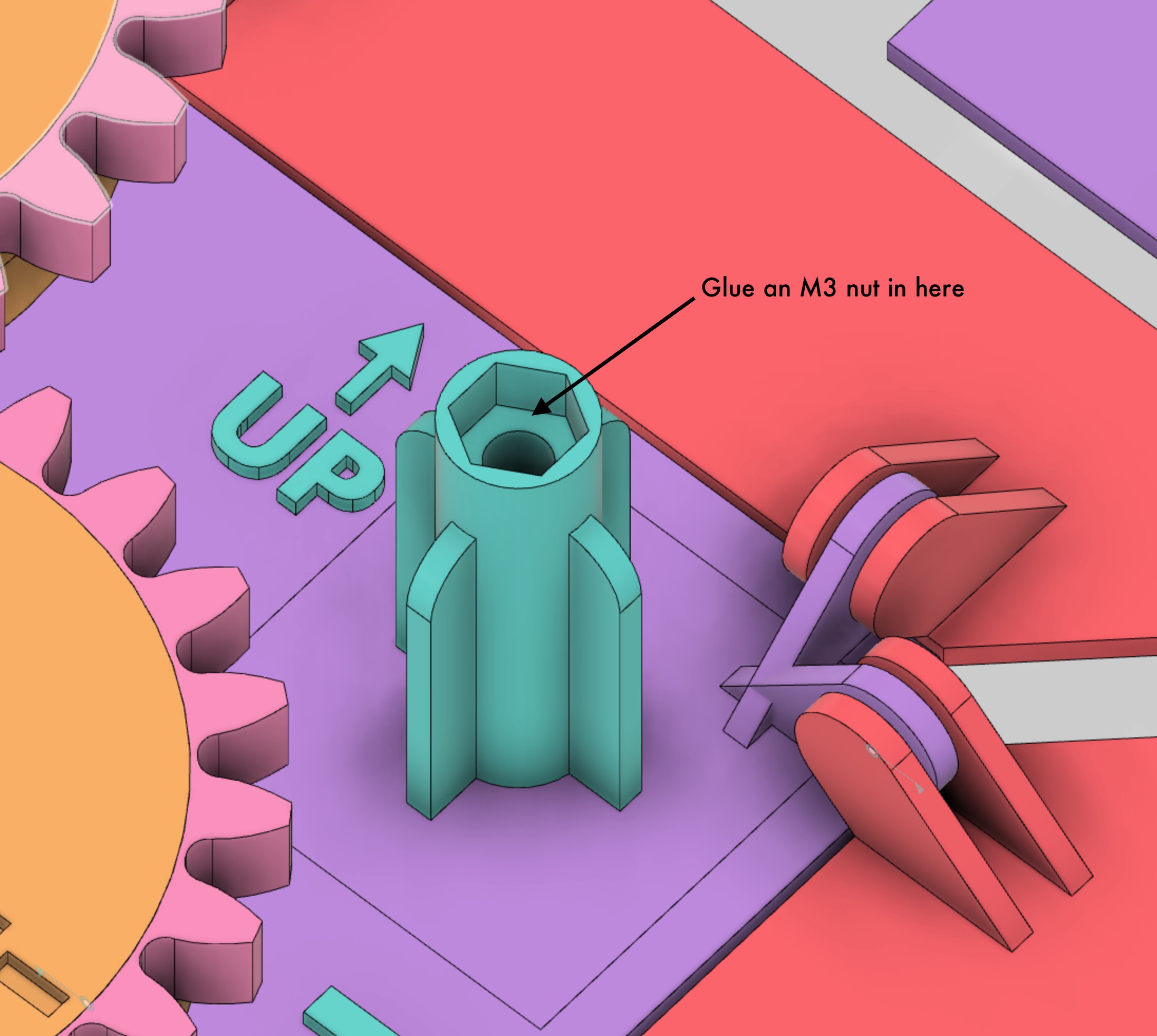
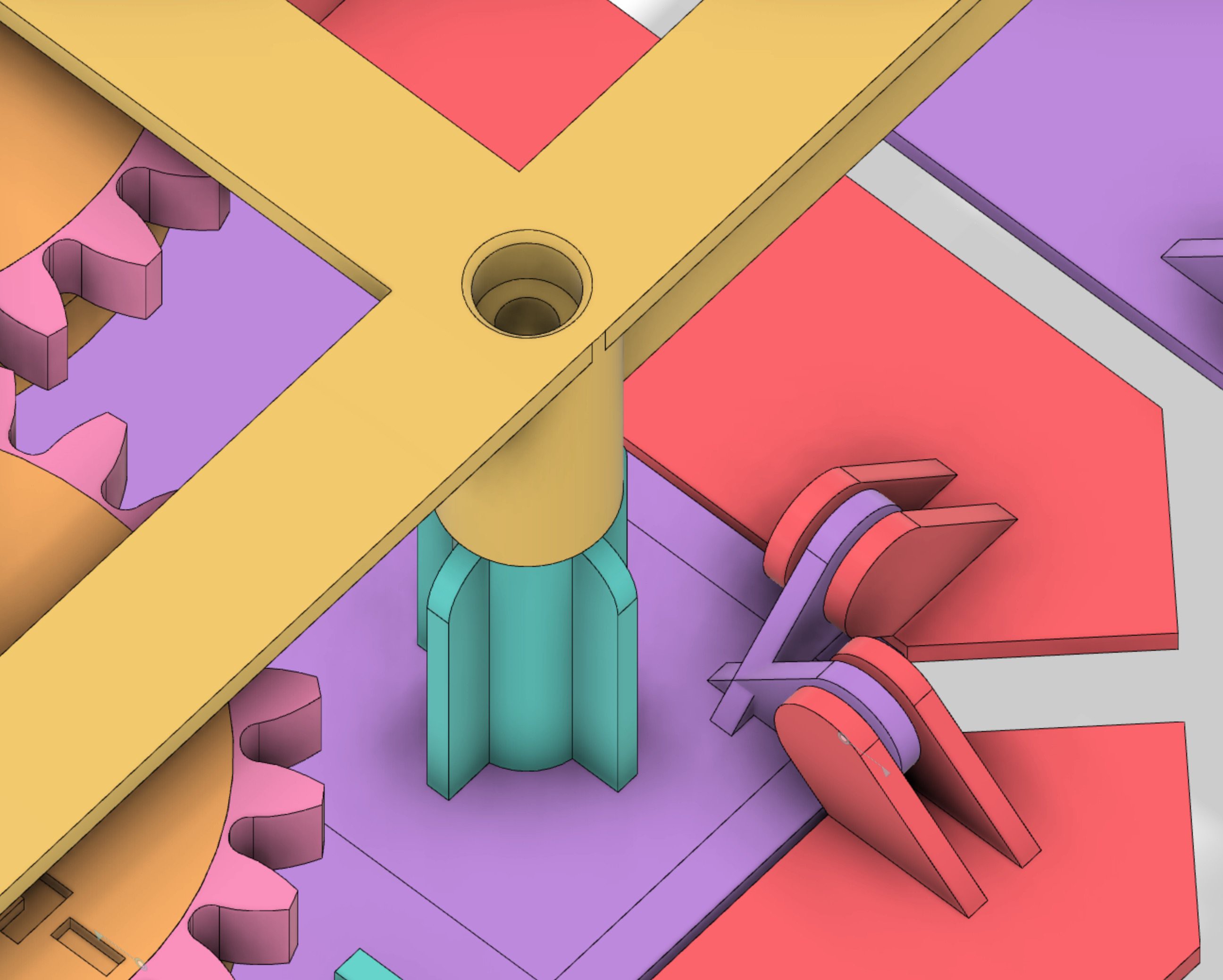
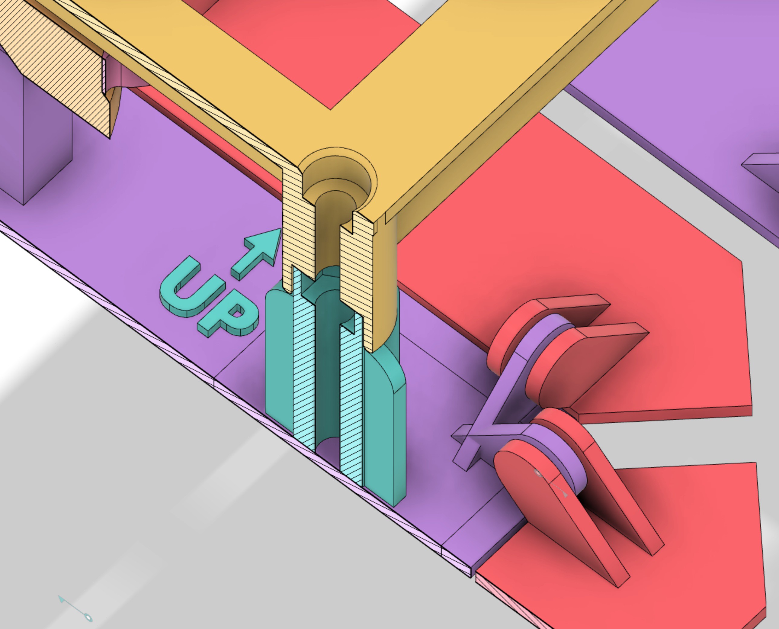
Here's how the Frame attaches, you can use some M3 nuts/bolts if you want it to be secure.
![]()
![]()
![]()
-
5The missing Link
I got a note from adcurtin saying that the link was hard to print. I had some trouble printing it myself a few times and then it started working for some unknown reason. So, clearly it is a finicky design due to the small contact area.
I made another Link design (see file: Link_easier_to_print) and let's see if adcurtin has any luck with it.
New link design:
![]()
-
6Smaller Display test piece - I hope to save you some time, filament and heartburn.
Before committing to a large print of the "3 Segment" and "4 Segment" pieces, you probably want to verify your settings on something smaller. Also you will get a feel for how the mechanics of this bugger works. This test piece one is 75 mm long (while the full sized ones are 132 mm long).
So, I added a file called "Display test piece-smaller.stl" that takes me about an hour to print (0.2mm layer height). It's the same dimensions as the big one, just not as long in the long-direction. But the links and cams should operate about the same.
Even with out a frame, put a cam and link on this one and hold it up and orient it in different directions while you turn your cam, like it is hanging on the wall. Use some gummy funk to temporarily keep the pins in place so they don't fall on the floor. Then you can see how yours floppy-flaps in the different orientations. You may need to sand the tip of the link to get it slippery-sliding in the cams. I had to.
One more trick you might not see: I added a little cutout in the pivoting shafts to account for some droop during printing of these shaft overhangs.
-
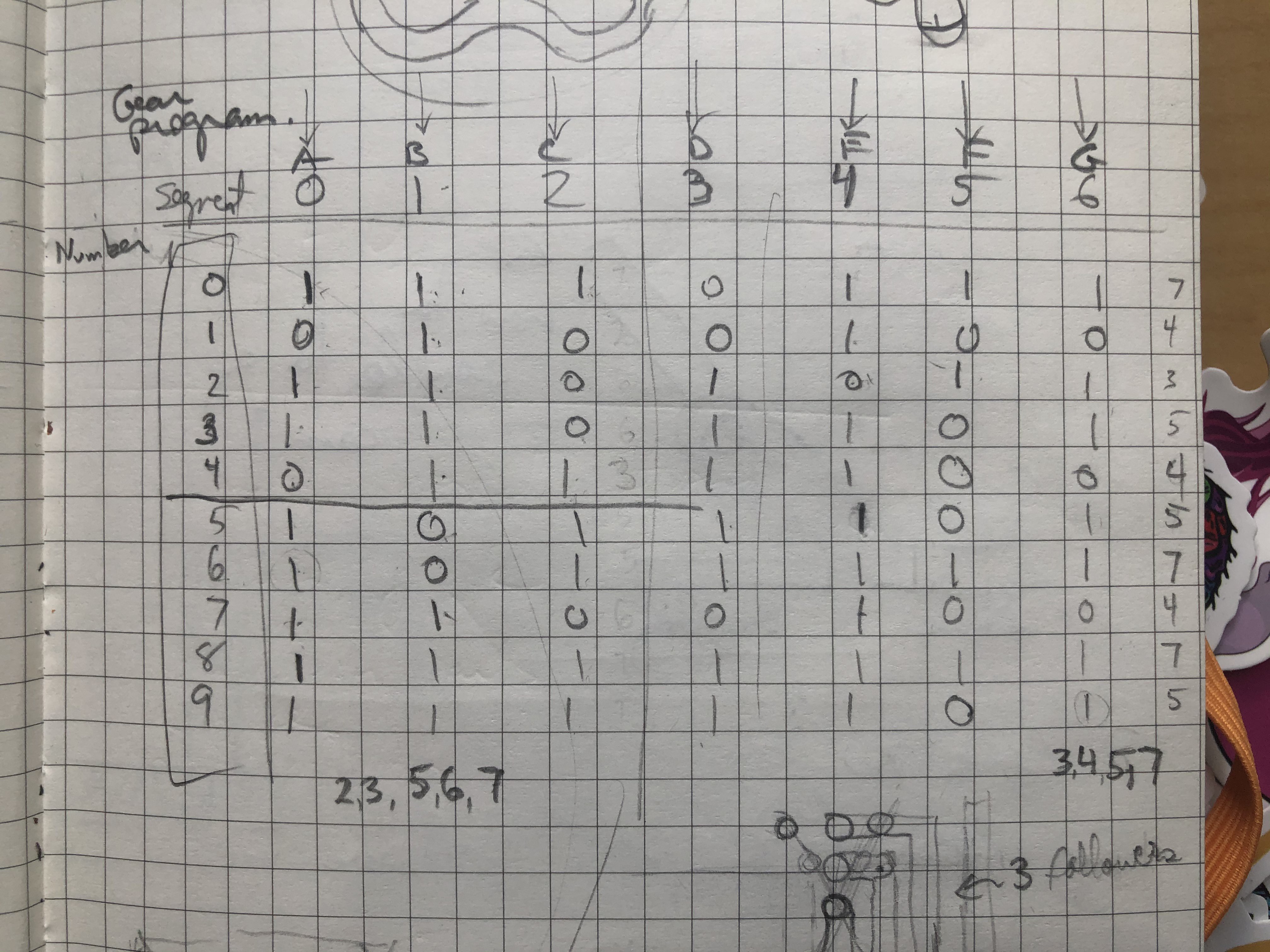
7Yes you CAM!
Cam wheel Programming is tricky for me so I wrote some diagrams below to help me sort through. The first was a logic table for each display bar:
![]()
next I made this map of the rotation direction of the cams (viewed from the back of the unit):![]()
And then this polar type diagram that I used to do the work in Fusion 360. The lines connecting the dots indicate the link pin movement in the cam slots:
![]()
the outer numbers are the number that should be displayed. You can see that the A and B cams rotate in opposite directions from this chart.
I went over the binary table a few times to convince myself it was accurate. Then each time I would design a cam wheel, I thought about it several times with these charts before I opened Fusion.In the Fusion file each wheel has a separate component and then the main file brings them all together. I could probably use some tips on organizing a big project. This is the most complex thing I’ve designed so far so I could probably make it easier on myself by being better organized.
Mechanical 7-Segment Display
Clickety-clackety goodness to display a decimal number


Discussions
Become a Hackaday.io Member
Create an account to leave a comment. Already have an account? Log In.
merci, cantanna
Are you sure? yes | no
super ce projet, tres beau travail...
Are you sure? yes | no