Close
0%
0%

vector-06c mini

A 50% size replica of my favourite 8-bit computer

Public Chat
Similar projects worth following
C64 mini is very popular and I'm envious. Because nobody is going to make a cute little Vector-06c, I'm going to build one myself. Today the original ones in good condition are very rare. Wikipedia has a summary of what it is: https://en.wikipedia.org/wiki/Vector-06C

2023

Current target platform is 5.0" ESP32-8048S050. It's an upscale variant of "cheap yellow display" with a 800x480 IPS screen. Driven by ESP32-S3 LCD peripheral, it allows custom refresh rates. It suits perfectly my 50Hz emulation needs.

2024

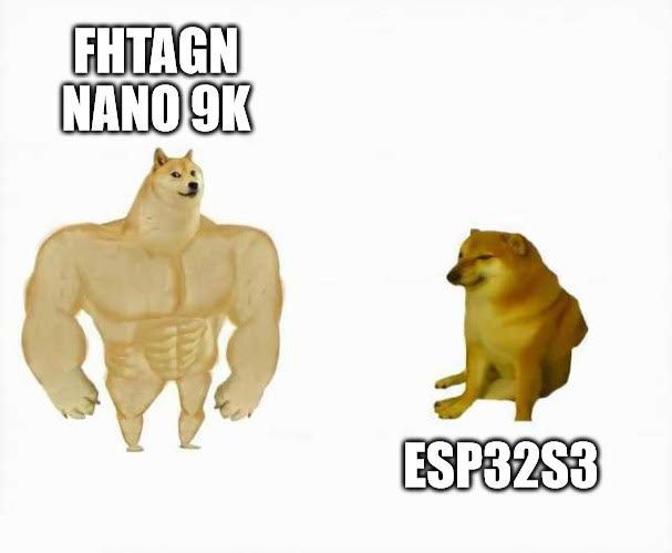
New target platform: Tang Nano 9K.

  • 1 × ESP32-8048S050 5.0" Yellow Board based on ESP32-S3
  • 1 × Sipeed Tang Nano 9K + 5" 800x480 display FPGA board

  • New case and audio crackling

    svofski07/26/2026 at 09:55 0 comments

    The firmware has become much more stable after I figured out the problems with SPI bus.

    Unfortunately there remains a bunch of problems that I still cannot figure out. Most prominent is audio crackling. I swear I tried everything and the main loop and the audio system seem to be reasonably optimised, but the crackling persists. It could be a memory congestion problem, but could be something obvious that I just fail to see at this moment.

    It's worth noting that increasing audio volume resets the controller despite of huge capacitors I have added. But it's a separate issue.

    There are also obvious palette programming/timing issues that probably stem from overzealous optimization. They were there before this last cycle, they have changed but didn't go away unfortunately. Some raster effects work, others don't.

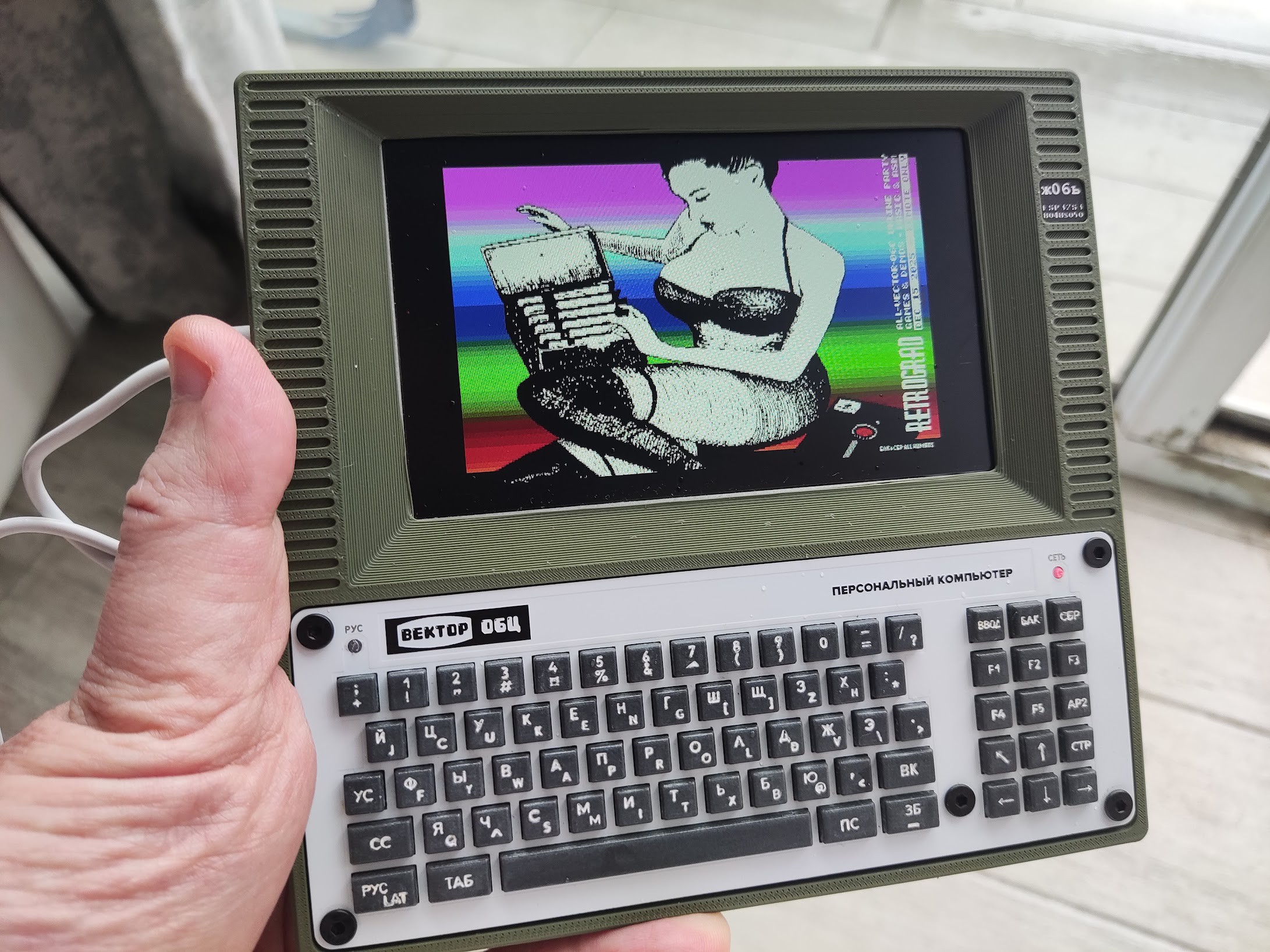
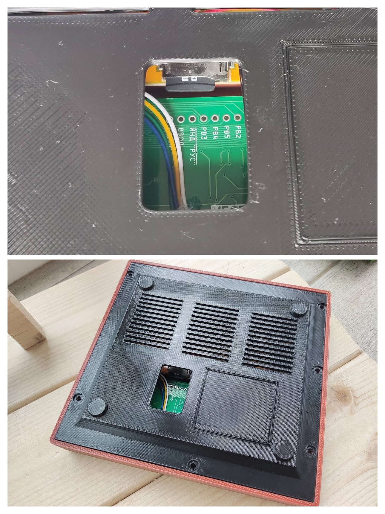
    For now it's time to celebrate that the stability has greatly improved and reflect that in making a new sturdy and stable case for it. Not my first choice of colour but it will do:

    SD card access really is hard and the only real solution here is an extender which I currently don't have. Something to improve on later:

    Until the next time!

  • Revisiting the esp32s3 version (SPI keyboard)

    svofski07/03/2026 at 11:18 0 comments

    After quite a long break I decided to take a look at the old v06x-tiny project with the tiny keyboard. I put it aside out of frustration 2-3 years ago. Who knows what you can see with a fresh look.

    On the power-on not much has changed. Keyboard seems to work, SD card seems to kinda work maybe 1 out of 4 times, then fails quickly anyway. 

    Recompiled both the esp32s3 host and rp2040 keyboard. Both needed a bit of a makeover due to SDK updates.

    All good, but now it doesn't work pretty much 100% of the time. I still don't know if it's a random fluke or something in the updated SDKs.

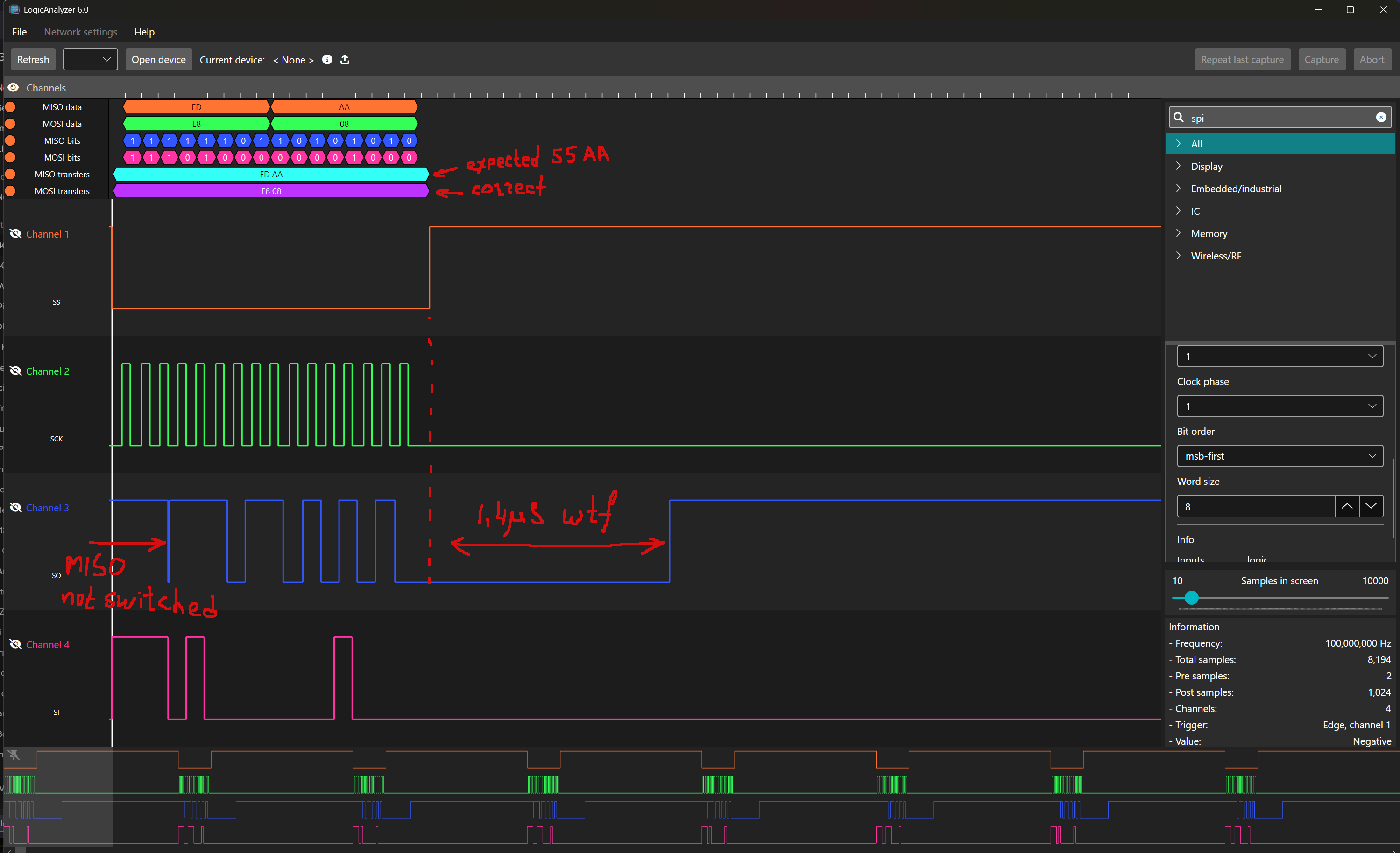
    I frequently hear about people using logic analysers but I never had a use for one. Isn't it the perfect time for one now! There are two different rp2040-based logic analysers. One is called sigrok-pico, another is called "LogicAnalyzer" by gusmanb. With both I had trouble making them work on Linux aarch64, both worked fine on Windows. I expected this to be exactly the opposite, but it's ok. After some trial and error I settled with LogicAnalyzer because it seemed a bit more direct. Because I have one board with all 3V3 logic, level shifters should not be necessary.

    Probing the bus helped me remember why I wrote some angry things in the code, and even angrier things in code comments back then:

    What we're seeing here is probably the reason why we don't see many implementations of SPI Slave devices based on RP2040. The hardware peripheral can't handle MISO swichover on SS, and programmatic switchover takes time. This makes me lose first 4 bits in front of every response and adds a fairly long delay in MISO switchover to high-Z after SS goes high. This delay probably causes more conflicts with SD peripheral when it's active.

    Update

    SPI switchover solution: PIO SPI SLAVE

    Builtin peripheral cannot switch MISO pin direction automatically, this has to be done programmatically and there's a great delay attached to that. It can be done with PIO though.

    I'm not sure why implementing PIO based SPI slave was so hard, it seems like a trivial thing now. Several mistakes that set me back a day or three:

    • I sampled SS level instead of edge. Fix: sample SS edge.
    • wait on clock transition without bit counting, expecting the transaction to end by SS going high, but SS-going-high detection code would not execute because the code was stuck in wait clock. Fix: count bits and end transaction when 16 bits shifted out.
    • autopull, but sometimes the fifo would be drained mid-transaction ~ still unsure how it works. Fix: explicit blocking pull at the beginning of transaction

    It seems that implementing a properly robust SPI slave is still a hard task even for the mighty PIO. Maybe this is why you don't see many PIO based SPI slaves out in the open. Now I have one. 

    SPI electrical issues

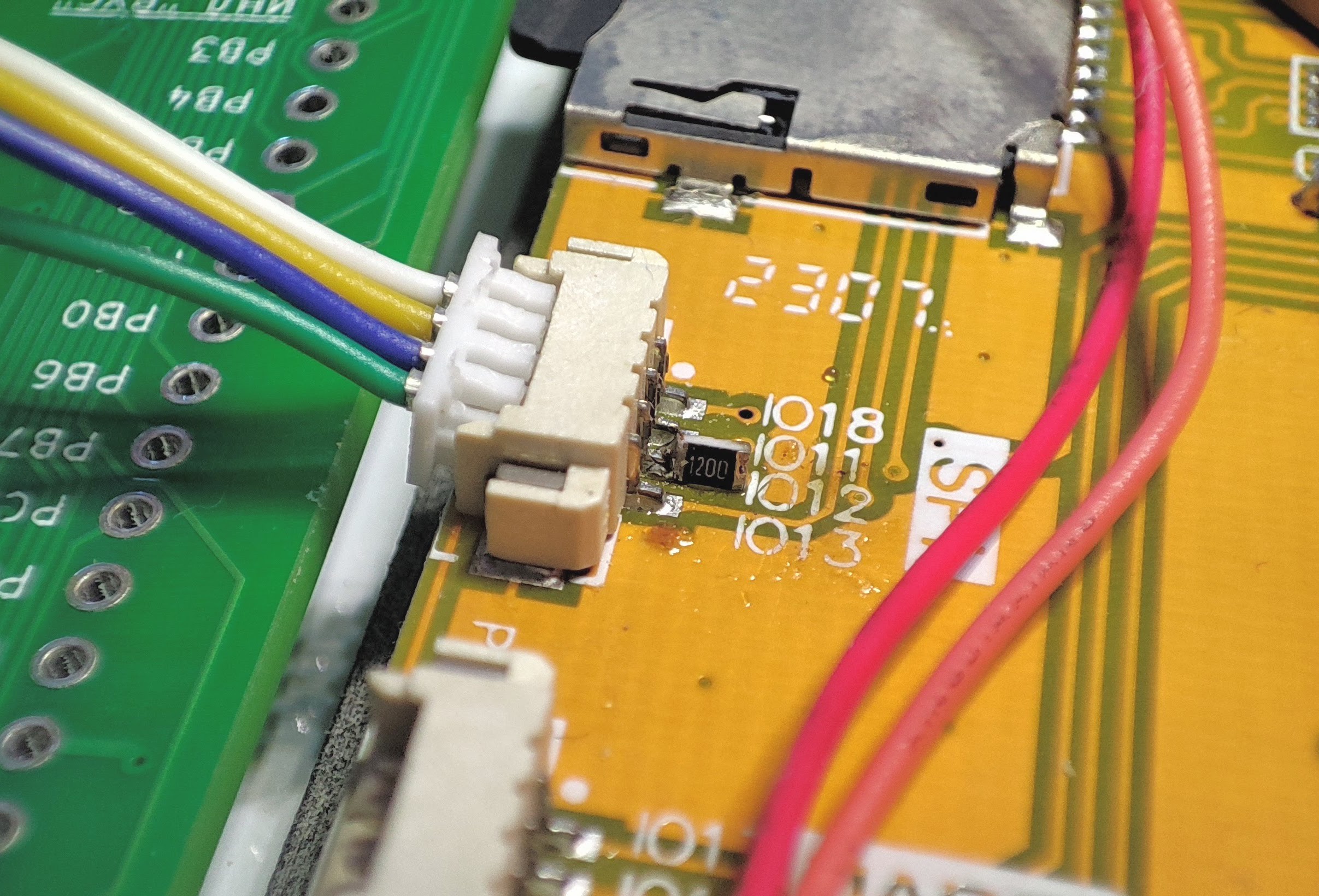
    However after seeing nice and clean keyboard transactions in the analyzer I still had SPI errors. After some testing and shifting blame between various things I singled out the CLK wire going to the keyboard. Apparenly it's too long and twisty and simply connecting it distorted communication with SD card. 

    The fix: 120 ohm series resistor at the connector. Minimal surgery:

    And hoorj! The keyboard + sdcard work together. 

    Core takeaway: taking a 2 year break is sometimes the most productive thing you can do.

  • CAS format support

    svofski09/11/2024 at 08:30 0 comments

    CAS files are a sort of container format for storing data as it was saved on cassette tapes. It was used primarily by BASIC, and there are several variants. The native BASIC used two formats for CSAVE (tokenized Basic program) and BSAVE (raw data image), the modulation used was PSK, same as ROM loader. BASIC-Korvet used a more sophisticated MSX CAS file structure, although probably only a subset of it. These files are FSK-modulated, which is not typical for Vector-06c.

    I had 12K allocated for instruction ROM in my NEO430-based subsystem. And even with the incredibly compact msp430 code, the new features grew up in size and I have reached the 12K limit. It turned out however, that due to BRAM memory structure, allocating 16K (which is 8K 16-bit words) takes the same amount of BRAM blocks, so I was able to expand available ROM for even more features.

    Supporting CAS files means generating a sound based on CAS file content on the fly. Loading happens as if it was a sound recording.

    So far I have implemented loading BASIC 2.5 CAS files. BASIC-Korvet is a bit more involved, but it will be added soon.

    Here's a little video update which I hope you'll find enjoyable.

  • Tang Nano 9K Rant

    svofski09/04/2024 at 16:03 0 comments

    I have added a couple of features that I should have added a decade ago, namely ROM file load and WAV file load. They are far from perfect, but it's a start. For example, ROM load requires that it's reset into tape loading state first (F1+F12), and there's no good visual indication of operation progress. For some reason I've yet to discover, not all WAV files load well. For example, I can't load a turbo load wavs, nor can I load a program saved from Basic-Korvet. I will demo all that in due time. Meanwhile I've been stuck on something completely ridiculous...

    I've been playing with sound, and even though I had nice improvement in my PWM output, it's still pretty noisy. So I wanted to measure the noise when powered by PC vs powered by a power bank. For this to work I needed to program the flash so that it cold boots. I did that many times already.

    So I flash it, but suddenly I get an error and a Status Code: 0x00035421. Awesome.

    GowinSemi tech support promptly responded. Turns out that if I updated the programmer, I could also click on Status Code line in the log and see it decoded. It decoded to CRC ERROR. So I updated the programmer, tried it again. This time it decoded to BAD CMD.

    I immediately guessed that the flash must be dead. But I decided to try to flash another project, and tried it with an LCD example. It worked just fine (not without some cable juggling and every version of the Programmer has its own ritual, but eventually it did).

    So I thought maybe my project is too big and it tries to write over some bad sector in the flash. I disabled Floppy support. Flashed the project, it works.

    Oh well I think. Let's enable floppy support back and try it again. Flashed the project, it works.

    ¯\_(ツ)_/¯

    Meanwhile the support responds something about flash needing 1MHz max, and that's the problem with this cable. The cable has a frequency setting in the programmer. But they say it's some different setting. But they give no clues about what I should do to make it work. Oh well... Moving on I guess.

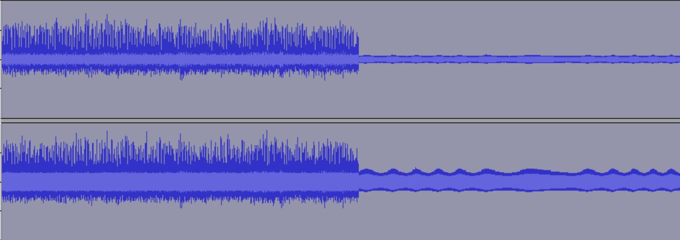
    P.S. Noise (after normalisation) left: PC, right: power bank.


    PWM filtering could be better, but I guess it's okay because all of this happens above audible frequencies.


    Meanwhile, the support responds:

    We do not recommend programming the eFlash of 9K in Tang Nano board due to the USB-Jtag chip.

    If you want program the eFlash, we recommend either make your own board and choose GWU2X or FTDI chip or remove the USB-JTAG chip and put a 4 pin Jtag connector and using our download cable to program in the Tang Nano Board. 

    I guess this is the correct answer, even if this isn't the answer I want to hear. I will continue using the tools at hand and hope for the best.


  • Clean PWM output

    svofski08/16/2024 at 22:10 0 comments

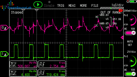
    In my previous update I already had a PWM sound output which was okay for testing, but it was noisy. Regardless of the state of the output, there would be a constant whine and grumble. Not too loud, but it was at the levels impossible to ignore. I connect vector06cc to the same pair of speakers which I have for my main PC and it made it very annoying.
    Of course I tried filtering the power, tried bypassing the virtual ground and all that stuff.. But nothing really helped. The noise was filtering right through the signal lines. I searched the net for a solution. Maybe the search terms weren't right, but somehow it seemed that there's no solution for this. You could find a flat out dismissal ("PWM is digital, your argument is invalid") or a non-solution ("you can't make PWM clean, use a DAC"). I didn't want to put up with that, at least not so easily.

    PWM works by slicing the voltage on the power rail. And if the power rail is dirty, the PWM carries all this dirt farther down the pipeline. So the dirt kind of travels on top of the square wave. And because the dirt can have audible frequencies, you can't really filter it. The solution is actually fairly simple: make a clean power source and use it to re-cut the dirty PWM signal into a clean PWM signal.

    1. make clean power source
    2. replicate PWM using clean power
    3. filter, amplify, profit

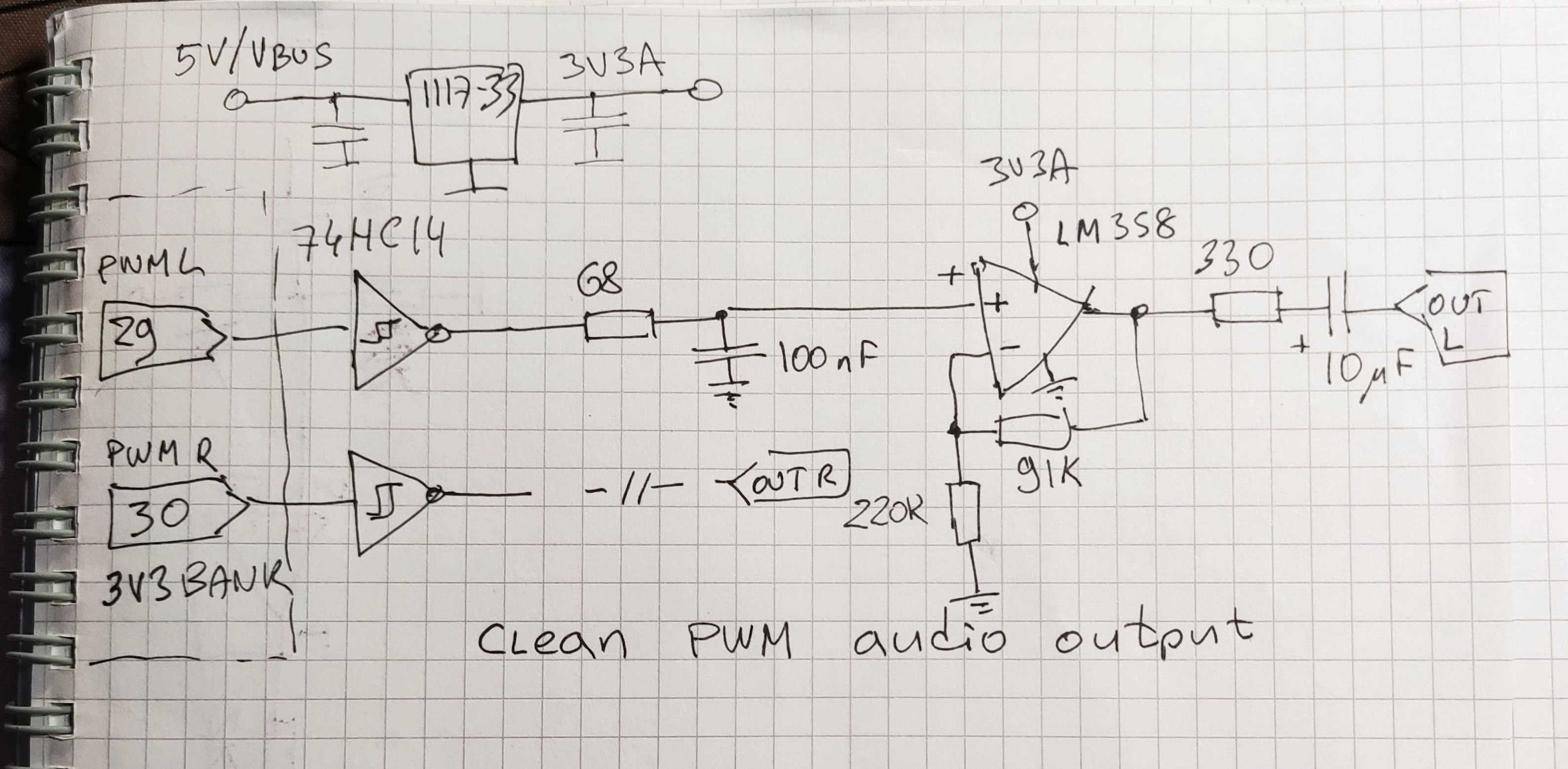
    Here's the schematic that implements this idea. It's very simple, but it's a fruit of a lot of frustrating experiments.

    The crucial part here is the humble 1117-3.3 LDO. I used a drop-in 78xx replacement module which already has ceramic capacitors on it. The output of this module is seriously cleaner than you get on any of the power rails near FPGA. It powers a 74HC14 (which I picked simply because it was on the desk already anyway). You can actually skip the middle part, but it will probably radiate something unwanted and be more quiet than ideal. So there's a very simple filter and a buffer amplifier. I didn't want to bother with virtual grounds so I used the most basic single supply DC amplifier configuration. It limits the range somewhat, especially considering we only have 3V3 power. But simplicity wins, especially for stereo where you have to repeat everything twice.

    I can hear some high pitched whine when I max out the volume on my speakers. It's not ideal. But it's perfectly acceptable for what it is. I think this whine could actually be PWM related and can be helped by a better filter circuit, but that's for another day.

    Another important update is a working keyboard. After some libations I decided in favour of Pi Pico as a USB host. All it does for now is, it converts pressed keys from the HID report into the full keyboard matrix (which is just 9 bytes) and sends updates to the core via a serial line, which is just a single wire. I experimented with other devices, some of which I documented in previous updates. This one is by far the most accessible and universal and it offloads a lot of complex logic from the FPGA. It also opens possibilities to use other kinds of USB devices, for example a mouse and a USB mass storage device.

    I recorded a video about recent developments as of mid-August 2024.

  • WM8978 codec out, PWM in

    svofski07/01/2024 at 11:49 0 comments

    After some superficialy study of WM8978 I have ruled against it. It is very complex and setting it up is a huge pain in the arse. Worst of all, it requires too many pins to communicate. Pins, especially 3.3V-compatible pins, are a precious commodity on Tang Nano 9K. Looks like this neat little codec creates more problems than it solves, so it's out to the parts bin.

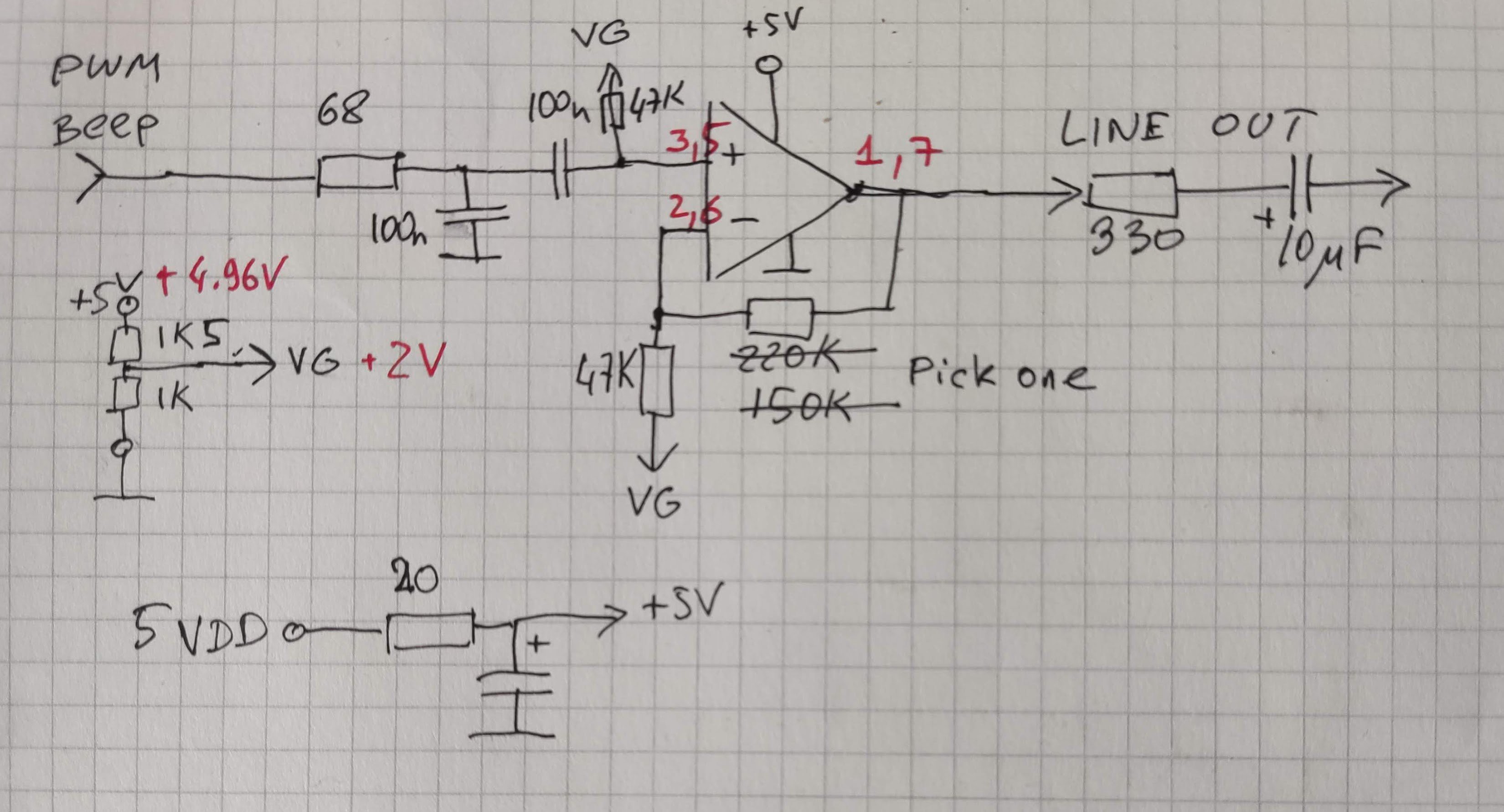
    I might want a little builtin speaker some time later, but for now I just wanted a nice buffered output where I could plug my active speakers without fearing too much of sparkles going up delicate 1.8V I/O lines. So I came up with this fairly basic circuit.

    The input is 1.8V GPIO (pins 80, 79 on Tang Nano 9K).

    The opamp is LM358. There's a passive filter that doesn't pass high frequencies into the amplifier. The gain is set experimentally, I'm still undecided on the value of feedback resistor. Currently it's 220K and it seems to produce levels comparable to what my laptop outputs, albeit a bit quieter. At the same time, they swing wider than what "line out" standard dictates. At the same time, 1 + 220/47 = 5.6, seems that the gain here is a bit high.

    My USB hub that I tend to use for debugging seems to add a horrible bit of extra noise in the power lines, so I have a basic 20 ohm / 100uF filter on the 5V line. Not the ideal way of dealing with this, but it removes a lot of annoying hum.

    The signal part of the circuit is repeated twice for stereo output. AY mix used in vector06cc is L=C+B R=A+B. The 8253 and beeper output are always mono. Stereo AY sounds neat as it turns out.

    I still have many questions and I may need to revisit this circuit later.

  • New parts: USB keyboard to serial adapter and audio codec

    svofski06/27/2024 at 22:34 0 comments

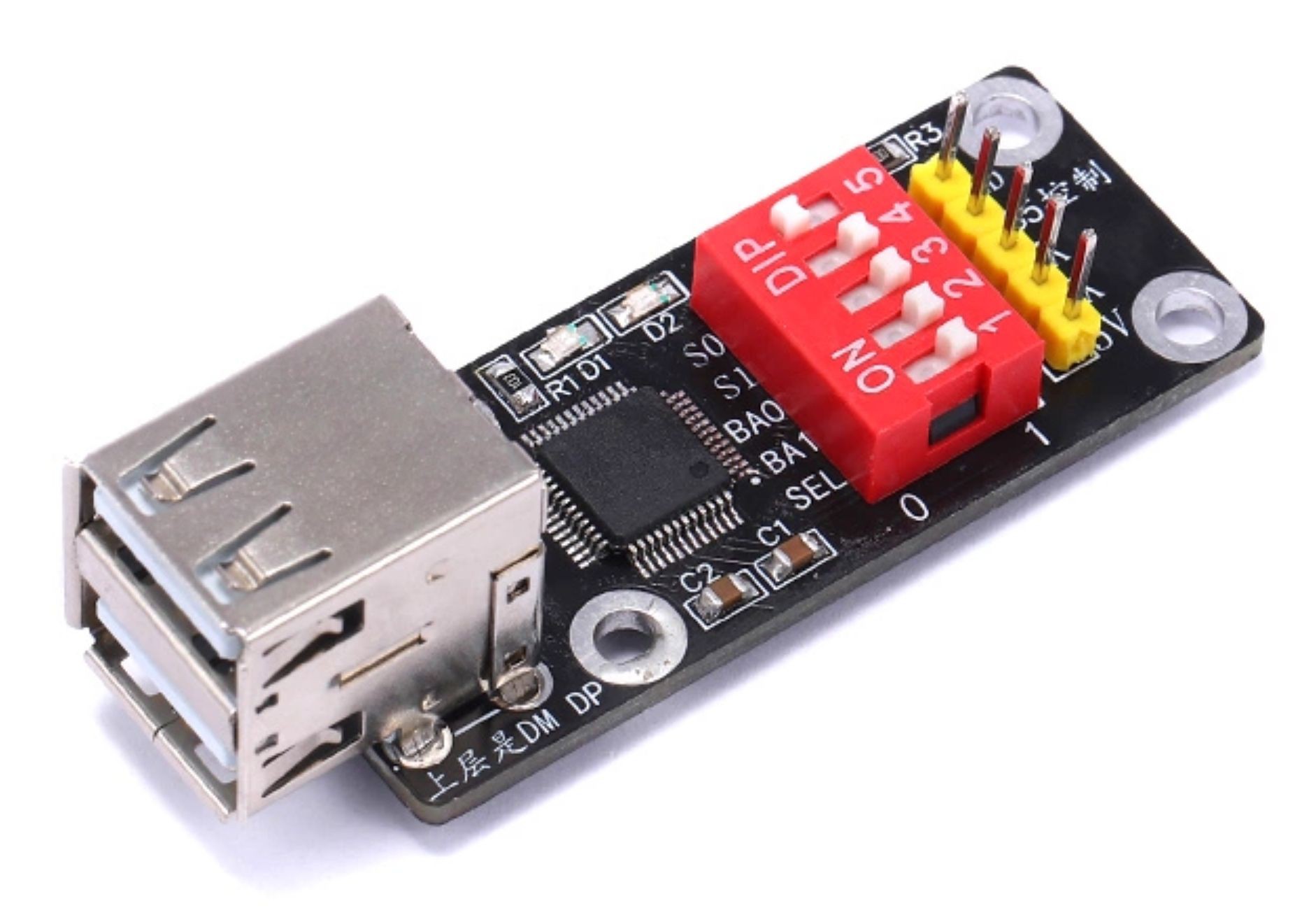
    Two useful parts have arrived. One is a USB keyboard to serial adapter. The keyboard (and mouse) host looks like this:

    Keyboard mouse scanner gun to serial port HID to serial port module CH9350 module KVM extension synchronizer

    It uses CH9350DS to do the dirty job of being a USB host to the mouse and keyboard and converts their output to scancode data on a serial port. Rather nice if true. The documentation is hard to decipher. Here's a link to a copy of the PDF: CH9350DS-Qinheng_KL-024-0000864.pdf There are DIP switches to select baud rate, also the function of two of them is to "set the state" whatever that means. There are only 32 combinations so it should be fine.

    If the docs are to be believed, the output serial levels are 3V3 so that's nice.

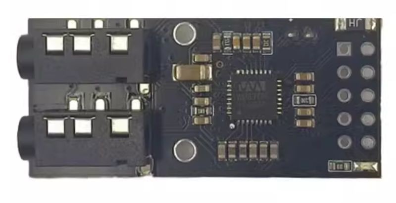
    The other part is a WM8978 audio codec. It's a neat little board (or an MP3 learning pole, apparently) that looks like this:

    WM8978G audio module mp3 music player I2S audio decoding development MP3 learning pole WM8978

    Unfortunately input and output jacks are not colour-coded. There's also a little microphone soldered from the opposite side for some reason. I don't really think it would be very useful in a vector-06c, but we'll see, maybe we can tape load over-the-air.

    The codec chip is a bit more advanced than I need for this project. I could easily get away with a 1-bit sigma-delta DAC, but this board also provides with  a nice pair of 3.5mm jack connectors so it seemed like a nice thing to have. The datasheet is rather intimidating though. I've found a couple of projects with initial setup code that I hope would serve as a reference.

    The datasheet link: https://www.mouser.com/datasheet/2/76/WM8978_v4.5-1141768.pdf

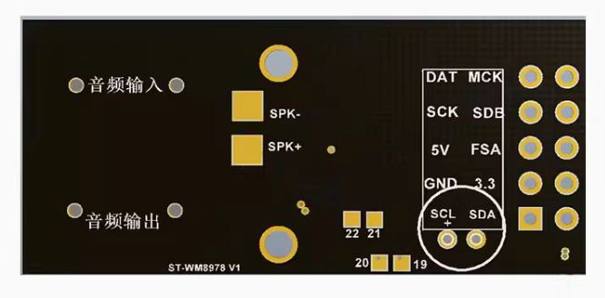
    The pinout is labelled from the reverse side, but you can't see it fully because of the microphone, so here's the pinout picture:

    Connectors on the left: Audio input (top), Audio output (bottom)

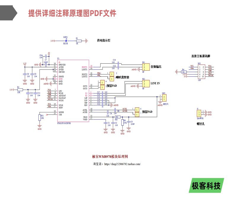
    It's also a rare case when a schematic is available, so here it is:

    I have not yet tried any of these boards.

  • Goodbye T8080 and 65c02, hello vm80a and neo430

    svofski06/05/2024 at 20:00 0 comments

    Preamble

    vector06cc relied on existing CPU cores. For the main computer it was the good old T8080 by MikeJ, which I fixed in a few places to work as a proper 8080 back in the day. For the floppy emulation I used 65c02 by Peter Wendrich. Both are excellent cores and they worked well. However I started noticing instabilities when building my project for Tang Nano 9K. The problem is that the chip was over capacity, and Gowin tools start to behave unpredictably when this happens. I needed to free up some floor space. For example, a perfectly working floppy subsystem stops reading SD card when I add a sound chip. Or the main computer can't exit reset state when I add a floppy. And it's different every time. It's impossible to advance when things turn up like that.

    Disclaimer: I don't know how to properly count the size of synthesized cores, but Gowin Floor Planner shows a number next to each module which seems to represent occupied resources well. I'll call them simply "units".

    As good as these aforementioned cores are, they seemed pretty big on the floor. T8080 around 1800 units and 65c02 around 1700. Back in the day (around 2008) there weren't many alternatives. Today we have more choices.

    Main CPU

    As for the main CPU, there is a brilliant die shot reverse engineered kr580vm80a by Vslav: https://github.com/1801BM1/vm80a It was many times proven to be accurate, so it was time for me to adopt it for vector06cc. vm80a is an interesting model because it follows the original design closely, so it needs two phase clocks like the original. The changeover procedure was relatively painless and the new core worked almost right away. The difference on the floor plan was amazing: 1800 down to 860. This created some elbowroom for the fitter to work, but I needed more.

    Floppy CPU

    vector06cc uses a second CPU to read floppy image files from an SD card and feed the data to a WD1793 floppy controller emulator. It also provides OSD interface to select disk images and provide some control of the system.

    The floppy CPU is 65c02 originally, which synthesizes to 1700 units, which is too fat for a helper CPU. First thing, I updated it to Arlet's 6502 Verilog model. I already did that before for https://github.com/svofski/vector06c-lesshadoks The replacement wasn't all roses, but eventually I managed. This core compiles to around 1100 units, which is much better than 1700. Because this service CPU can be changed to anything, I looked around for other options. These days everyone is supposed to be a fan of RISC-V, but I found it difficult to do on this occasion. They are perhaps compact compared to other modern 32-bit cores, but they tend to be overspecified for my task. SERV is a really interesting option, but I think it wouldn't perform great at my comfortable 24MHz clock rate.

    One of the considerations for making a choice of the floppy CPU was also the code size because BRAM is at a premium. 6502 is an amazing CPU maybe, but compiled C code for it is not the best. I quickly built my emulator code for potentially available CPUs:

    6502 (cc65)
    14891Arlet's 6502
    baseline
    8080 (z88dk)
    16449light8080
    msp430 (gcc)
    9184
    neo430a clear winrar
    avr (gcc)
    10688avr_core_v14 can't really remember which AVR core I tested
    zpu (gcc)
    14445zpu-avalanchecouldn't link but added up object code sizes

    light8080 is very compact, but it's not better than 6502 at running C code. avr is good, but avr cores that I found were not smaller than 6502 and they looked intimidating. I had some hopes for ZPU, but the model that I found wasn't easy to use as well and the code size didn't impress me at all. The compiler is also a bit difficult to set up.

    msp430 code size impressed me. But most of all I was impressed by the size of the neo430 CPU core, it was just around 600 units! (* 632 in the current build) The only inconvenience is that the author decided to arrange it as a complete enclosed SOC, like as it were a microcontroller in an FPGA. This is probably great for some...

    Read more »

  • Vertical scaling

    svofski04/28/2024 at 09:00 0 comments

    This was a big update which hackaday bloody engine screwed up and failed to save. I understand it's a rebel site and it can't be all rosy-pop bubblegum happy, and I appreciate the service anyway, but nnnnggggggghhh!....

    Anyway, implemented some bearable vertical 3:5 scaling so that the entire visible height of v06c screen area fits in 480 lines available on my LCD. Input data: TV-like picture, 312 lines. For VGA we do scan-double and hope that the TV/monitor somehow stuffs it up in a kind of PAL 752x568 mode. Here I don't have that, just a raw LCD glass so I need to scale it myself. Visible line count = 16 + 256 + 16 = 288. 288 * 5 / 3 = 480. This is how the numbers came to be.

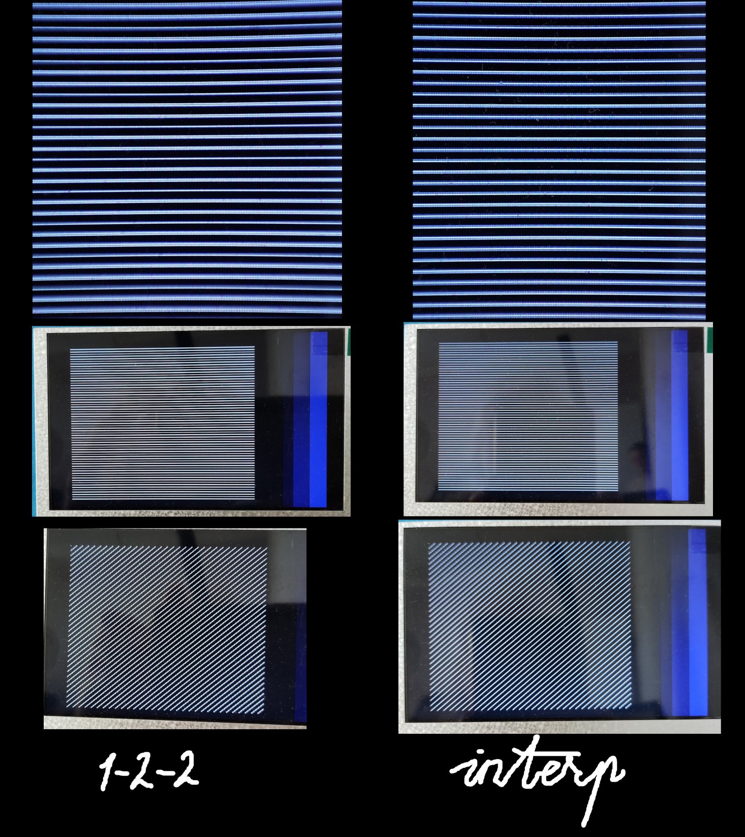
    Left: simple 1-2-2 repeated lines, right - a slightly broken due to physical limitations linear interpolation. It's easy to tell that it exists using tests, but otherwise it's quite good. By the way, it's difficult to capture this difference on a phone camera, which I believe uses its own anti-moire filters that make everything look more or less okay. Real-life difference between the left and the right pictures is more obvious.

    Some trick that I'm using: for every 3 source lines (TV-speed lines) I need to produce 5 LCD lines. So it's not a simple scan doubler. And I found that I can simply skip 6th line on the LCD. It works. But it breaks something in its glassy brain, so you need to feed it with more HSYNC pulses later. If you don't it will skip VSYNC and you'll be only getting even frames, and the liquid crystals will twist too far and there will be image retention artifacts.

    My theory is that in proper scan mode, it twists/untwists them in opposite direction. If you somehow miss the frame, it continues to twist them in the same direction. Would be interesting to find out more about this. I had the same kind of artifact on ESP32S3, but there I had little control over the scanning process and I think it was always overtwisting. At least it was very prone to image retention.

    Proper interpolation would require some real maths. I simplified things a little bit. When computing 5 vertical pixels, every pixel is a sum of 4 terms. So by altering which source pixels go in I can adjust their relative weight. I distributed 3 input pixels evenly, so e.g. 7+7+6 and that's it. The actual code looks like this:

    pipmix4 ma1(clk24, rc_a[0], rc_a[0], rc_a[0], rc_a[0], bmix[0]);    
    pipmix4 ma2(clk24, rc_a[0], rc_a[0], rc_a[0], rc_a[1], bmix[1]);
    pipmix4 ma3(clk24, rc_a[1], rc_a[1], rc_a[1], rc_a[1], bmix[2]);
    pipmix4 ma4(clk24, rc_a[1], rc_a[1], rc_a[2], rc_a[2], bmix[3]);
    pipmix4 ma5(clk24, rc_a[2], rc_a[2], rc_a[2], rc_a[2], bmix[4]);
    
    ...
    
    // pipelined mix = a + b + c + d in 3 stages
    // input components are bgr233, output mix is bgr555
    // s1 = a + b
    // s2 = s1 + c
    // s3 = s2 + d + 1
    module pipmix4(input clk, input [7:0] a, input [7:0] b, input [7:0] c, input [7:0] d, output [14:0] mix);
    
    reg [4:0] rp [2:0];
    reg [4:0] gp [2:0];
    reg [4:0] bp [2:0];
    
    reg [7:0] aq [1:0];
    reg [7:0] bq [1:0];
    reg [7:0] cq [1:0];
    reg [7:0] dq [1:0];
    
    always @(posedge clk)
    begin
        aq[1] <= aq[0]; aq[0] <= a;
        bq[1] <= bq[0]; bq[0] <= b;
        cq[1] <= cq[0]; cq[0] <= c;
        dq[1] <= dq[0]; dq[0] <= d;
    
    
        rp[0] <= a[2:0] + b[2:0];               // stage 0
        rp[1] <= rp[0]  + cq[0][2:0];           // stage 1
        rp[2] <= rp[1]  + dq[1][2:0] + 1'b1;    // stage 2
    
        gp[0] <= a[5:3] + b[5:3];
        gp[1] <= gp[0]  + cq[0][5:3];
        gp[2] <= gp[1]  + dq[1][5:3] + 1'b1;
    
        bp[0] <= a[7:6] + b[7:6];
        bp[1] <= bp[0]  + cq[0][7:6];
        bp[2] <= bp[1]  + dq[1][7:6] + 1'b1;
    end
    

    Resolution:

  • 8x ramdisk

    svofski04/19/2024 at 20:08 0 comments

    One expansion that's a must for every Vector-06c is a 256K ramdisk, colloquially known as kvaz (quasi-disk). It's in fact a ram expansion which presents itself as 4 64K pages of stack-addressable ram. Part of each 64K page can also be mapped as a 16K window in screen space area. A common improvement to this disk is a so-called Barkar Extension, which allows opening extra 2x 8K windows into 64K address space, thus making 128K of 256K directly addressable.

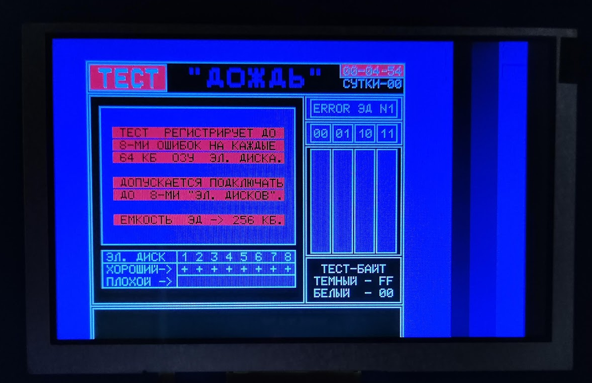
    A common v06c would have one such attachment. However with some craftsmanship, two kvazas can be used with one machine. They would map to the same address space and be configured via separate I/O ports. However, there exists one test program that can simultaneously probe 8x kvaz, making up a total of 2MB of RAM. Unfortunately I don't know of any software that would make use of such a vast amount of memory, except for the test itself. Take note that even just zeroing 2M is a pretty serious undertaking for a 8080-based computer.

    With 32x2Mbit PSRAM available on the FPGA chip it would be a crime not to support this feature (and with a lot of room to spare), so here we go.


View all 28 project logs

Enjoy this project?

Share

Discussions

Similar Projects

Does this project spark your interest?

Become a member to follow this project and never miss any updates