
 svofski
-
Capstanless tape drives revisited
09/05/2026 at 10:27 • 0 commentsThis is about Tapeshnik. My slow-burn project that I'm working on for literally years, but most of that time it's just resting in a box, waiting for inspiration or parts.
Here's the latest video from the series.
The idea is to make a fun-looking data drive that would be something you could find in a late 70s or early 80s computer. Maybe with random access. And with the spools doing fun things. And so that you could build 4 of them and run mergesort. Anyway...
I started with a commercially available tape mechanism and developed some test program to read/write data. Those mechanisms are cool for a while, but then you realise that they still have belts, even the new ones are actually old, they can be hard to buy. Not that you need many in your life but there's grave digging and then there's grave digging. Also their command-wheel / solenoid control scheme is incredibly clever but slow and I don't think it's designed for random-access-tape kind of abuse.
Notes on the first design:
https://github.com/svofski/tapeshnik/blob/master/docs/NOTES.md
I grew bored of that version too soon and switched to developing a custom mechanism. I was inspired by some streamers from the 70s.
* TU60 DECassette https://gunkies.org/wiki/TU60_DECasetteTape_Transport
* TEAC MT-2ST https://oldcomputer.info/media/teac/index.htmThere are also older versions of TEAC data recorder that have slow data rates and tape travel speed.
These drives are interesting because they don't have a capstan. They use biphase mark encoding, which is "self-clocking" to some extent and they are relatively insensitive to some variations in tape speed. Something I could try and replicate myself.
Notes on the second design:
https://github.com/svofski/tapeshnik/blob/master/docs/FUTURISTIC.md
To summarise my story so far: not so easily. My expectations of using SimpleFOC with BLDC motors on two spindles were probably inadequate. I can achieve a pretty stable general velocity, but the detonation/wow/flutter are terrible. And I think this happens because my hub motors still have cogging, there's no mass to smooth it out. The tiniest cogging at the axle gets amplified by the radius of the spool times 2 and this becomes a very funny space chipmunks audio filter if you try to listen to it.
When I came to that conclusion last time I sighed, carefully put the project in its home plastic container and stashed it away. The old time drives used massive motors with analog control so they probably were free from this problem.
I'm writing this because I'm getting some new inspo from yet another forgotten capstanless gem:
* HP 82161A Digital Cassette Drive https://literature.hpcalc.org/items/2150
It's yet another capstanless drive, technically random access. And it only has two motors and a clever analog control circuit, which is documented in this brilliant service manual. It's worth a read even if you don't care about analog electronics, tape or calculators. Just get a breath of old school engineers' spirit.
New ideas
I still don't know what to do about my drive though. I don't think I'm ready to switch to analog control like 70s HP. I have several paths to explore:
- just ignore flutter and use slow super resilient encoding. after all it's a toy and I don't need to achieve high capacity or speed
- add a second clock track, compensate the flutter. I have a 4-track head.
- what if the control loop is just slow and can be tuned up?
- I use one rp2040 to control 2 motors, this could technically be a problem for SimpleFOC.
- also there is no current sensing, only magnetic position sensor AS5047: 14-bit sounds good, but it could be slow and readings can be skewed by misplaced magnets for example. SimpleFOC community seems to be skeptical about magnetic digital sensors for sensitive applications.
- use massive flywheels and belts to even out the flutter
If you're reading this and have ideas don't hesitate...
Read more » -
Flat CRT display and pico-zxspectrum
12/10/2024 at 09:00 • 0 commentsI'm not yet sure what role the pages fulfill, let's see. This is like a blog post.
I bought a doorbell CRT monitor. It's a flat CRT that was frequently found in intercoms and doorbells in the noughties. 4-inch, black and white and it's flat -- similar to what was used in Sinclair's pocket TV and maybe some other ancient portable television sets.
I'm not at all original in this, they were featured by many popular youtubers before. However there was nothing in my household to test it with, so naturally I started looking around for some projects that I could try with one of the dev boards that I have. Found some ESP32 options first, but they were fairly old and didn't build right away so I put them aside. I also had some pipicos lying around.
So the first thing that I found and built is this amazing pico-composite-video:
https://github.com/alanpreed/pico-composite-video
There's a project and a tutorial and a whole Pong game. I have built the pong and we enjoyed a couple of days of ponging with the family. But you begin to feel the limitations of a pong sooner or later...
The next thing I've discovered is fruit-bat's pico-zxspectrum:
https://github.com/fruit-bat/pico-zxspectrum
It seemed amazing and very portable, something you can use with literally just a couple of wires plugged into anything. Just the thing that I needed.
Turns out it could be plugged into literally anything, except for a composite monitor.
Well, not a problem! After some experimentation. And then more experimentation and then some.. I've got this. A ZX Spectrum with a tiny, slightly geometry-challenged B&W display, with a fresnel lens to compensate for its minuscule size:
Hopefully my changes will be the beginning of composite video support for pico-zxspectrum.
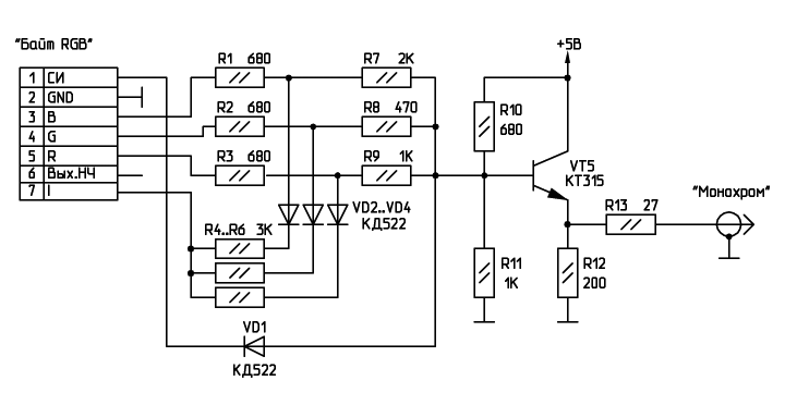
In order to make grayscale from RGBI that the Spectrum produces, I used a circuit from this page
https://zxbyte.ru/byte_connection_to_tv_and_monitors.htm
![]()
I didn't have the amazing KT315. Instead I had to use a mundane SS8050. Maybe because of this, or maybe because the input levels are different, the transistor tends to saturate and it produced smears after longer stretches of bright colours. I helped it by adjusting R11 to something much lower than 1K. It's a mess of wires so I can't really tell the current value, but it's significantly lower than 1K. I'm also not sure if this circuit is really safe to use with 5V power, but it works for me. Maybe it can be improved to be powered from 3V3.
For the reference, the CRT connection diagram found somwhere on Aliexpress:
![https://ae01.alicdn.com/kf/S7e595684c2294ee3814c1517beb10955w.jpg]() I did not have a potentiometers handy so I picked some semi-random fixed resistors. The display is very forgiving and most everything within given values will work. But to get the full dynamic range for a given input signal it's best to find some real trimpots.
I did not have a potentiometers handy so I picked some semi-random fixed resistors. The display is very forgiving and most everything within given values will work. But to get the full dynamic range for a given input signal it's best to find some real trimpots.
My Pages
 I did not have a potentiometers handy so I picked some semi-random fixed resistors. The display is very forgiving and most everything within given values will work. But to get the full dynamic range for a given input signal it's best to find some real trimpots.
Things I've Built
Motöri The Plotter
https://caglrc.cc/motori/
Projects I Like & Follow
 Martijn
 Nicholas LaBonte
 ekaggrat singh kalsi
 Andrew Tudoroi
 Vitalii
 Michael Gardi
 Prashant Sinha
 Michael
 Jeroen Brinkman
 techiemoore
 Mithilesh Gupta Konda
 Bohan Xu
 mircemk
 Zimm
ZimmShare this profile
ShareBits


I like your 'flat' screen CRT stuff. I bought a few of these for monochrome computers like the ZX81. I have not tested all of them yet, I hope none are dead and a waste of money. The small ones are okay for seeing faces but computer text is hard to read.

They are not great for a daily driver computer screen. Even at ZX spectrum resolutions they're a bit blurry. I bought some colour plexiglas filters to improve on contrast, but I dismantled that project. They're waiting for inspiration.
I think yours should be fine, they were a mass market thing after all. The quality of mine seems very good.

Wow thanks for your continued acknowledgement of my work most recently my DEC Precision CRT Display Type 30 Reproduction project.

Hi Svofski, thank you for liking and following the #1 Square Inch TTL CPU ! You might also be interested in the #Isetta TTL computer that can also run ZX Spectrum games.
Appreciate the like forTrekulator - Where No Maker Has Gone Before.

Thank you for liking and following my #Homemade Floating Point Interpreter for 6502! Recently, I used this interpreter to display the coordinates of a telescope control. The size of this application program text is about 5 kB, which is about the size of the program I was able to write back in the 1970s, when computers had only about 4kB-16 kB of RAM.
Thank you for your interest in my Commodore CHESSmate Reproduction project.
Thank you for liking and following my 2:3 Scale VT100 Terminal Reproduction project.
Thank you for your interest in my MCM/70 Reproduction project and following me.
Thank you for liking and following my #PERSEUS-9 homemade mobile 6502 computer! It has been a year since this computer was built. It is working properly.
It's a beautiful build. You have amazing skills and excellent taste.
Thank you for liking and following my #PERSEUS-9 2023 Update! I summarized the development contents that improved the completeness of this computer system during the past year.
Your projects are fantastic, a great inspiration. Thank you for sharing!
Thank you for following and liking my #6802 Serial Terminal !
Thanks for reading my story of the #Ancient 12 hour display It's still shining away and could outlast me. 🤗