ekaggrat singh kalsi

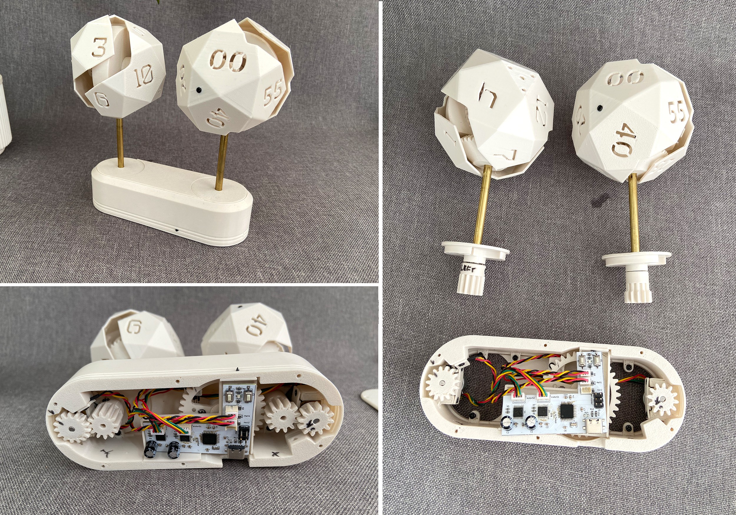
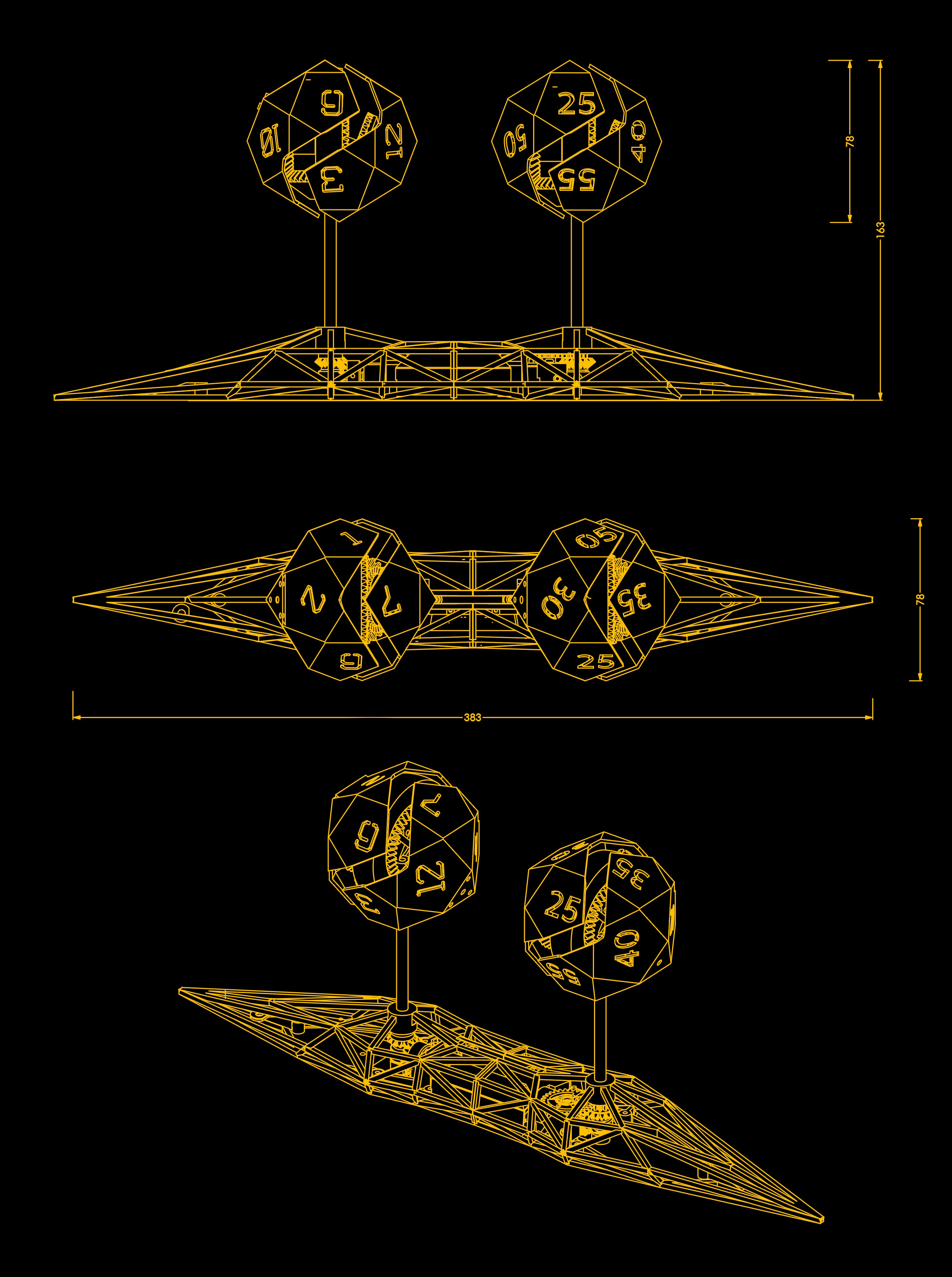
The clock consists of two icosahedron balls . The hours ball has 12 sides with 12 hours and the minutes ball has 12 sides with 5 minute interval minutes. The balls use a differential gear mechanism which make them roll and tumble at the same time. The face of the balls stop at every interval of rotation which is chosen to match the angles of the icosahedron. The hour ball stops every one and a quarter rotation which is 450 degrees and the minute ball stops every 90 degrees which is a quarter rotation. The overall dimensions of the clock are 383 x 78 x163 mm ( 15x3x6.4 inches )
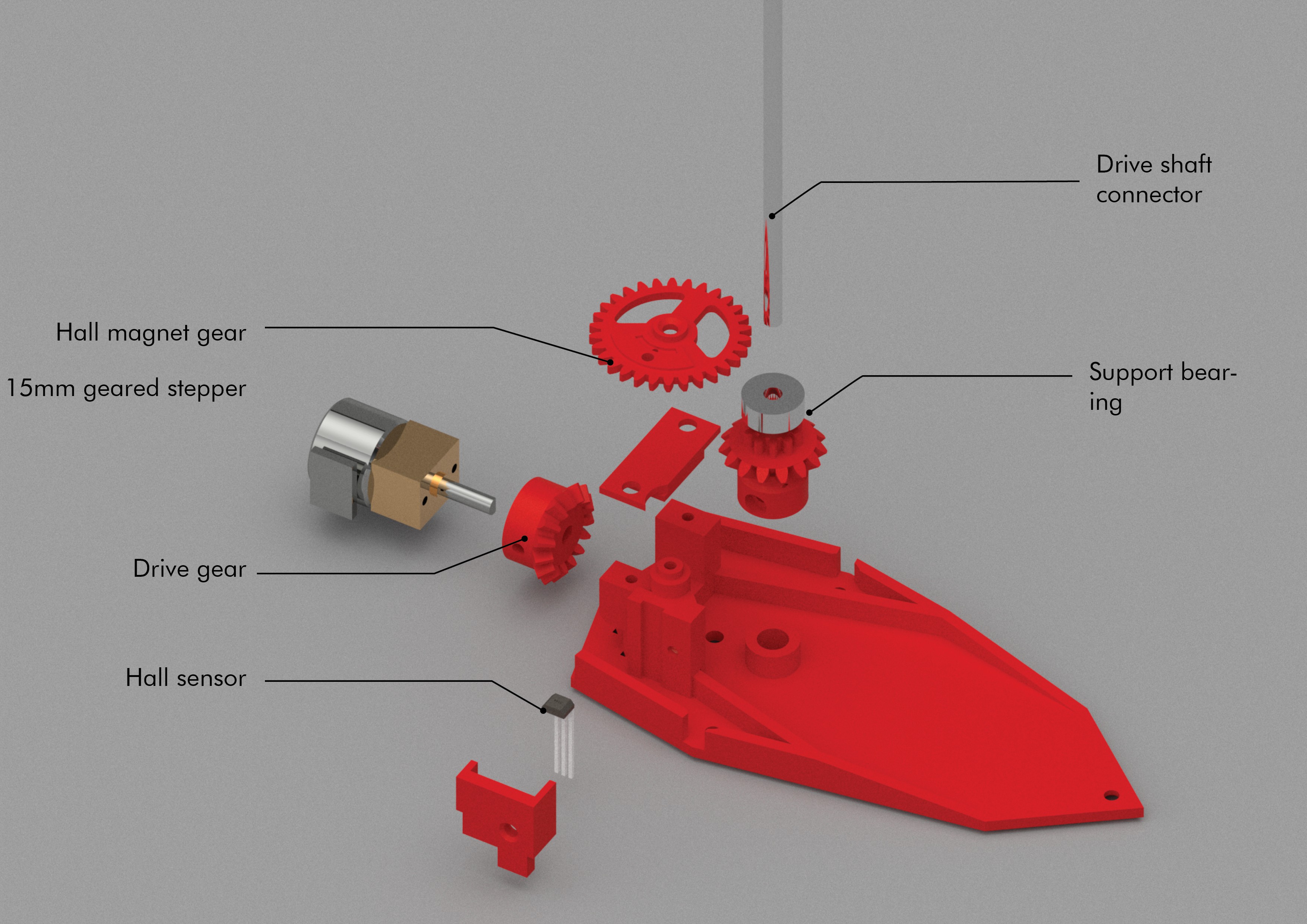
The base has 3 parts . The left and right house the motors and the drive shaft and the center contains the electronics. The motor is a 15mm dia geared stepper motor with a gear ratio of 1:99 . The motor drives a shaft at 90 degrees which in turn drives the balls. The motors find their starting position using a magnet and a hall sensor.
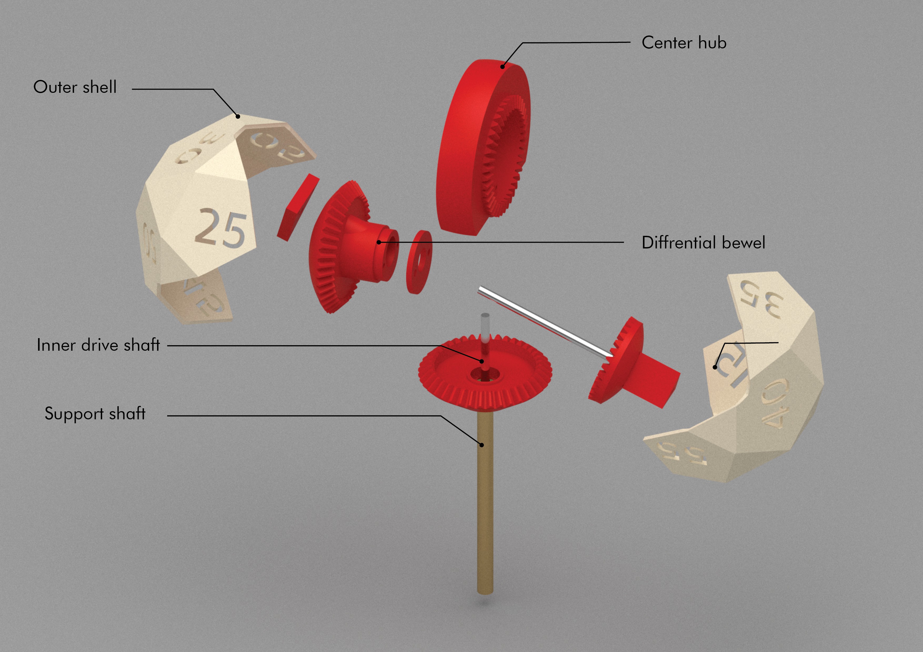
The balls are about 78mm in outer diameter. The central rod drives the central bevel gear which in turn rotates the 90 degree bevel gear on the bottom bevel gear at a 1:1 ratio. The rotation of the 90 bevel rotates the sloped bevel on the main bevel gear at a ratio which makes the ball tumble.
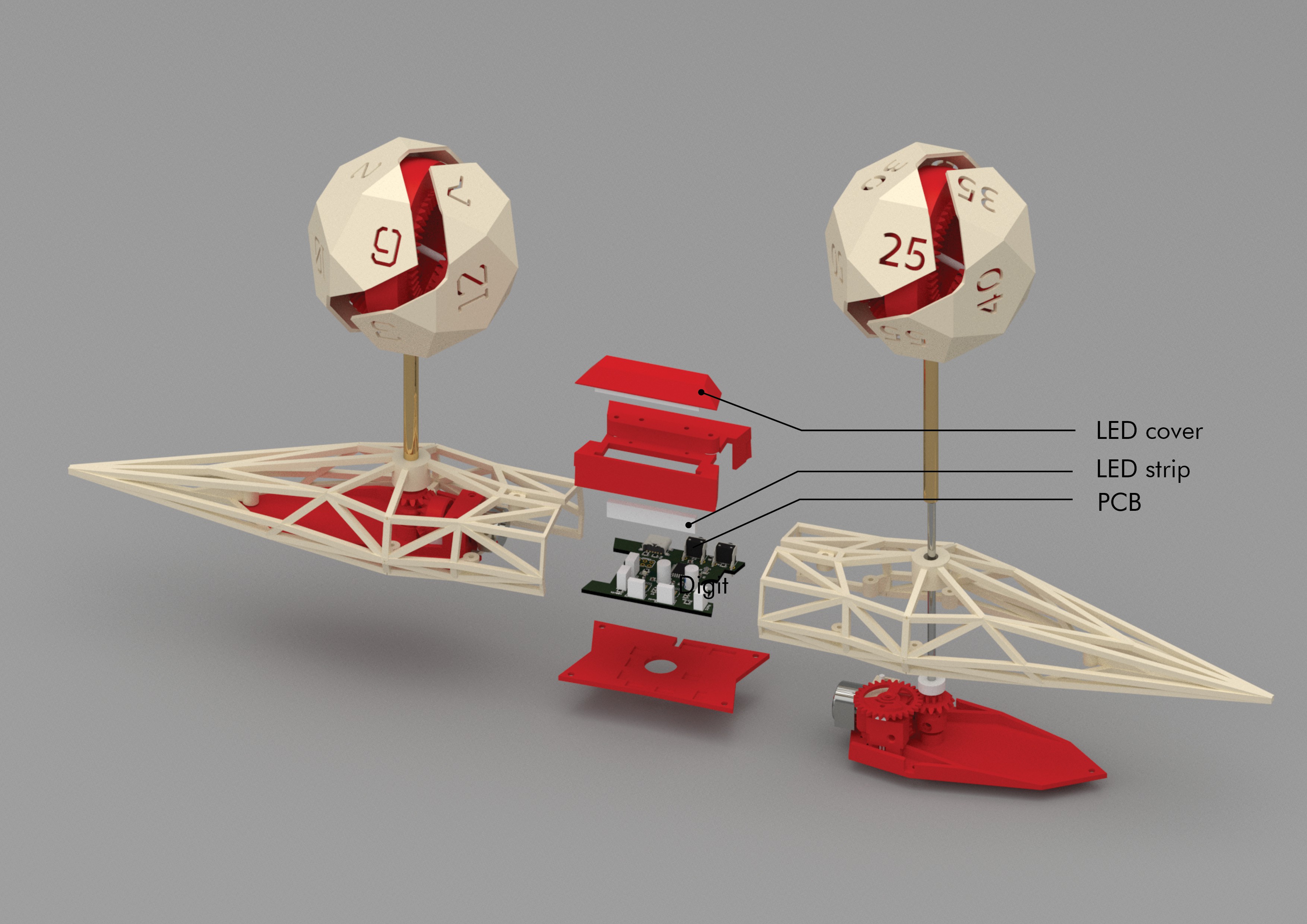
The control board consists of a Atmega 8 running code written in the Arduino enviornemt to drive 2 drv8833 motor drivers. I used the drv8833 as they kept the board small and slim instead of a usual stepstick. Also the motor has a lot more torque in full step mode.
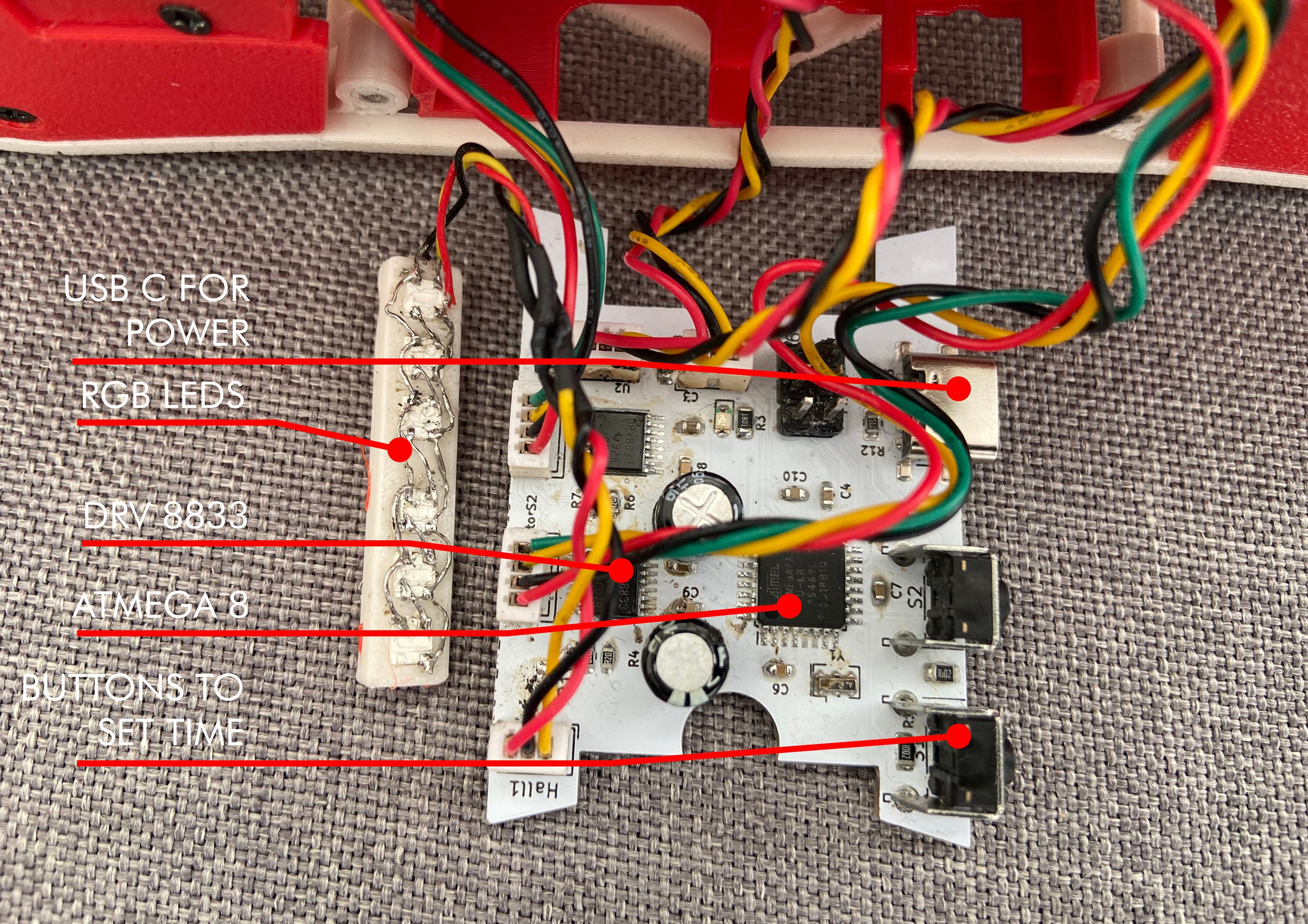
The trouble with the minute balls is that it turns every 5 minutes so to display the in-between minutes there are 6 rgb leds in the center. The leds keep turning on in a sequence as well as blinking and when the last led finishes blinking the ball turns and resets the leds.