Close
0%
0%

6802 Serial Terminal

An RS232C serial terminal using MC6802 & LED dot matrix display modules

Similar projects worth following
In 2007, I made a computer named PERSEUS-3 and start to use it. As a command input and output serial terminal, I had used PC’s terminal software from that days but I began to desire the development of an independent terminal machine that works without a PC in 2018. Its features are as follows.

(1) For a character display, former HP’s dot matrix alphanumeric LED displays were used.
(2) A key scanning, sending characters by serial interface, receiving characters by serial interface and setting to character fonts to LED display module are performed by 6802 single task machine codes simultaneously.
(3) PERSEUS-3 was used as a hardware emulator.
(4) Built in an aluminum die-cast enclosure to make it small and rugged, battery operation is possible.

1. Hardware configuration

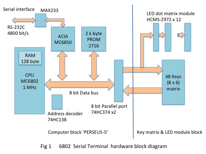
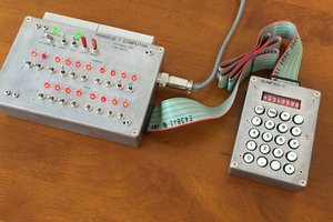
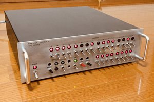
The circuit is made up of two blocks. One is a minimally configured computer block with a 6802 CPU. The other is a key matrix and LED display modules block. An 8-bit parallel read/write port connects the blocks to each other. This parallel port has the same specifications as the parallel port of the PERSEUS-3 6802 homebrew computer

    The schematic is shown in 6802_SERIAL_TERMINAL_schematic_1.pdf

2. Computer block

I chose the Motorola’s MC6802 as the CPU for this computer same as PERSEUS-3. A RAM is used of 128 bytes embedded in MC6802 and no external RAM device. A ROM is 2 k byte 2716 PROM. A serial interface is the Asynchronous Communication Interface Adapter (ACIA) MC6850 (HD6350 Hitachi). Parallel interface to the KEY & LED block is configured with a standard logic 74HC374. I named this computer block PERSEUS-5.

3. Key matrix and LED display module block.

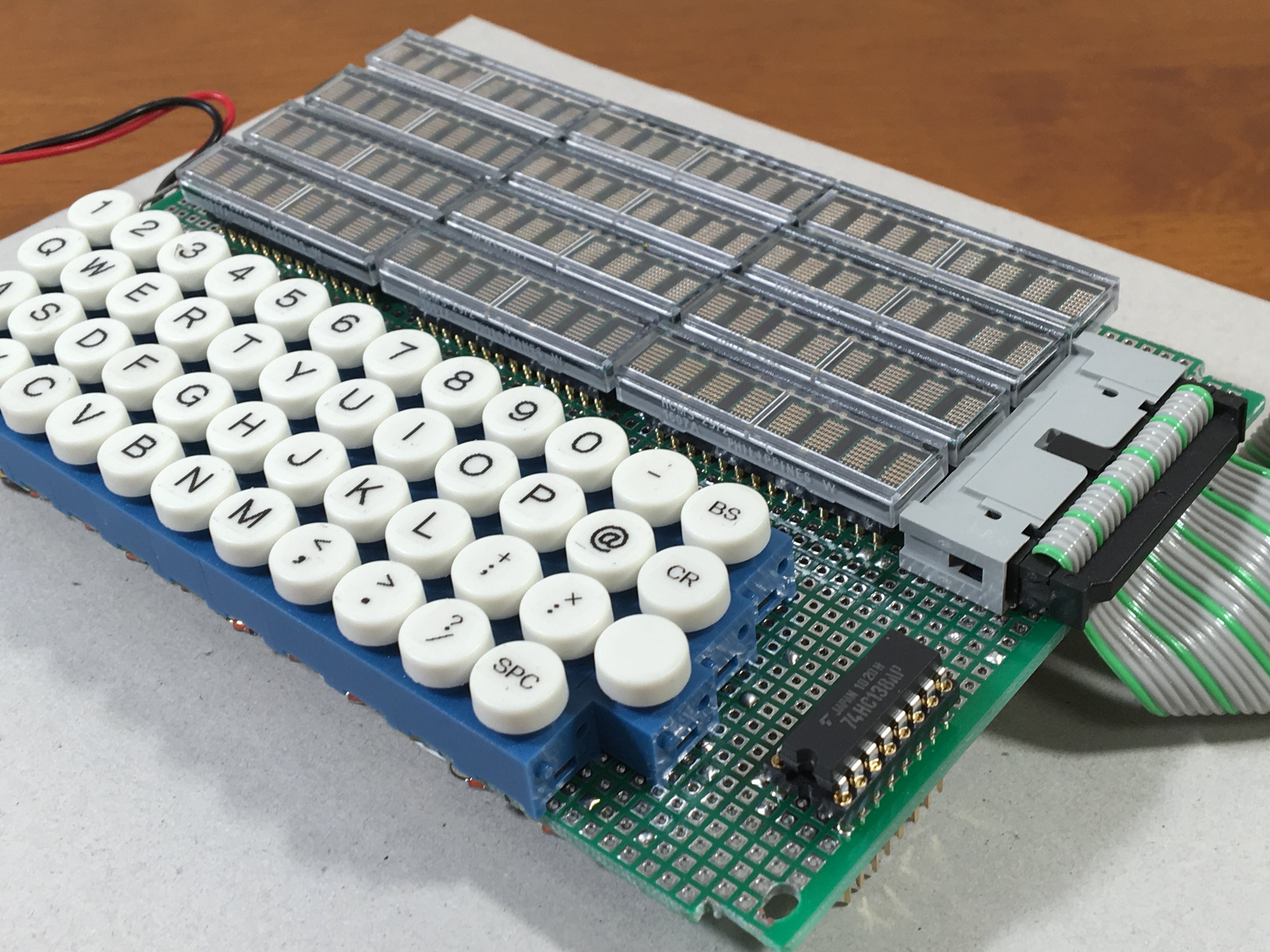
The 48 keys full keyboard is configured 8 x 6 key matrix. Three bits of output port signals are decoded to 6 lines key scanning signal. 8 bits of input port are used to read the key scan result. For the switches, 48 Miyama electric DS-660RC-W(Top color white) pushbutton switch are used.

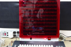
    The terminal has 24 x 4 total 96 characters alphanumeric display. So, 12 LED modules HCMS-2972 are connected by daisy chain. The HCMS-2972 is an 8 characters 5 x 7 dot matrix alphanumeric display. This device requires serial input of character font patterns. For the serial input of the display, 4 bits of the output port of the parallel interface are used. The data obtained by referencing the font table from the ASCII code is serialized and sent to the LED module.

4. Debugging

The assembling machine code is shown in COMMAND_TERMINAL-2_1_0.pdf. The latest version is in the attached file COMMAND_TERMINAL-2_1_1.pdf. As emulation, I connected the key matrix and LED display module block to PERSEUS-3 computer’s parallel interface. I debugged the software on the PERSEUS-3 computer by step executions. After completed debugging, I programmed PROM by using my PROM programmer and implemented to the computer block. Finally the computer block was connected to the key matrix and LED display module block.
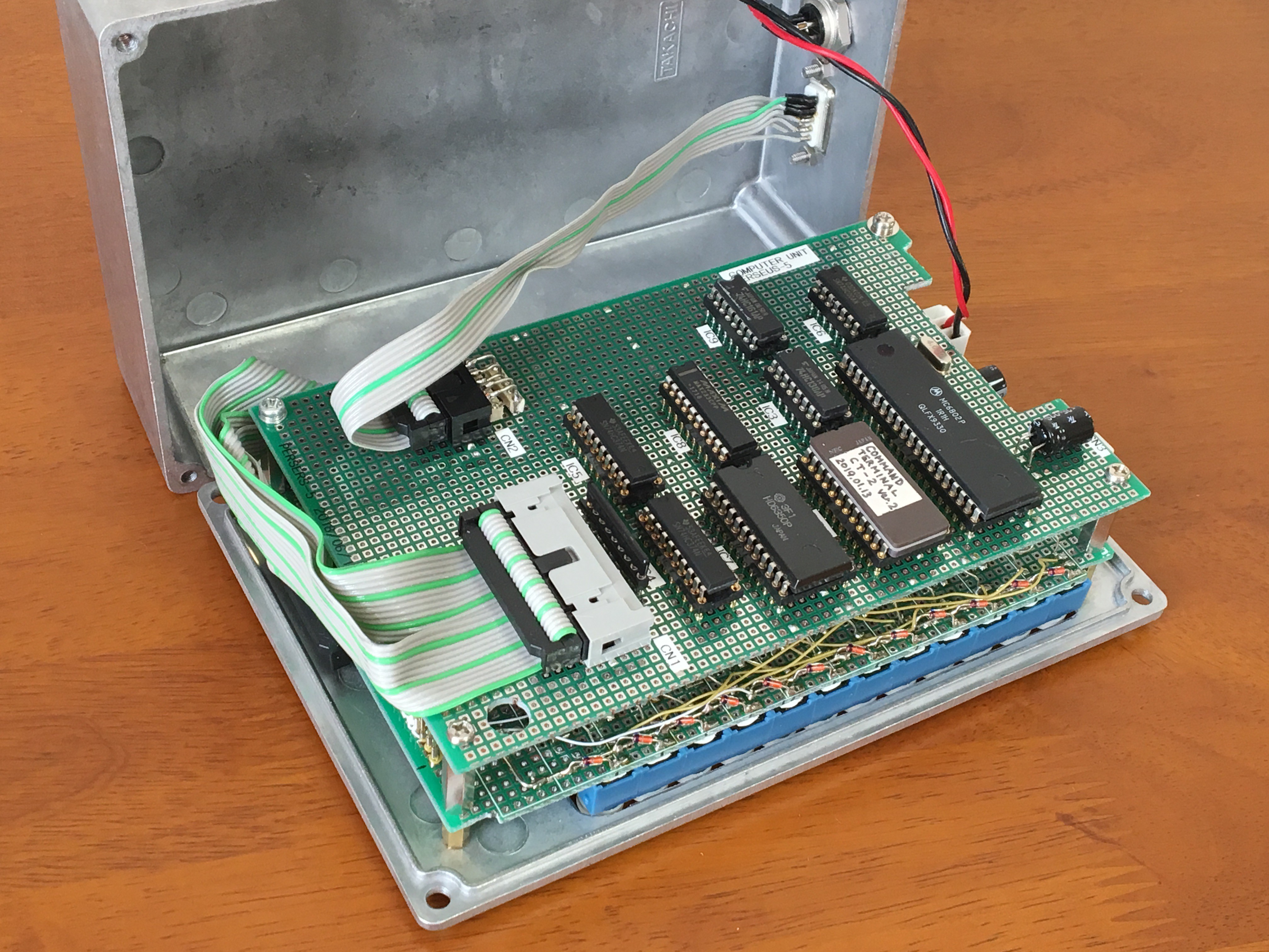
5. Build 

The terminal uses a 18 cm x 12 cm x 5 cm aluminum die-cast enclosure. The key matrix & LED module block and the computer block are stacked in two layers. A power connector is provided so that it can be used with an external battery (1.2 V x 4 ) or 5 V DC power supply.

6. Results

The LED module does not work at all without initialization, so I had quite a hard time until my homemade serial communication program succeeded in initializing it. But this program code was later useful to me when I was recoding the calculator program on my project 6502 Computer runs calculator. The key scan program could also be recoded and used in the 6502 calculator software. 

    In addition, I had a hard time concurrently processing the character input from the keys and the display process of the characters received by the serial interface. The current refresh interval of the display is 0.2 seconds. Therefore, any more number of character displays will be feel delayed in this architecture. So, I struggled some, but I am satisfied with the operation after completion.

7.  Video

    The following video shows the internal structure.

The following video shows the operation of a home-made floating-point interpreter on this terminal. There is no audio commentary, so please turn on subtitles.

Reference: HCMS-29xx Series High Performance CMOS 5x7 Alphanumeric Displays Data Sheet, AVAGO TECHNOLOGIES

(Revised on Mar. 18, 2025)

COMMAND_TERMINAL-2_1_1.pdf

Latest version of assembly code of the 6802 Serial Terminal

Adobe Portable Document Format - 56.99 kB - 03/19/2025 at 03:14

Preview

SERIAL_TERMINAL_FIG_001_1.pdf

Block diagram of the 6802 Serial Terminal

Adobe Portable Document Format - 136.74 kB - 12/07/2020 at 09:51

Preview

6802_SERIAL_TERMINAL_schematic_1.pdf

Schematic of the 6802 Serial Terminal

Adobe Portable Document Format - 254.19 kB - 12/07/2020 at 09:37

Preview

COMMAND_TERMINAL-2_1_0.pdf

Assembly code of the 6802 Serial Terminal

Adobe Portable Document Format - 57.01 kB - 12/05/2020 at 07:34

Preview

  • 1 × MC6802 Microprocessors, Microcontrollers, DSPs / Microprocessors (MPUs)
  • 1 × 2716 Electronic Components / Misc. Electronic Components
  • 1 × HD6350 Microprocessors, Microcontrollers, DSPs / IO Controllers
  • 1 × 74HC00 Electronic Components / Misc. Electronic Components
  • 2 × 74HC138 Electronic Components / Misc. Electronic Components

View all 9 components

  • 6802 Serial Terminal Update log

    Mitsuru Yamada03/18/2025 at 01:39 0 comments

    1. The article was first posted on Dec. 05, 2020.

    2. Revised on Mar. 25, 2022

    3. Revised on Mar. 18, 2025.

         Corrected a typo in the assembly code list.

         Added the latest version assembly code list 'COMMAND_TERMINAL-2_1_0.pdf' to the attached files.

View project log

Enjoy this project?

Share

Discussions

Giovanni wrote 02/24/2024 at 02:00 point

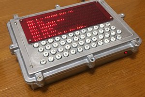
Neat project. I recently saw this 6502 video with LEDs:

https://www.youtube.com/watch?v=upF-8q-hRlw

https://monster6502.com/

  Are you sure? yes | no

Mitsuru Yamada wrote 02/24/2024 at 06:19 point

Thank you for the information. The number of transistors in an 8-bit CPU at this time was about 3,000 to 5,000, so there are people who reproduce it using discrete transistors and gate ICs. I think it is wonderful.

  Are you sure? yes | no

michimartini wrote 05/12/2022 at 21:23 point

Unique, pure and beautiful! Where did you find that contrast enhancing red filter that is on top of those HP-character-dot-matrix displays?

  Are you sure? yes | no

Mitsuru Yamada wrote 05/18/2022 at 09:24 point

Thanks! This is a red colored clear acrylic board sold at a local DIY store. I use clear, colorless acrylic sheets for my Nixie clock projects.

  Are you sure? yes | no

epooch wrote 03/19/2022 at 01:02 point

How do you like the DS660RC key switches? I m looking to build a similar keyboard to this, and these look like a good solution.

  Are you sure? yes | no

Mitsuru Yamada wrote 03/19/2022 at 02:05 point

Thanks! For this terminal, I used 48 DS660RC-W (Top color white) pushbutton switches to create the design I wanted. I also like the feel of the press. I have been using them for 4 years since I made and I like them with no trouble. The chattering of the switches is properly removed by software sampling. In this example, the switches are spaced 10.1 mm apart, but it would be easier to type with a larger spacing.

  Are you sure? yes | no

epooch wrote 03/19/2022 at 04:52 point

thanks for your response! I love your projects. The enclosure designs are all so beautifully industrial.

  Are you sure? yes | no

FozzTexx wrote 12/08/2020 at 17:42 point

I'd love to see a video of you using it to connect to bbs.RetroBattlestations.com!

  Are you sure? yes | no

Mitsuru Yamada wrote 12/09/2020 at 01:30 point

Thanks !

  Are you sure? yes | no

Kn/vD wrote 12/08/2020 at 10:05 point

The display is crazy cool!

  Are you sure? yes | no

Mitsuru Yamada wrote 12/08/2020 at 13:13 point

Thanks! As you can see at the end of the source code, it was a hassle for me to code a pattern with a 5x7 font, but I can create any font I like.

  Are you sure? yes | no

sjm4306 wrote 12/07/2020 at 14:05 point

I love everything from the vintage dot matrix LED displays to the keypad. I wish the LED displays were cheaper and more easily available though, I'd love to put them in many projects if they weren't upwards of $30 a pop. Great job, it's a beautiful build!

  Are you sure? yes | no

Mitsuru Yamada wrote 12/08/2020 at 05:54 point

Thank you for your comment. I like the LED dot-matrix display because it has a feel that LCDs don't have, but the problem is the price. This cost more than 10 times as much as it would have cost to make on an LCD module, but this seemed to be the motivation for me to finish it without giving up until the end.

  Are you sure? yes | no

Wiles wrote 12/08/2020 at 09:06 point

Those displays are beautiful.

  Are you sure? yes | no

Tom Nardi wrote 12/05/2020 at 17:43 point

Absolutely gorgeous.

  Are you sure? yes | no

Mitsuru Yamada wrote 12/06/2020 at 01:38 point

Thanks ! , I think the LED module display is a bit retro and nice, but it was a bit costly.

  Are you sure? yes | no

Similar Projects

Does this project spark your interest?

Become a member to follow this project and never miss any updates