Arno
Arno-
Log 3 : Board Assembly & Sound!
07/29/2020 at 23:57 • 0 commentsAfter finishing the layout for the schematic in the previous log, I ordered a few boards from OSHpark as well as a stencil from OSHstencil.
I cheaped out and went for a polymide stencil. This was a terrible decision since it's so floppy and a stainless steel one is only $5 more.
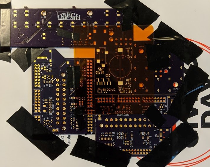
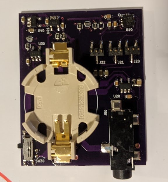
To assemble the board, I went ahead and found some old PCBs from college to lock my target PCB in place with tape. After placing the stencil on top and also taping it down I squirted out some low-temp-reflow solder paste and got to work with the spreader.

The results are... rather poor. There are quite a few pads bridged together, particularly at the QFN footprint & some of the sot23-5 footprints. I believe this happened because a few reasons: I used a floppy stencil. The jig-of-boards wasn't on a very flat surface and thus allowed for some wiggle of the target board. Lastly, I was greedy with my solder paste and only applied very small amounts in localized areas which meant I had to do several spreading passes to get full coverage. Applying a large amount of excess paste to allow for a single spreading action to get full coverage is a much better technique. In any case, these problem areas were pretty easy to fix with a pair of tweezers.
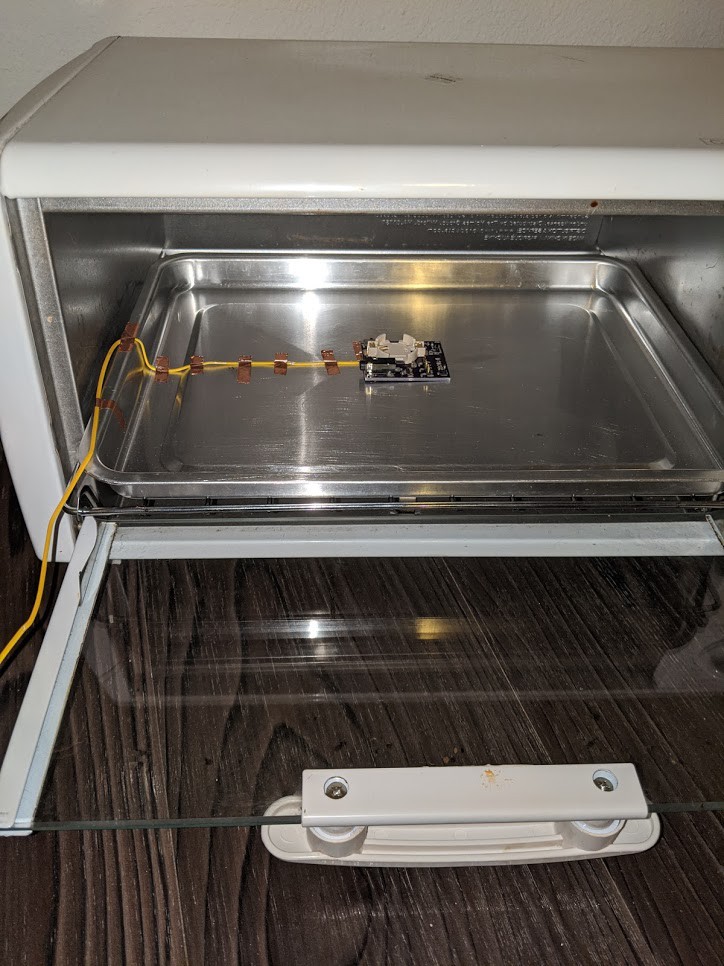
After then placing all of the parts, I reflowed the board in a second-hand toaster oven. Apparently you don't need to follow the exactly specified reflow temperature vs time curve to get decent results. Instead, you can just monitor the board's temperature with a thermocouple and just turn off the oven after reaching the peak temperature specified in the reflow curve.
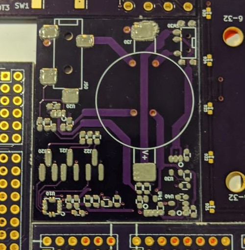
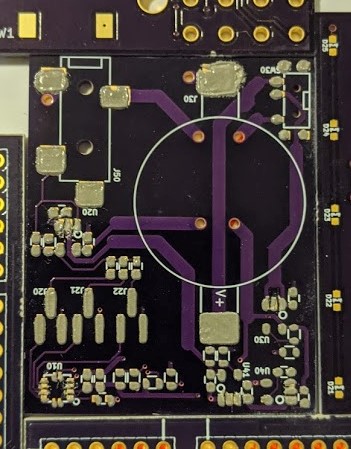
The bake went pretty well... except for that accelerometer! You can see that it's rotated about 30 degrees and that the QFN pads don't align! To fix this, I used a hot air gun to reflow that whole corner of the board and fix. A nicer hot-air gun specifically for doing hot-air reworks, like the ones that Hako makes, would have been much nicer to use. I'm surprised I didn't end up sending all of the nearby passives flying, but this worked out pretty well anyway.
The astute will notice that, in my final assembly picture above, the TLV9001 has mysteriously grown 6th lead. After much head scratching and re-consulting of the datasheet, I realized that I had purchased the wrong part. I had designed for the "TLV9001 DBV" which I assumed was the only part that came in the sot23-5 package. In fact I had accidentally purchased the "TLV9001U DBV" because the right part is out of stock at Digikey. To solve this, I ordered a few "TLV9001S DBV"s since, besides the extra enable pin, it has the same pinout as what I needed for my design. Conveniently the enable pin is next to the positive rail pin, so keeping the part on by hand-soldering a bridge between the two pins was pretty easy. I also employed my favorite rework trick: stacking SMT passives on top of each other. I realized that my summing amplifier applies a |gain| of 1 to each channel. When all 3 channels are summed, there is a chance I can get a peak value of triple the peak of one signal and get a saturated output. So, stacking 3 10Ks in parallel on the feedback resistor pads was an easy way to bring the pass band |gain| down to (1/3) for each channel.
As expected, powering the device from the mic bias did not work. With battery power though, all components operate as expected. After mounting the board to the back of my uke with some electrical tape, I made a quick recording in Audacity.
This signal is pretty distorted because of saturation at the input of the audio codec. After adjusting the recording levels, I was able to record something that sounds a little better.
Unfortunately, there's quite a bit of noise, but I'm happy that it doesn't sound super awful. For now I want to play around with the jumper settings and analyze the differences between the waveforms of the three channels. Then, for a next design, I'd like to properly tackle the mic-bias powering, reduce the form factor (that battery is huuuge), and do a more robust noise analysis/characterization.
-
Log 2 : Rev1A Design
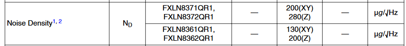
07/28/2020 at 01:21 • 0 commentsAfter creating a proof-of-concept with an ADXL337 from Sparkfun and some conditioning with a breadboard, which was super noisy, I went about putting together a schematic for a small PCB. I ended up choosing a FXLN8361Q from Freescale (NXP). Compared to the ADXL337, it does have marginally lower noise density. On Digikey, the price difference between the two is only a few cents.
I wanted to design something that would meet the following criteria:
- output to a 3.5mm audio cable
- be battery powered
- be mic-bias powered
- cheap
I wanted to output to a 3.5mm headphone jack so that I could plug the device into my PC and record some sounds as either a Line-In or Mic-In source. There is a pretty dizzying array of options for microphone pinouts with TRS or TRRS 3.5mm jacks. A fairly common 3-contact TRS pinout for microphones is [Left, Right, Gnd]. I ended up choosing a TRS pinout with a [mono-output, bias-in, gnd] mapping for simplicity's sake. I threw in a summing amplifier with some 1st order low-pass & high-pass filtering. This allows me to have an AC coupled output with some noise reduction and an output resistance of basically 0 Ohms. The FXLN8361's output impedance is roughly 10KOhm. By interposing some 3 pin 1.27mm headers between the accelerometer and the input of the summing amplifier, I can play around with turning on different combinations of the X, Y, and Z directions.
The second design criterion was pretty easy to satisfy. I chose a CR2032 as it's a relatively common button cell battery that has very good capacity compared to other button cells. Furthermore, its discharge curve reduces from 3V to about 2V when it is empty. In order to maximize battery life, I chose the positive power rail to be a linearly regulated 1.8V off of the battery voltage.
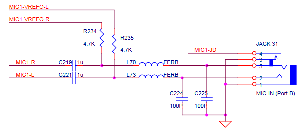
The third criterion was not very easy to meet. Most audio codec ICs can source a very small amount of power from reference voltages that are tied to the input signal lines of the mic-in/line-in connectors via pullup resistors. For example, the Qualcomm WCD9335 that sits in the Pixel 1 phone can source 5uA to 6mA for a mic load. The load regulation & accuracy is seemingly pretty terrible though and the datasheet claims that it can be anywhere between 1V and 2.85V. The current limiting pull-up resistor itself will also effectively degrade the load-regulation. The codec from Realtek that sits on the motherboard of my PC, an ALC887, apparently has an output reference voltage that can be configured for either 2.5V of 3.75V. But, the sourcable DC current isn't specified. Realtek's recommended audio jack schematic shows us what we can expect in terms of a size for these pull-up resistors:
In any case, the FXLN8361Q only consumes about 180uA of quiescent current when powered with 1.8V. The op-amp I chose for some basic filtering, the TLV9001, has a worst case rated quiescent current of 77uA. If the power supply components can all be kept fairly low power, and sufficiently large resistors are used for general pulldowns/pullups and filter components, then the core circuitry should consume < 500uA.
The required negative rail for the op-amp is a linearly regulated output of an inverting charge pump. The inverting charge pump is an apt choice here as it is much more efficient than other switching topologies (e.g. inverting buck) at these low power levels. A charge pump also requires many less external parts which is nice. Since the AC coupled version of the signal cannot be greater than (1/2) 1.8V, it's ok for the magnitude of the negative rail powering the op-amp to be a little smaller than -1.8V. Given restrictions on the drop-out voltage for the linear regulator, I chose the negative rail to sit nominally at -1.453V. The charge pump switches at well above the audible range (30KHz min, 50KHz nom) and the linear regulator following it has a PSRR of about -35dB at these frequencies, so I'm not too worried about switching noise impacting the audio quality. All in all, a quick & dirty spreadsheet I put together indicates that during an active use, the 1.8V regulator will pull about 2mA. This means that, if the codec's bias output is configured for 3.75V, the MIC-bias pullup resistance on my PC's 3.5mm input jack would need to be < 975 Ohms in order to succesfully power the device with the mic bias reference. If the reference schematic above was implemented on my PC's motherboard, and the reference voltage was configured for 3.75V, then the maximum supply current I can tolerate is only about 400uA. I don't have a schematic for my motherboard so I don't know what voltage the reference is configured for or what the pullup resistances are, but my hopes are not high that the mic-bias powering will work. =(.
I was able to meet the cost criterion pretty well. The most expensive part in the design is the accelerometer itself at about $4.6 in low-volume. Somehow, I did manage to splurge a whopping $2.7 on the negative linear regulator - there must be a cheaper LDO that is just as good somewhere. The rest of the parts in the BoM are all less than 1$ a piece and the total BoM cost comes in at about 15$ in LV pricing.The schematics for this Rev1A design, as well as the power calculation spreadsheet, are attached to this project page.
-
Log 1 : Concept
07/25/2020 at 22:12 • 0 commentsMy journey for this project started about a year ago. I had picked up a ukulele as a new instrument to learn in my free time. I had a desire to do some kind novel project outside of work and decided I was going to find some new, unique way of recording the vibrations from a stringed instrument. If I could find some strange, non-traditional method, I might even be able to affect the dynamics of the string's vibrations to create a new sound. Transducers with highly non-linear responses, for example, would enable this.
This accelerometer project though, is a bit of a compromise and is effectively my third concept iteration on the target described above. Though I didn't realize it at the time of coming up with my first prototype of this iteration, I have since found that the idea is not original and has already been applied by several people. Most notably, I found that a few people at Analog Devices, who make several of these analog-output MEMS accelerometers, wrote a paper on the subject. Furthermore, this method is a very close cousin of contact piezo microphones that already exist on the market.I want to talk briefly about the first two concepts because I do think they are interesting and I may want to revisit them someday.
Concept 1 : Optical Fiber Pickup
The idea behind this concept was to replace the strings with optical fiber and then feed them with spectrally narrow-ish-band (LED, not laser) light in CW mode. With notches then cut into the fiber somewhere between the bridge and the fretboard, I was hoping to be able to cause some of the light to exit TIR and transmit down towards the body of the ukulele. By then placing an array of 4 photo-diodes below the strings, I would have the option to either produce a poly-phonic output or a single analog output via a summing amplifier. If I could get the output beam to be sufficiently narrow/low-divergence, then string vibrations should create a proportional, variable irradiance incident upon the photodiode.
Some of the inherent limitations I ran into with this idea include:
- In the prototypes I made, I was unable to create the right type of notch that would cause enough of light to exit TIR in a controlled beam down towards the photodiodes.
- The notch making process I employed was very crude and purely experimental though. Maybe some real optical engineering and some iterative ray-tracing simulations could lead to an optimal notch shape that would allow enough out-coupling efficiency to exit to get a reasonable signal.
- In general, the available plastic optical fiber that I found is not rated for the string tensions required by the soprano ukulele. If the required frequency or required string length is reduced though, the required tension can decrease enough. The required tension increases with the square of the fundamental frequency and linearly with the length. Something like a bass guitar would be more apt for this.
Some other downsides include:
- Even the cheapest LED fiber-coupled transmitters I could find are both bulky and expensive.
- I was unable to figure out how to robustly constrain the transmitter end of the fiber mechanically. The aforementioned transmitter holds the fiber in place via a friction fit with a plastic lock nut. This was definitely not strong enough for the required string tensions.
- To prevent noise from the ambient light from destroying the signal or even saturating the sensor, optical filtering material would be needed to enclose the section of the bridge with the sensors. The most straightforward way would be to use some black material to block the entire spectrum, but a a cooler (and more expensive way) might be to use some kind of material that attenuates only the spectrum being transmitted through the fiber. For example, if a UV light source was used, then plexi-glass could be used since it acts as a longpass filter with a cutoff wavelength near the blue-light to UV-light transition zone.
Concept 2 : Capacitive Pickup
The idea here was to use metal strings sandwiched between two conductive plates. This would form a capacitive voltage divider via the capacitance from the upper plate to the string and the capacitance from the string to the lower plate. By feeding voltage divider with carrier signal (say, somewhere between 100kHz and 1MHz), I was hoping to create an amplitude-modulated waveform by plucking the string. If the string position changes relative to the two fixed plates, then the envelope of the carrier at the output of the voltage divider should as well. Demodulating this output (multiply by a reference carrier) would then allow you to recover the low-frequency audio signal. I was able to confirm that this works in PSPICE with some rudimentary simulations involving signal-controlled capacitor simulation blocks. This is fairly similar to the electric reed organs from the early 1930s that also use electro-static pickups to measure the position signal of vibrating metal reeds.
Some of the inherent limitations I ran into with this idea include:
- The effective capacitance between the plates and the string in the proof-of-concept that I built was somewhere between 100fF and 1pF. This is a huge problem because there are many stray capacitances in the system that far exceed this value. For example, on a breadboard, the capacitance between a two contacts in a signal row is about 5pF. All the extra parallel parasitic capacitance between ground and the live contact ends up destroying the dynamic range of the voltage divider.
- The plates and wires in my proof-of-concept very easily picked up 60Hz signal from the mains. There is probably a way to get around this via some sort of differential design, but I did not pursue it in earnest.
Concept 3 : Accelerometer Pickup
This is the final concept I landed on and is what this hackaday project page is based around. I wanted to simplify and implement something that I would have high confidence in. Since acoustic instruments have large chambers designed to resonate, sensing the accelerations of the outside surface of an acoustic instrument should provide a signal that is proportional to the forces/pressures imparted by the acoustic energy emitted by the strings. This is very unlike an electric guitar, which senses string velocity, and the above concepts 1 & 2, which sense string position. Piezo contact pickups sense the acoustic forces/pressures directly, but their frequency response is not very flat.
One might think then, that this concept fails the original targets/goals that I described at the start of this log; the accelerometer likely won't have any interesting non-linear effects that will fundamentally change the sound of the ukulele. However, there are two things which I hope will pan out into a more interesting study:
The first is that the analog MEMS accelerometers on the market typically output three channels corresponding to three orthogonal directions. Could the relative differences between the outputs of each of these channels encode something interesting worth hearing? Would it be possible to infer the two orthogonal polarization directions of a string vibrating in 3D and is there something interesting, audibly speaking, about the two different polarization states of a vibrating string?
The second is that various ways of mounting of the accelerometer to the instrument might induce different audible effects. For example, could introducing some strange material between the sensor and the body of the instrument create some interesting effects? Furthermore, could slower accelerations that aren't caused by the string's vibration (e.g. instrument movement during playing) create some interesting bass features?
Perhaps the two above items are wishful thinking. In the end though, I really just want to build something and put the design files on the internet.
Accelerometer Contact Pickup
A simple/cheap exploration into sensing audio outputs from existing instruments.