-
SSR
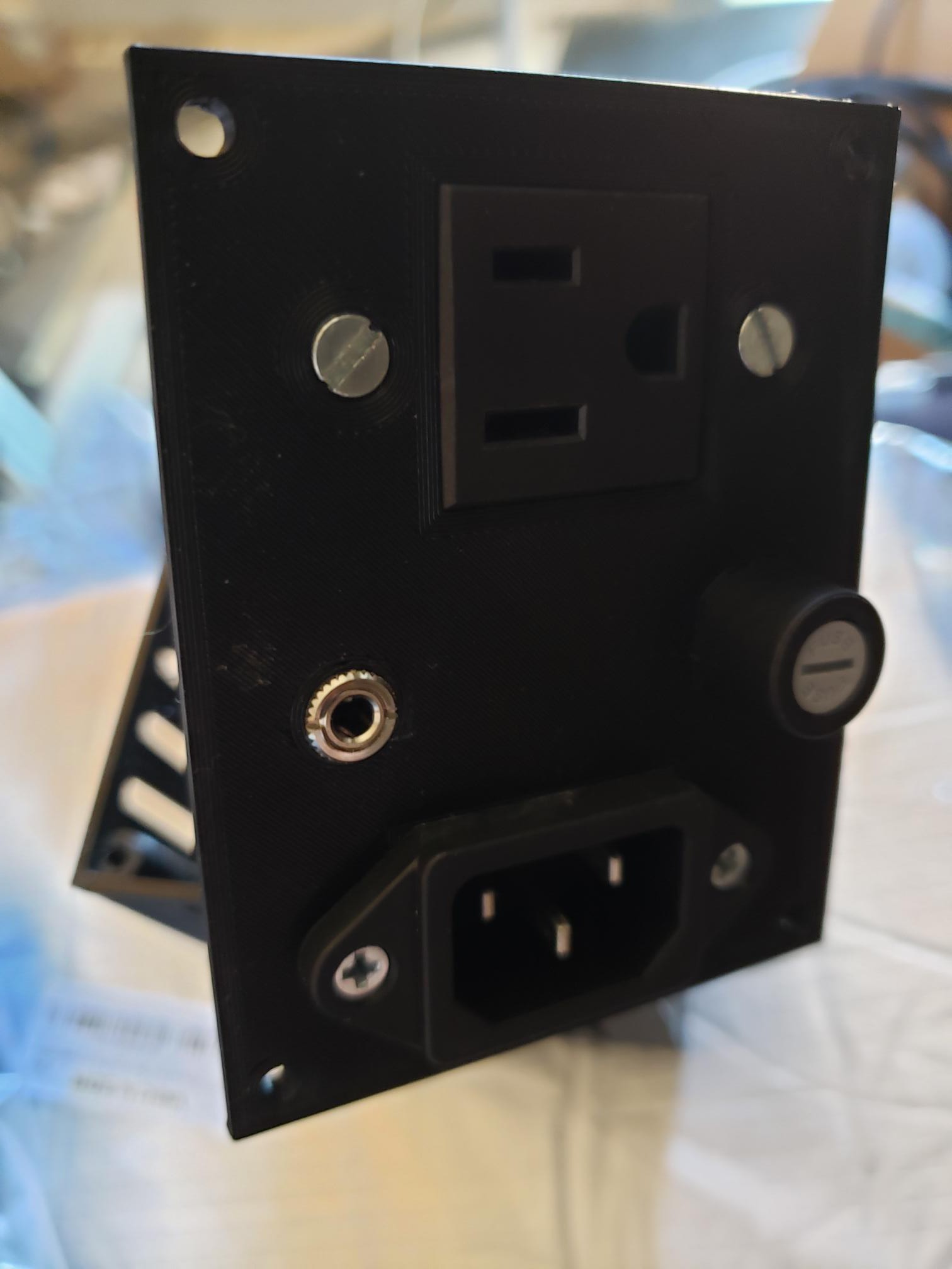
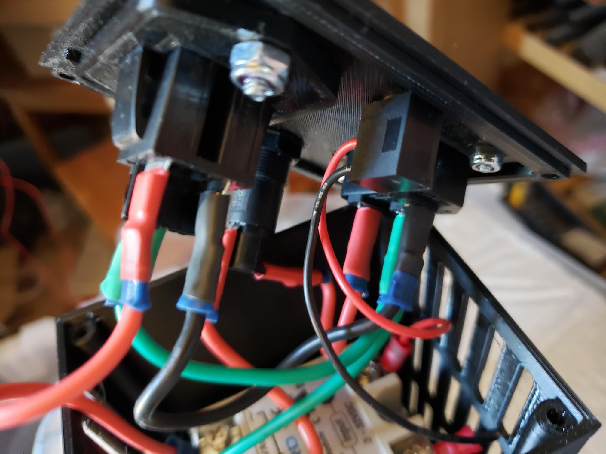
09/14/2020 at 15:41 • 0 commentsThe final piece is controlling the new heated bed. The SSR is a standard 40A unit, which is not needed but the larger SSR and larger heatsink will keep the system cooler overall as it dissipates heat over more area. It's really simple, one outlet, one inlet, one fuse, a 1/8" connector for control voltage and a 3d printed case(the reason the SSR heatsink is so large to not overheat the printed case and get it melty)
![]()
![]()
![]()
![]()
-
Heating Speed
08/03/2020 at 15:48 • 0 commentsThe previous heater would do 22C to 110C in around 12 minutes, usually, but sometimes had trouble maintaining that temperature. Didn't need it often but Polycarbonate liked the heat. But even lower temperatures still took a long time.
Now with the new heater
22C to 100C: 125 seconds
22C to 150C: 211 seconds
So, needless to say, it's way faster now.
-
Insulation and cable cleanup
08/02/2020 at 19:01 • 0 commentsAdded the rest of the insulation. Added a plug to the cord to attach to my SSR box and added the green ground wire which is barely visible under the super fancy woven wire protection. Ready to go back on the printer.
![]()
-
Insulation and Grounding
07/30/2020 at 18:38 • 0 commentsThe bed doesn't really need insulation to get hot fast, but it will prevent the heat from impacting the surroundings too much.
The more important bit is to ground the bed properly. This is an AC heater and may injure or kill you if you are exposed to the voltage. Grounding means that if something shorts out then it will go to ground and blow the fuse/breaker.
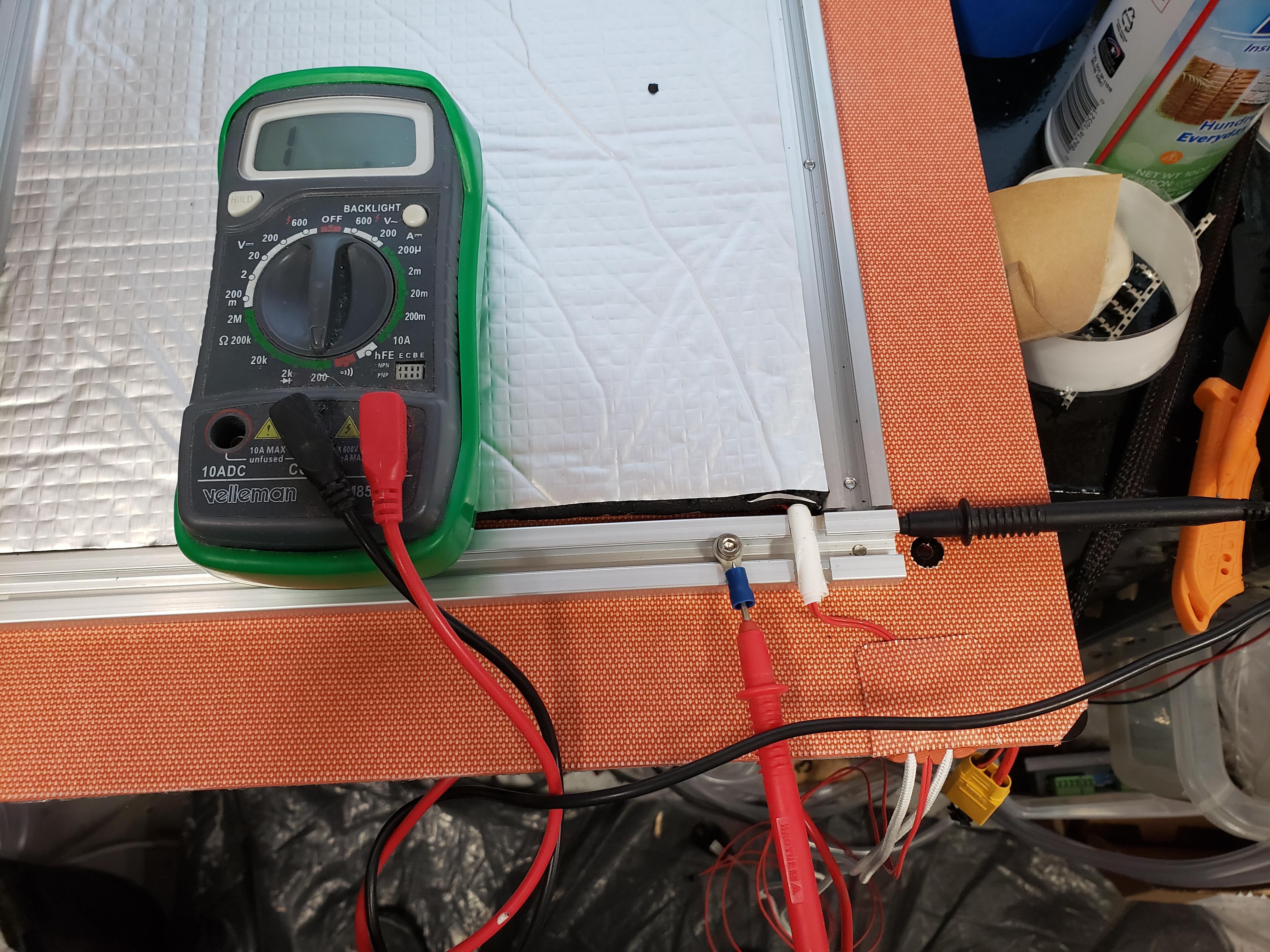
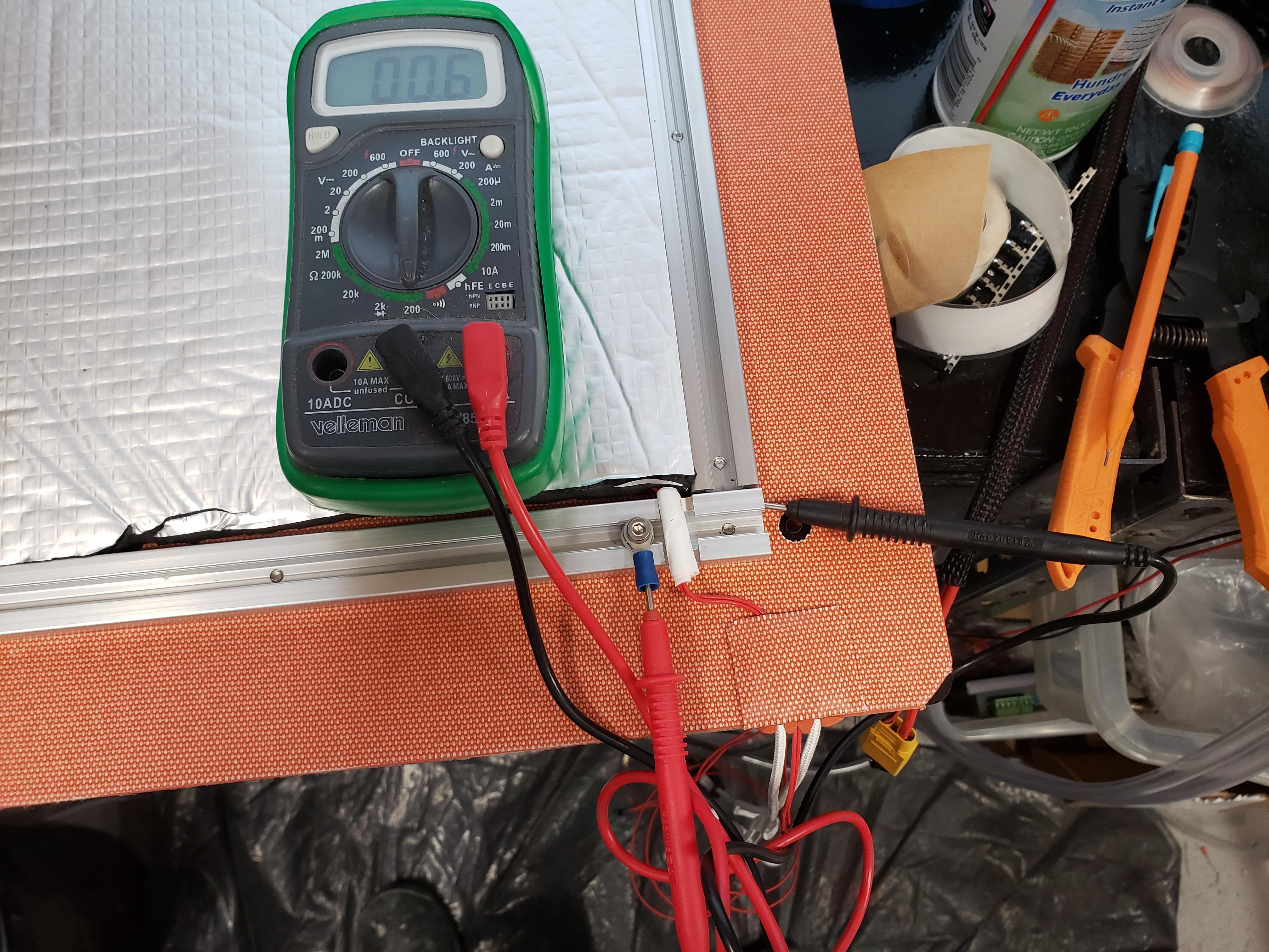
One important thing to remember is the aluminum may have a clear coat or some oxidation on it preventing a good ground without some additional measures. Here was my first ground attempt, note it is reading as an open circuit, not good.
![]()
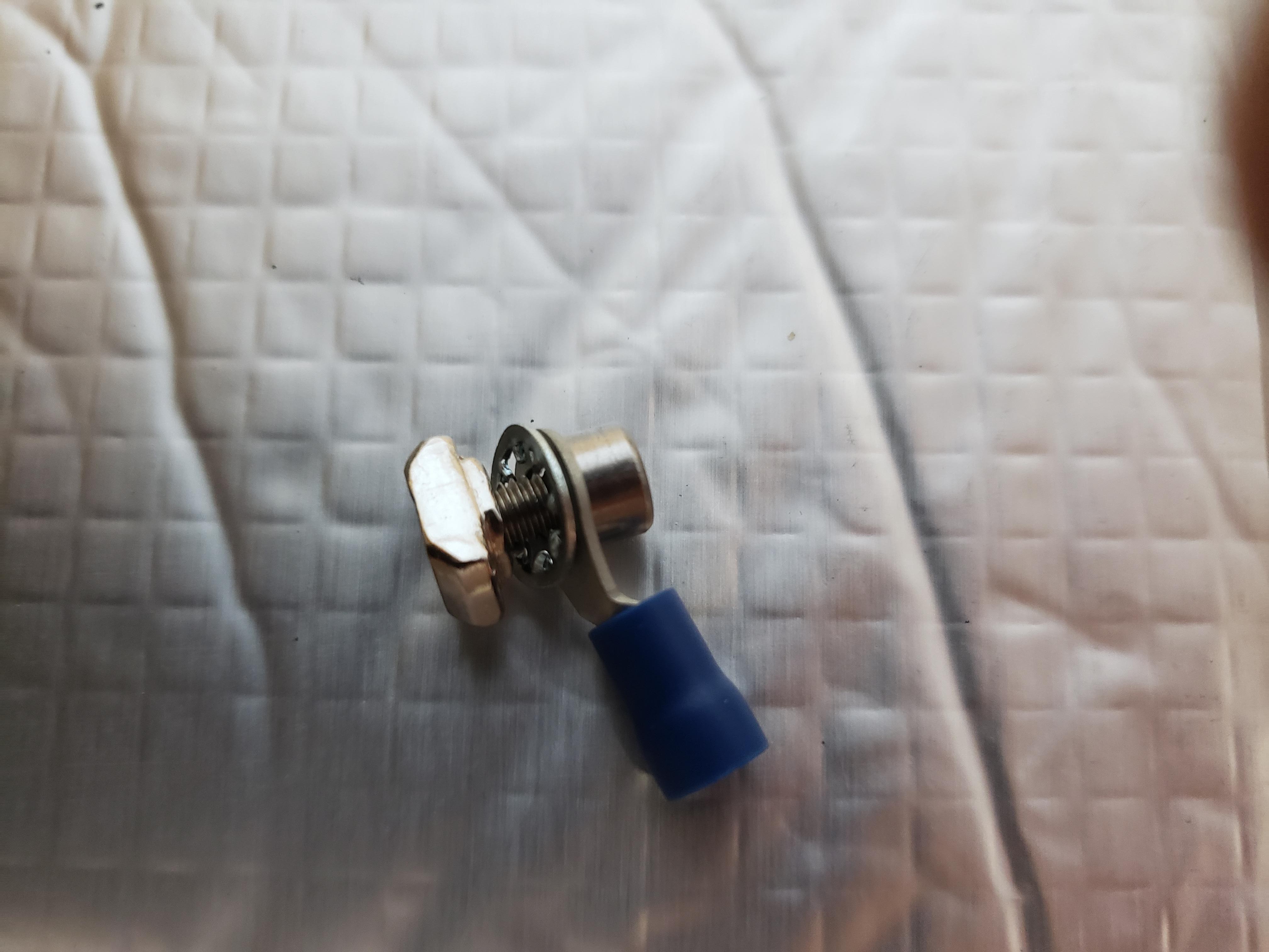
I then made 2 changes. One I added a star washer to the grounding connector so it would dig into the aluminium.
![]()
I also sanded the spot where I attached it lightly. And voila, a good ground.
![]()
For the photo I'm just checking the aluminum piece, but you really must check the edge of the aluminium bed itself. Be sure to press the tip of the probe into the bed(this is why you check the edge) to get through any clear coat or oxidation. I did this and the reading was the same.
Once the ground wire is attached I'll finish insulating the edges.
-
First steps
07/30/2020 at 18:27 • 0 commentsThe first step(no photos) was to remove the original insulation from the hotbed as well as the insulation I added.
I scraped it away with a plastic scraper to not damage the original heater in case I ever wanted to use it again. That left some adhesive residue which mostly came off after soaking it with water+dish soap and letting it sit, and scraping, and repeating. I removed the original thermistor and its kapton tape and removed a couple small remaining adhesive spots with Goo Gone adhesive remover.
Once that was done I removed the silicone with the scraper from around the power wires then desoldered those. I used a butane iron as it was able to get hotter than my normal iron. I melted some evil Lead solder into the existing solder on the board to reduce its melting point and as I was able to melt it I used a solder sucker to remove it. Eventually got the wires off and then used some desoldering braid to reduce the remaining solder. Then used the iron to make sure what was left was smooth.
Then cleaned the whole surface thoroughly with dish soap and water and then alcohol.
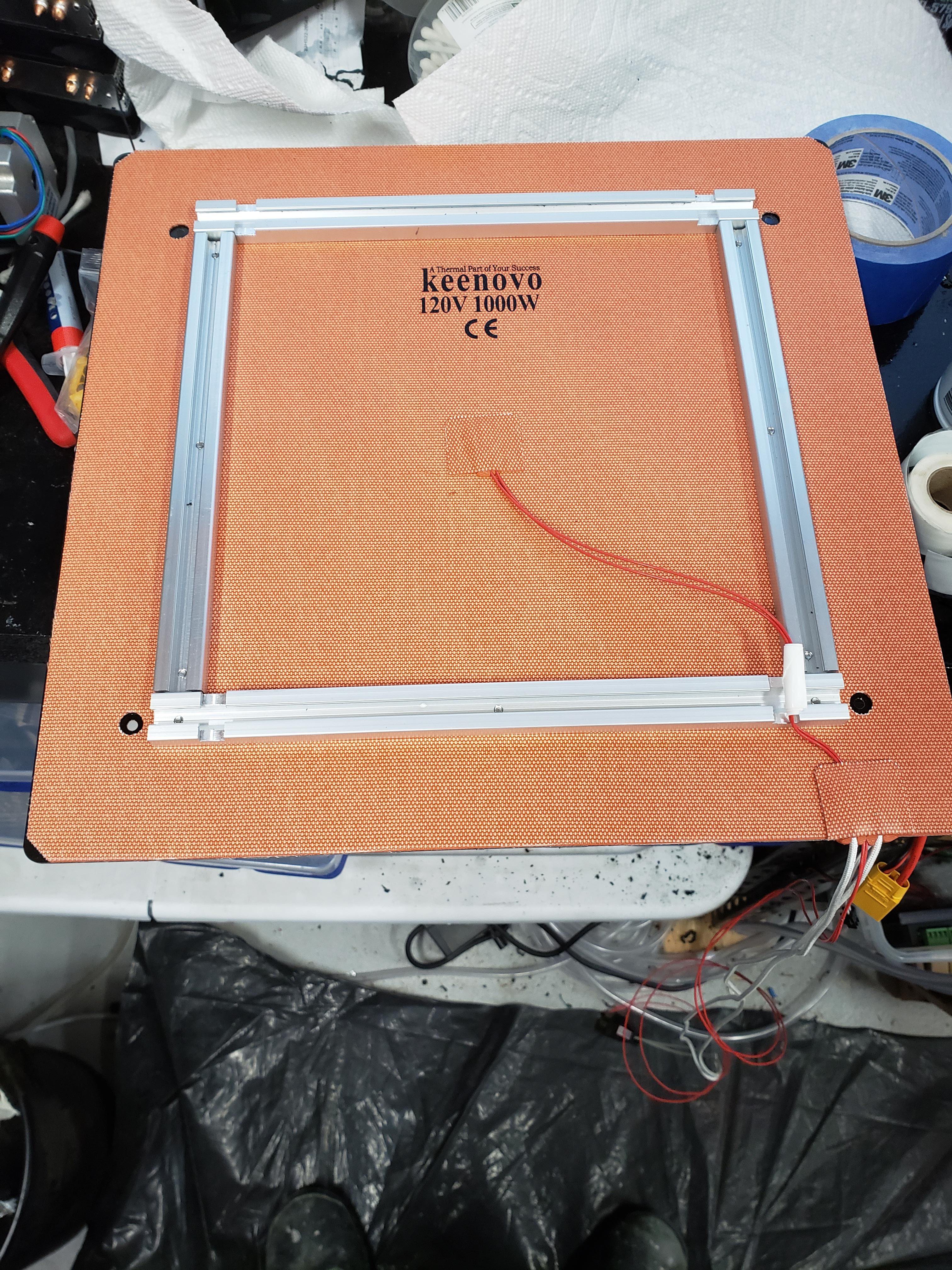
I folded back about 1" of the covering of the adhesive on the new heater and carefully lined it up with the screw holes and applied it, then while lifting the heater slowly removed the rest of the covering of the adhesive while pressing the heater onto the bed being careful to not get any bubbles.
Then I left heavy things on it over night.
Then I put the metal crossbars back on and tightened them loosely.
Then I briefly heated the bed and tightened the cross bars some more.
Then I put a connector on the thermistor and matching the existing connector and set it on the printer. I hooked up an SSR(details to follow) and recompiled the firmware on the printer for a Type 11 thermistor which looks correct. I also took this time to upgrade to a 170 max bed temp.
I then ran it up to 150C and carefully finished tightening the screws and let it cool and removed it to insulate and ground. The white bit is self fusing silicone to prevent the thermistor wires from chafing on the aluminium.
I pushed a little slack in the thermistor wires and slid the aluminium bracket under them rather than smashing them.
![]()
Ender 5 Plus Hotbed Upgrade
Upgrading the Ender 5 Plus to a 1000W AC Silicone Heater