 Shu Takahashi
-
BOM Update
10/05/2020 at 15:16 • 0 commentsAs part of our update, we upgraded our BOM for it to contain more information about our device.
Level Hierarchy
First, I included a level hierarchy. This makes it easier for the reader to understand how the different components come together. Level 1 is the main device, and as the level go higher, you can see the components that are used in each sub-assembly.
As an example, on how to uses this nomenclature, let's pick component BUPCB2B Base Unit Controller PCB. As you can see, this component is listed as LVL 4. If you go up, you'll see that the first LVL 3 sub-assembly is the BUMUV2 Base Main Unit. That means that BUPCB2B is part of BUMUV2.
Component Index
We also assigned a Tag to all of our components to help us understand them faster. Tags begin with either E, I, or X. "E" means that this component comes from an external supplier. "I" indicates that this is a component that we designed and produced. Finally, "X" is used for sub-assemblies.
Component Universality
One of the main goals of this project is to make this device accessible. To accomplish that goal, all of our external supplier components were checked to verify their accessibility in Central and North America (MEX/USA/CANADA) and Japan. This will help guarantee that people living in these zones will be able to find the necessary components produce their own MAGPIE MIDI.
-
Long Big Update
10/05/2020 at 13:54 • 0 commentsHello everyone, it’s been a while since we last updated the community on the progress we’ve made. First of all, we are incredibly honoured to be one of the finalists for the Hackaday Prize 2020. We are extremely excited to keep on pursuing this project. I know it’s been a long time, but trust us, we’ve been working hard to make more improvements so we can get this device to people that need it fast.
Admittedly, we have found it more difficult to make progress because of the time constraints. I started my first year at the university about five weeks ago in Canada (but I’m in Japan) which has taken away the time I had to work on this project during the summer holidays. Pato changed his position at his company and this made it more difficult for both of us to coordinate together, not to mention the significant time difference we have between ourselves.
Nonetheless, we have both tried to contribute as much as we could to this project. Although we’ve worked on this project throughout the last month, it’s been more difficult to write a log for each of the small chunks of the tasks we finished. But enough about ourselves, here is a long update of everything we’ve accomplished in the last month. I’ve written this log with the headings listed below, and hopefully this will make it easier to read this update.
- Hardware Updates
- New PCB designs
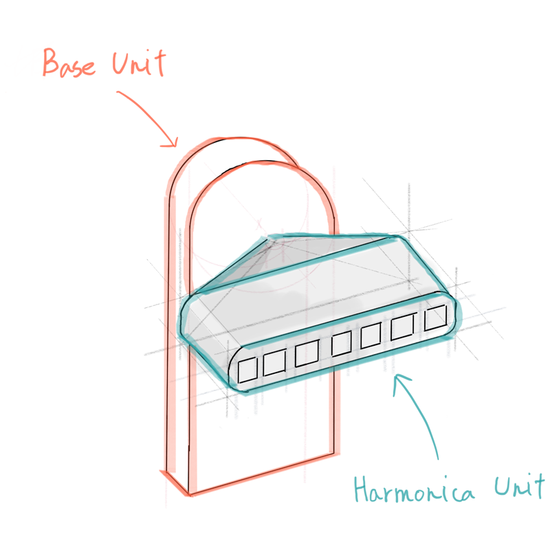
- New harmonica unit design
- Testing the new design
- Other updates
- Software Updates
- New GUI for configuring the device
- Arduino code to write configuration settings to EEPROM
- Other updates
- General Updates
- Exhibition at Maker Faire Tokyo 2020
Hardware Updates
We’ve made significant changes to the hardware of Magpie MIDI. Magpie MIDI 2.0 aims to be more fabricatable at large scales. Although the end result is in no means perfect, it was overall a good experiment to test the design ideas we had after creating the first prototype.
New PCB designs
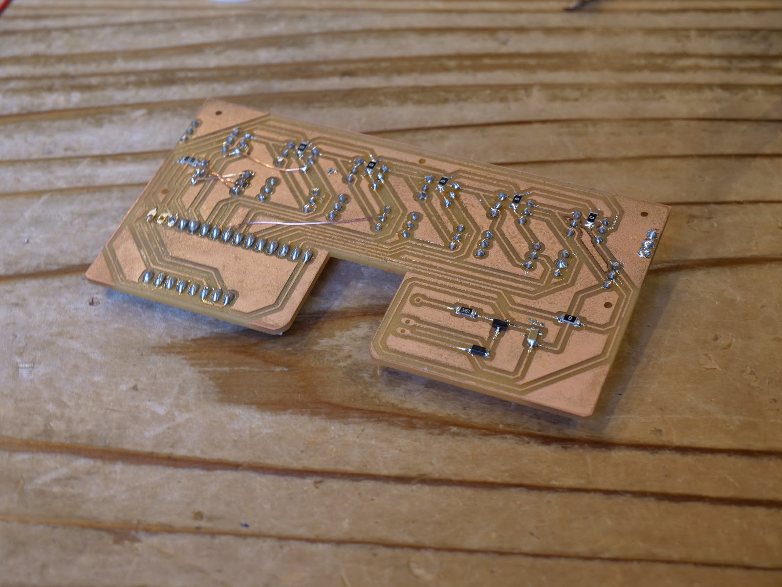
We mentioned that we were going to move on from CNC milled circuit boards to manufacturable PCBs, and this is exactly what we have done. We’ve redesigned the PCBs both for the harmonica unit and the base unit.
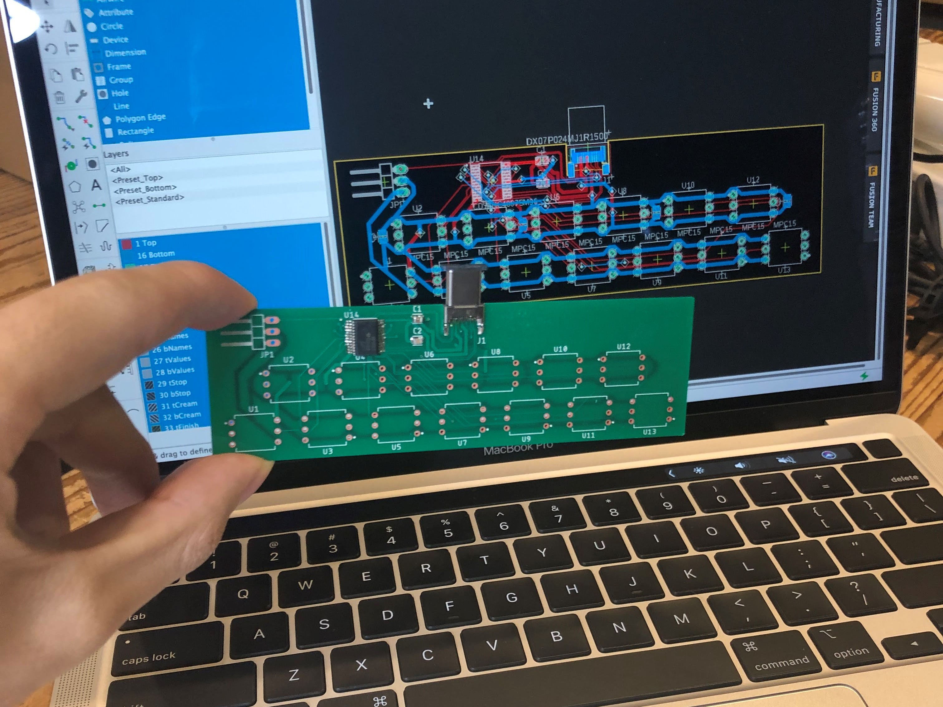
The harmonica unit’s PCB now uses the SMD version of the multiplexer, CD74HC4067 as well as other SMD components except for the air pressure sensors. This made the PCB much more compact and opened the door for new potential designs. In addition, we’ve also added a male USB type-C connector to the PCB for reasons we will explain in the following section.
![]()
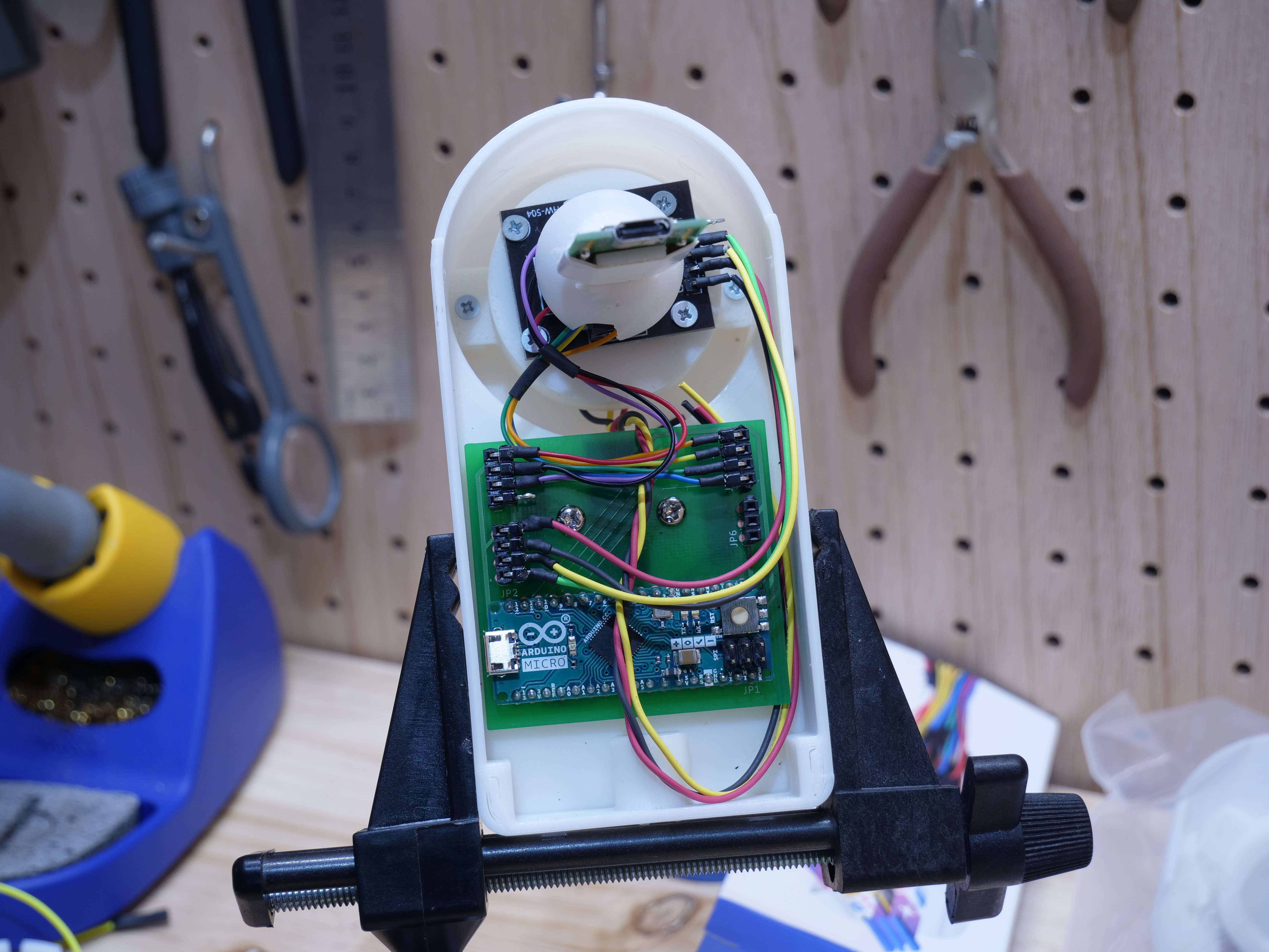
The base unit now has two PCBs. One is used to connect the USB type-C connector from the harmonica unit to the main PCB. The other is the main PCB which has the Arduino board. We’ve decided to switch from Arduino Leonardo to Arduino Micro so that the base unit is more compact, and the USB cable is able to come out from the sides, not from the bottom of the base unit. Although this has improved the base unit overall, in the future, we want to get rid of the Arduino and make our own 32u based boards to better customize it to our needs.
New harmonica unit design
Because of the redesigned PCB, we were able to make significant improvements to the harmonica unit. In the first prototype, it was extremely difficult to assemble the harmonica unit as it required multiple components to be held together at the same time. In the new harmonica unit design, we were able to simplify the design so that it’s easier to fabricate and assemble.
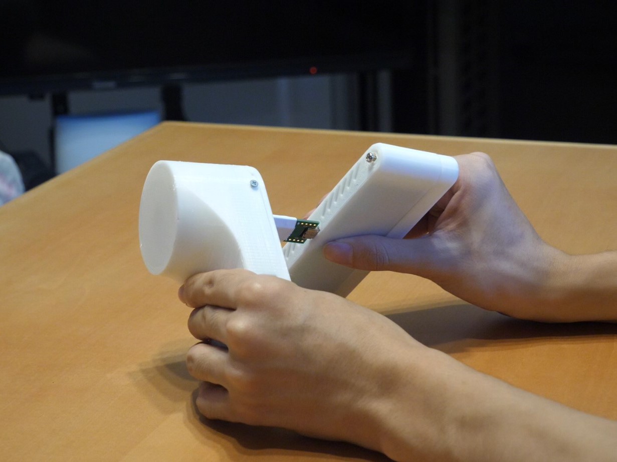
As I mentioned earlier, the harmonica unit’s PCB now has a male USB type-C connector. This connector is used to connect the electronics in the harmonica unit to the electronics in the base unit. In the first prototype, this connection was made using thin wires that ran through the joystick unit. This made the assembly much more difficult and made the base and harmonica unit inseparable. By using a USB type-C connector, the two units can now be taken apart for easier assembly and better transportability.
![]()
![]()
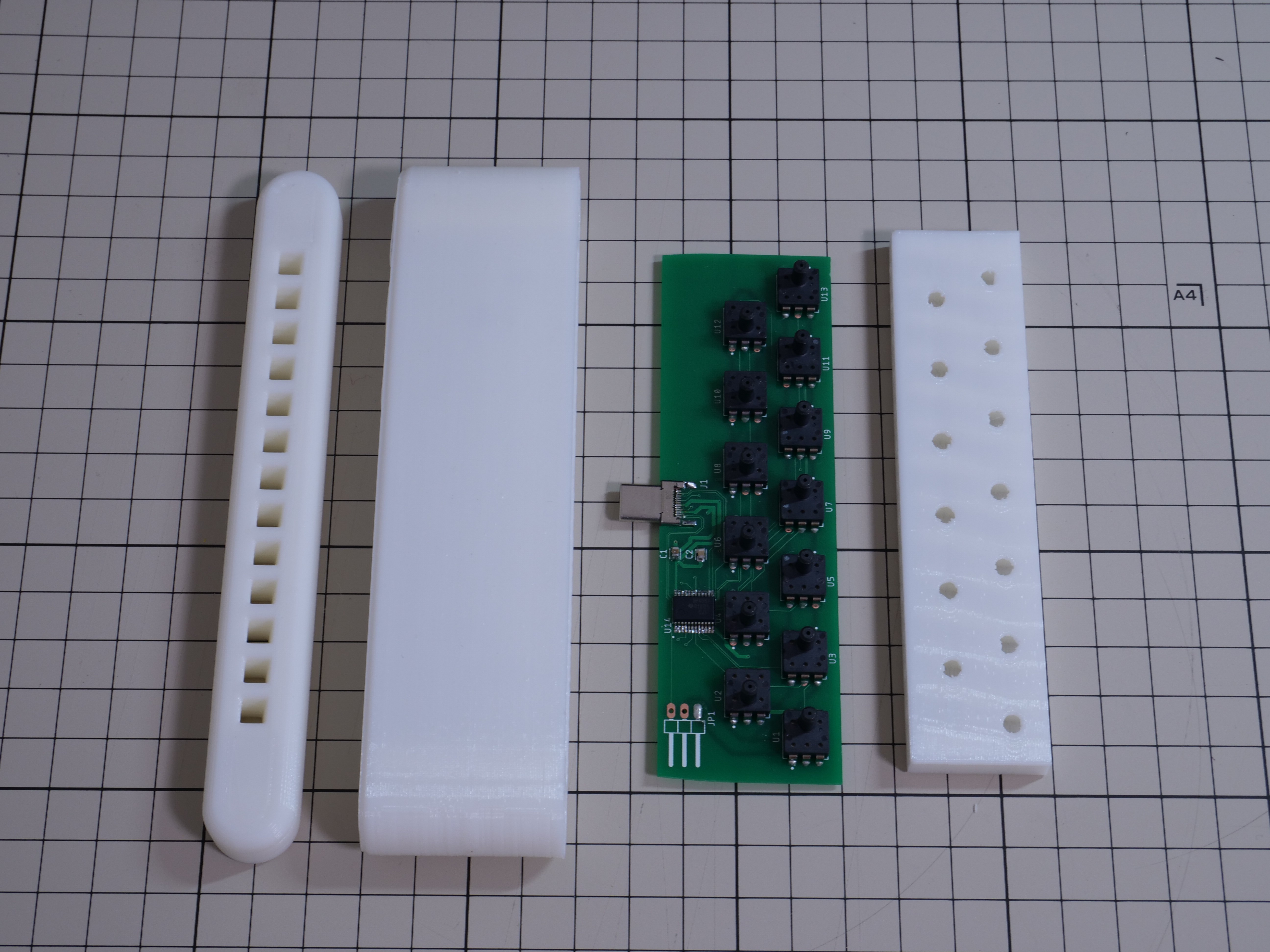
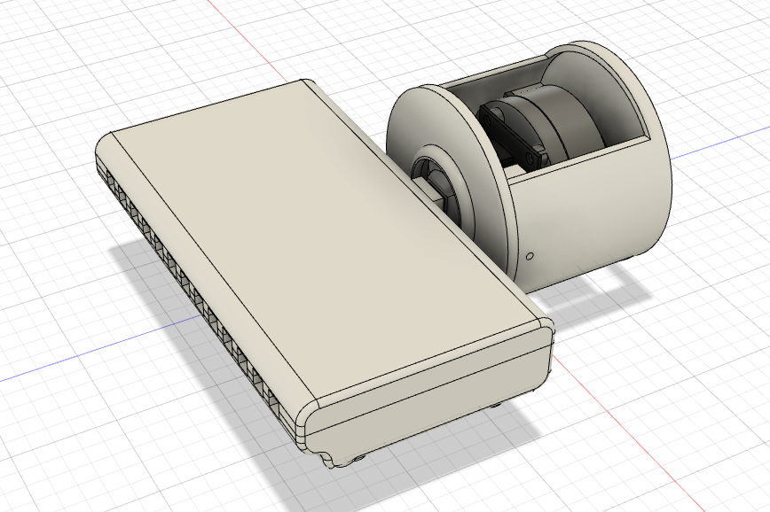
The outer casing is now in the shape of a single piece sleeve instead of the top and bottom cover design we had in the first prototype. This design again, simplifies the assembly. In addition, the sleeve design is much easier to 3D print on a FDM printer. With this design, it will make replacing breath filters in the mouth piece easier as well although we have yet to design the mouthpiece with filters.
![]()
![]()
Testing the new design
As I assembled and tested the new harmonica unit, this is when it became apparent that there were some issues with either the new PCB design or issues that arose from soldering the SMD components. Although my initial tests with the multimeter indicated that the PCB had no wiring problems, when the sensors were read by the Arduino, three of the sensors gave out a range that was beyond a typical value. For reasons still not entirely clear, the sensor values did not change when the air pressure was changed on purpose. For this reason, we were unable to use the second prototype properly.
In addition, an error was made in the circuit design for the PCB that is supposed to connect the harmonica unit to the base unit. One of the pins in the USB type-C connection was not connected to the right soldering pad on the PCB. Luckily, we were able to use a commercially sold USB type-C breakout board (which is also open source) to continue on with our testing. This is a minor error and can easily be fixed when we order the PCBs again.
I believe that the root cause of these problems come from the time constraint we had. We really wanted to get the Magpie MIDI V2.0 to work like the first prototype but with better improvements. Instead, by making haste, we must have made an error either in the PCB design or in soldering the small SMD components onto the PCB.
Nevertheless, Pato and I are confident that we can get this PCB design to work. Getting the PCB design right the first time is always challenging for any project. Because we know for a fact that our circuit design works on a breadboard and a CNC milled circuit board, we believe that this is only a matter of minor error we made in creating the electronics for the second prototype.
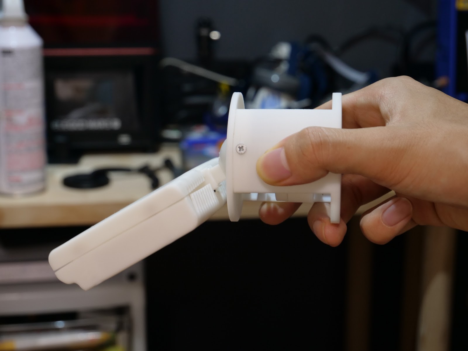
Assembling the harmonica unit and the base unit also showed that, like the first prototype, the harmonica unit was still too heavy for it to be supported by the springs in the joystick. Like with our first prototype, we used elastic bands to support the harmonica unit’s weight. This is a hardware design issue that will need to be fixed because using elastic bands to support the harmonica unit is not ideal. We have come up with two different ways to resolve this issue and we plan on implementing a fix in the next iteration of the device.
On the flip side, the ease of assembly of the harmonica unit was significantly improved. Whereas the first prototype required various tools and a considerable time to assemble, the new design was able to be assembled in less than a minute using only a screwdriver. In addition, making the harmonica unit and the base unit detachable proved to be a great idea. It not only made the device more portable, but it also made assembling the device more easy.
Other updates
Looking at the harmonica unit PCB design, you may notice that there are three extra pins that point outward. This is for a new feature idea we came up with as we got more feedback from the people at the UCPLA. These three pins are reserved for further expansion of the device. We know that cerebral palsy and other physical disabilities have various effects on body movement. With these three pins, we want to allow our users to have more options in how they control the device by adding additional “modules” via the three pins.
For example, there may be users who struggle to tilt their heads to operate the device. Tilting the head would be necessary to switch modes (i.e. to enter MIDI mode from keyboard mode) but this would not be possible for them. If another sip and puff switch (single air pressure sensor with casings) can be attached on top of the harmonica unit via the three pins, it could be used to switch the device’s modes without the head tilt movement.
These three pins could also be used to add additional functionalities. Adding an additional air pressure sensor module could be programmed to activate a specific command that the user wants constant and immediate access to. With the additional pins already available, there would be no need for custom modification of the device by our users. The three pins are GND, VCC and Analog/Digital pins. Therefore ideas for additional modules to be added to Magpie MIDI is endless.
Software updates
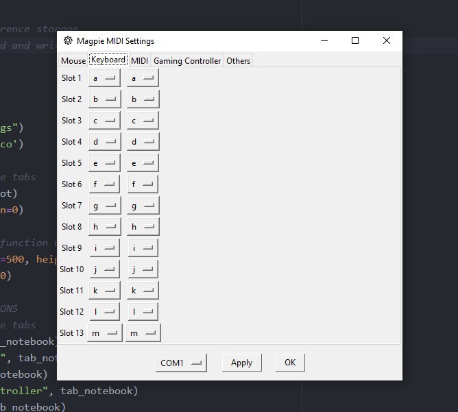
New GUI for configuring the device
As we mentioned previously, we want our device to be fully customizable without the need to use computer programming language. We have written a PC/Mac software that will allow users to customize what each of the air pressure sensors do.
For example, if a user wants to change the musical scale from the device’s MIDI output, they will be able to select the appropriate notes from a dropdown menu and configure the new settings to the device all without touching a single line of code.
![]()
Unfortunately, we ran out of time (before posting this update for the final round) to implement the pyserial library into our code. This is part of the code that was supposed to send serial AT like commands to the Arduino in the backend of the software. We ran into issues with getting the library to work together with multiple python files we were already working with. However, with more time, we will be able to get this running.
The GUI of the software is finished and the codes for these are available on our Github repository page. We realize that this software is not the most intuitive and most user friendly software. We have many ideas for how we can make the software more intuitive, but we wanted to get the basics done first. As of now, the GUI software is written in python using Tkinter; however, after we prove that the configuration system works, we plan on using other GUI libraries (we were thinking Electron.js combined with other web development tools) to improve the GUI of the configuration software.
Arduino code to write configuration settings to EEPROM
The configuration system will also require additional code in the Arduino side as well. We have designed the configuration system to store the user’s configuration settings into the EEPROM of the Arduino. The system is similar to an AT command system or a Unix terminal system. Specific reserved ascii letters are used to either program or pass on information between the Arduino and the configuration software on the PC/Mac. Each aire pressure sensor has its own memory address in the EEPROM to store the value. We have successfully gotten this EEPROM writing system to work, and although useless without the software, the code can be found in our Github repository.
Other updates
Pato and I along with our friends who have been very interested in this project have come up with an idea to gamify the process of learning to use this device. We realise that the device will at first have some learning curve. Afterall, learning to play the harmonica requires practice and frequent usage. Therefore, our idea is to create a gaming application (that goes along with the configuration software) that will teach the users how to use this device and allow them to practice using the device in fun and interactive ways. We have not started working on this idea yet, but we will definitely be working on it soon.
General Updates
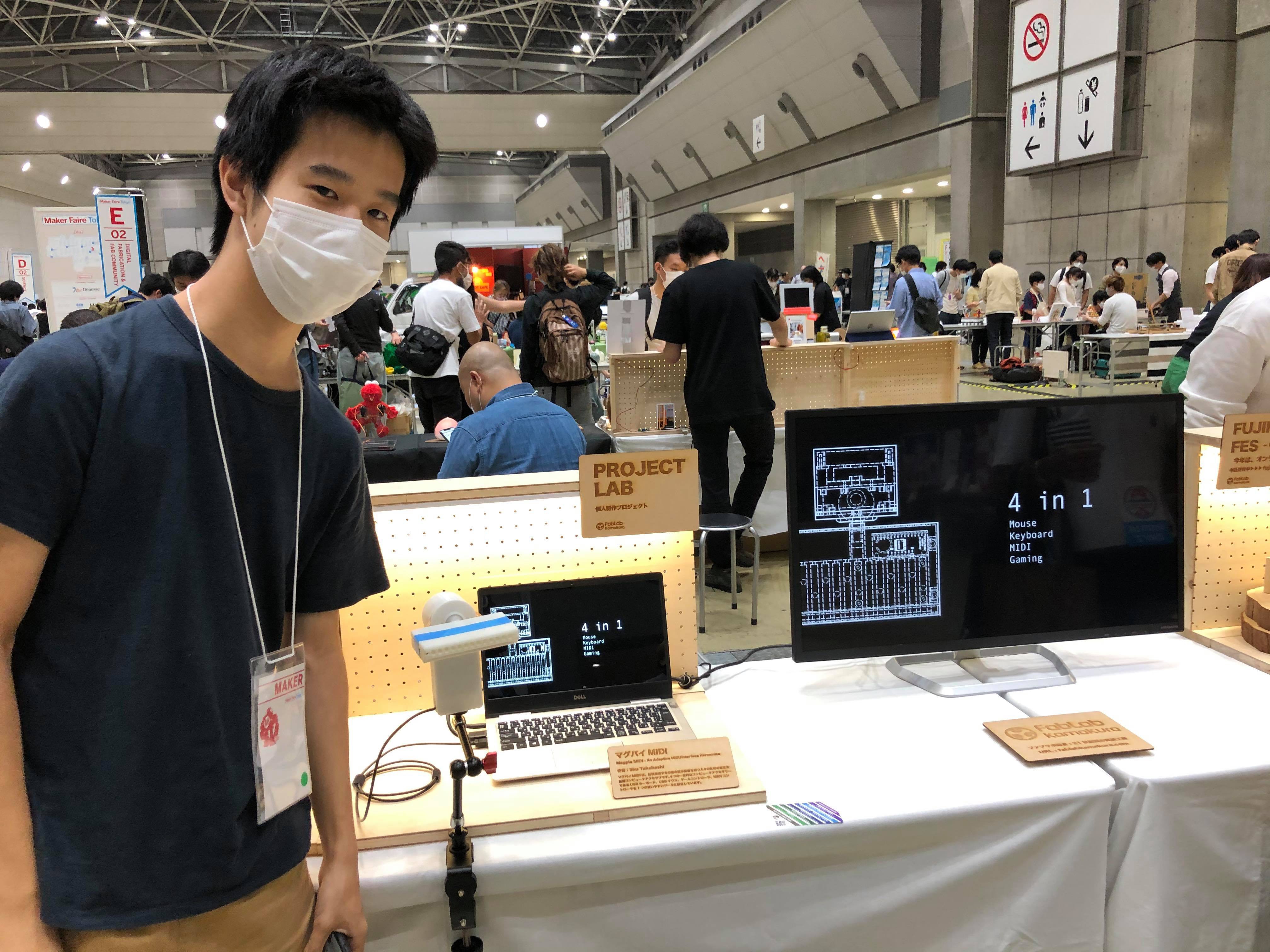
Exhibition at Maker Faire Tokyo 2020
We showcased our first prototype along with the first video at the Maker Faire Tokyo. We heard many positive feedbacks and comments. One of the people that visited the booth excitedly mentioned that one of his friends, who has a physical disability would find our device extremely useful and was interested in following up with our project. Similarly, I also had a friend who knew somebody that would love to use the Magpie MIDI when I made a post about this on Facebook.
We also met a director of a Japanese company who specialise in creating robotics and social solutions for people with disabilities. He was also interested in this project and wanted to hear more from us.
![]()
The numerous feedbacks we’ve received online has also made us realise how our device is creating excitement and hope for some. Although creating this device is a small step towards a specific problem, we feel incredibly responsible to get Magpie MIDI to people who would find it useful.
-
Hardware Update - Prototyping the Harmonica Unit
09/01/2020 at 12:50 • 0 commentsWe have been working to prototype the harmonica unit for the past couple of weeks, but we have yet to share this on our log page. However, now that most of the work on the harmonica unit is done, we’re ready to share what we have accomplished so far.
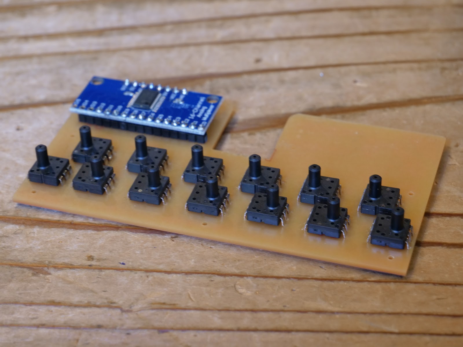
At this stage, the design requirements for the harmonica were very clear. It needed to hold an array of 13 air pressure sensors, hold the multiplexer breakout board, be in the form of a harmonica, and fit together with the base unit. This meant designing both the plastic components as well as a PCB board to hold all the electronics components together.
I first designed the air holes and the PCB to go with it. I used the same dimensions we used when Pato and I experimented with the air pressure sensor a few days ago. Designing the PCB and the air pathway component to fit together was really challenging because it required a close coordination between my CAD program, Fusion 360 and my EDA program EAGLE. I initially tried to do everything in Fusion 360 with the new update that integrated EAGLE; however, I had problems with routing and exporting at a later stage, so I used two separate programs.
Printing the air pathway component was straight forward. Although the back part of the component warped a little bit because I used ABS plastic. Fabricating the circuit board was a little bit more challenging. To begin with, this was my first time milling my own PCB using a CNC machine. Learning the process for operating the CNC machine was quite a bit of a learning curve. Also, I unintentionally designed the PCB from the bottom side. This resulted in a PCB layout that was mirrored horizontally. Luckily this problem was resolved by flipping the export image horizontally, but the whole process took about three days, which delayed this project by a few days.
In the circuit board, I also included a transistor switching circuit to control the vibrational motor from the Arduino. The first circuit board had errors, but the second attempt was a success. I was able to place all the required electronic components in the harmonica unit into a one nice PCB.
The circuit board and the air pathway plastic component fit together well on the first try which was a bit of a satisfying moment. In the air pathway component, I made a small tunnel to route the wires through so that it can access the Arduino Leonardo in the base unit.
Now all there was to design for the harmonica unit was a nice enclosure to hide all the electronic components and the air pathway component. Designing the enclosure required a bit of thinking and quite a lot of time as well. First, I wasn’t sure how the enclosure should fit together. I initially thought of making the enclosure like a sleeve, but this was not possible because we were still at a prototyping stage and so the electronics needed to be easily accessible in case something went wrong. At the end, I designed a two part enclosure that covered the components from the top and the bottom. I designed the two enclosure components to be held together using a nut and a bolt. I put an effort into hiding the screws from the top side to make the enclosure look nice.
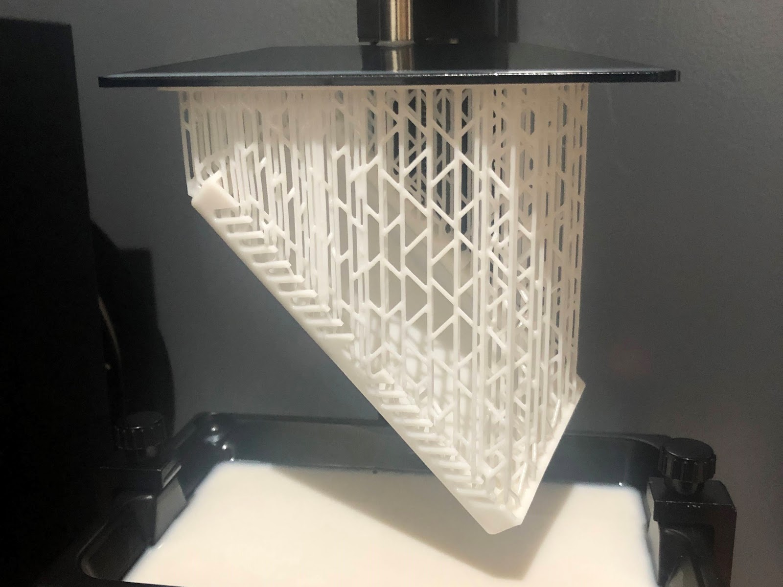
Printing the bottom and the top enclosure took a very very long time. This is partly because I chose to use an SLA printer as the two enclosure components had some complicated geometries that could be damaged from typical FDM supports. But the wait was worth it. Although there were some warps in the final print, it still looked very similar to what I designed in CAD.
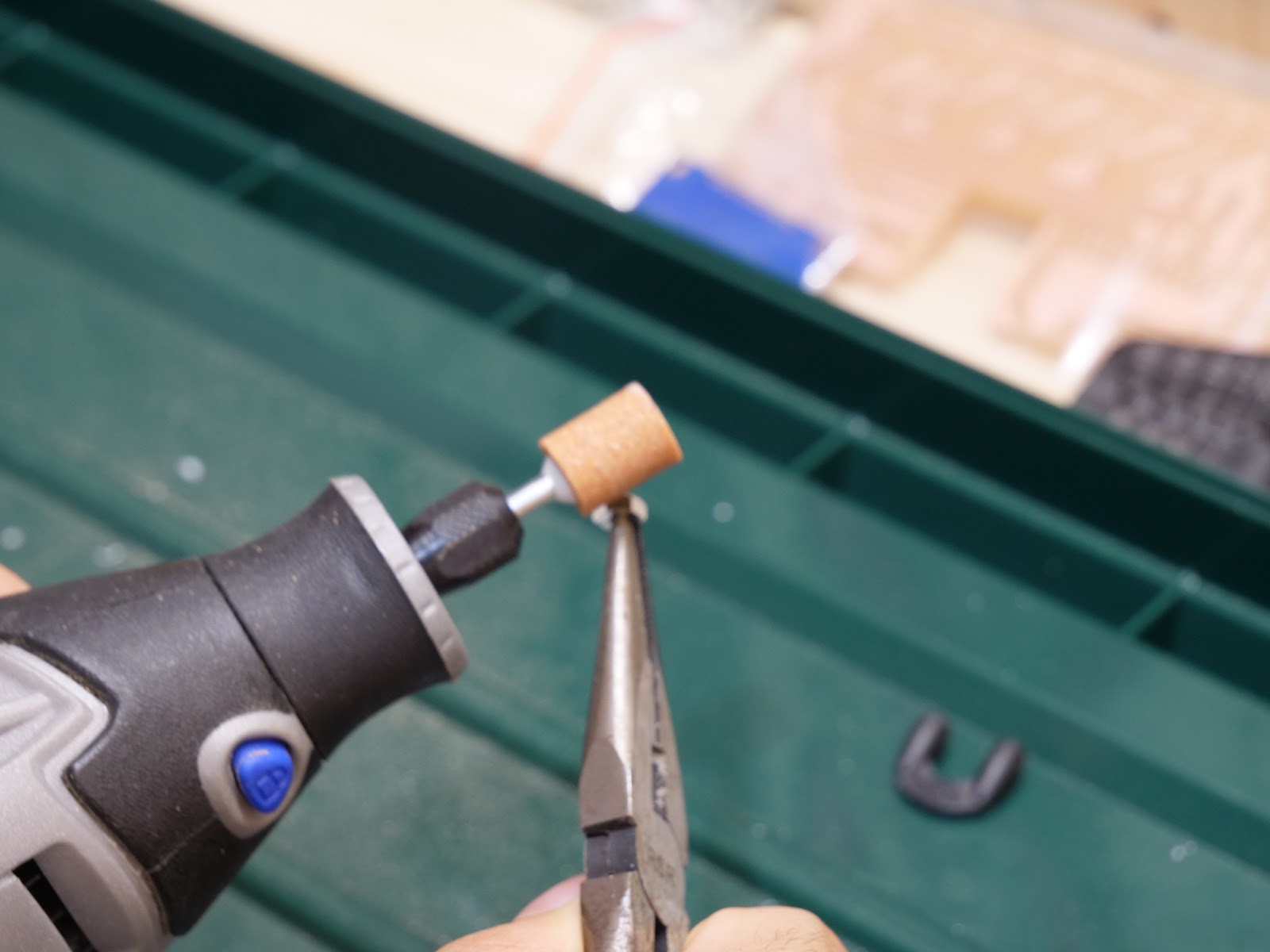
Although the prints looked great, it still needed some post processing. I filed the sides that had the supports to get a smoother surface. The pockets I designed in the top enclosure to fit the nuts came out too small. Instead of trying to reach in and remove the excess material inside the pockets, I grinded the nuts so that it can fit inside.
Everything was coming together nicely. But that was until I tried assembling the harmonica unit and the base unit together. It turned out that the harmonica unit was too heavy to be supported only by the springs inside the joystick unit.
With the deadline I set for myself approaching, my mind panicked and I wasn’t sure what to do. Fortunately, when I went to my loca makerspace, Fablab on the next day, one of the members came up with a simple yet brilliant solution to use a rubber band to add extra support. Although I don’t have a picture of this, it worked like a charm. For now, for the first prototype I will be using this solution. In the future prototype, I’m thinking of either making the harmonica unit lighter or designing a mechanical system to support the weight of the harmonica unit.
-
More Experiments with Electronics and Sensors
09/01/2020 at 11:55 • 0 commentsChoosing Electronic Components
Having chosen the air pressure sensor, there were still many electronic components to select and test. Most notably, the microcontroller and the joystick sensor.
For the microcontroller, I initially wanted to choose something with plenty of memory space and options for wireless connectivity such as the ESP32. However, as I was testing out the mouse library with my Arduino UNO, I realized that most boards I’ve used in my past projects do not support it. I found out that to use the native mouse and keyboard library, the microcontroller had to be 32u based. This narrowed down my options significantly. With the limited time I had left to order and wait for parts to arrive, my best option was to use the Arduino Leonardo. This board doesn’t have any wireless options built-in nor much memory space compared to boards like the ESP32, but it’s suffice for the first proof of concept prototype.
Arduino Leonardo has 12 analog input pins. However, for this project I will need a total of 16 analog pins. 13 from the pressure sensors, two from the joystick unit and one from the potentiometer. The first intuitive solution I had in my head was to use a multiplexer. Without much thinking, I ordered a breakout board for a multiplexer IC CD74HC4067 from Texas Instruments. When the breakout board arrived and I thought about how the program would work, I realized that I would not be able to program an external interrupt. There may be a work around to address this oversight such as using a scheduled interrupt, but for now, my option will be limited to polling. This may limit the features and performance of the output programs (i.e. MIDI or USB Mouse), but it will be enough for the first proof of concept prototype.
Choosing the joystick sensor was relatively straightforward. As Pato and I discussed in our CTQ, we wanted to make this device as accessible and affordable as possible. For this reason, we decided to use the joystick unit from a Xbox 360 controller. These joystick units can be bought in many countries around the world as a replacement part. Just for making the prototyping process easier, I also bought a joystick unit that came with a breakout board from a company called HiLetgo. This joystick unit also seemed to be very popular as I could find the identical product on Amazon in the US, Mexico and Japan. Coincidently, when I compared these two modules, the joystick was identical. So for now, I decided to use the Joystick module from HiLetgo because it already had a breakout board attached. In the later prototyping stages, I will be able to design a PCB for the Xbox joystick, so that it can also be used to build the device.
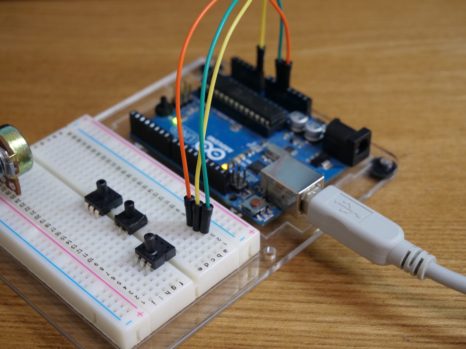
Testing the Joystick Mouse
To make sure that the joystick module and the Arduino Leonardo I ordered worked together, I ran the example code from the official Arduino documentation. The program worked as expected and I was able to control my computer mouse using the joystick module. It’s not too clear yet how this program will work in conjunction with everything else the processor needs to process, but hopefully I will figure it out in the coming days.
Testing the Multiplexer
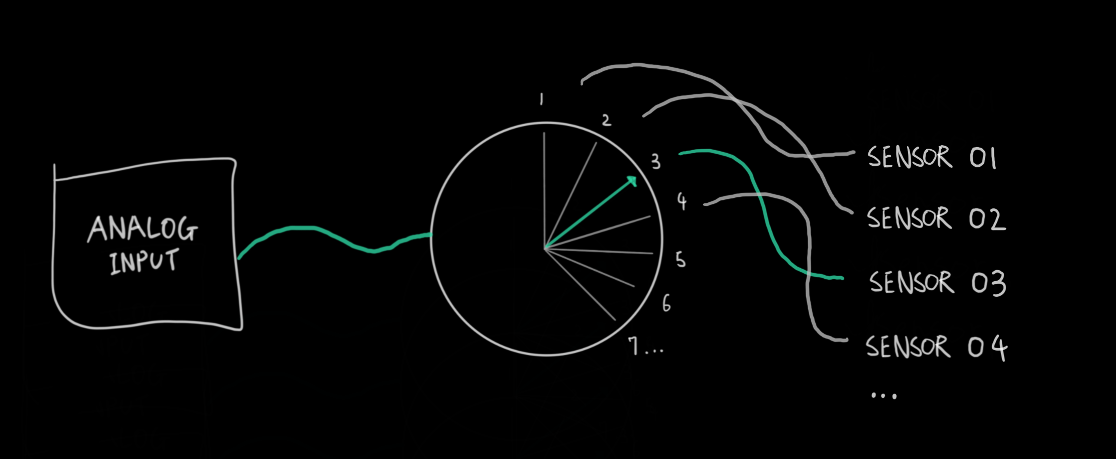
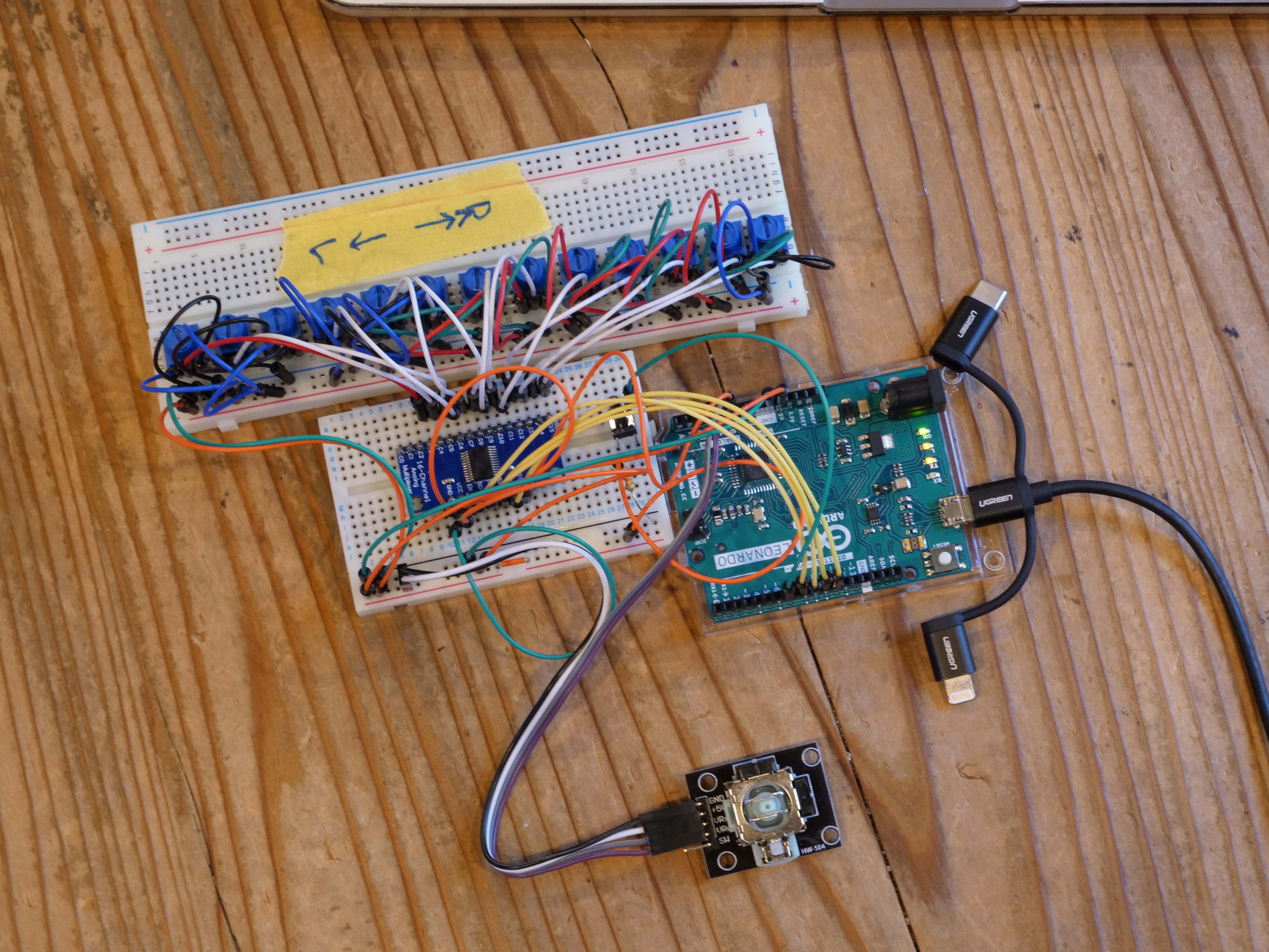
The multiplexer board will be connected to the 13 air pressure sensors. It will essentially act as a rotary switch to choose which channel to connect the Arduino to. The Arduino with the multiplexer will be constantly switching between the 13 channels and writing the results to an array.
![]()
This array can then be used by the program to take specific actions based on the sensor values. At this stage, my goal was to make sure that the multiplexer could be used to switch between the 13 channels and have the data recorded on to an integer array.
![]()
Which channel to connect to is controlled using four digital pins that receive the channel number in binary. For example writing LOW, LOW, LOW, HIGH to the four pins will connect the Arduino’s analog pin to channel number one on the multiplexer. For each air pressure sensor, the Arduino will output the channel number in binary, take an analog reading from the sensor via the multiplexer, and record this reading on to an integer array. The code below executes exactly that.
In the function readMux, the Arduino uses digital pins 8, 9, 10 and 11 to select the channel on the multiplexer. It then takes an analog reading from analog pin 0 and returns this value. In the main loop program, the Arduino then iterates through the 13 channels and writes the results to an int array named pressure_sensor.
//Mux control pins int s0 = 8; int s1 = 9; int s2 = 10; int s3 = 11; //Mux in signal pin int SIG_pin = 0; //sensor value table int pressure_sensor[13]; void setup() { // put your setup code here, to run once: pinMode(s0, OUTPUT); pinMode(s1, OUTPUT); pinMode(s2, OUTPUT); pinMode(s3, OUTPUT); //initialize control pins digitalWrite(s0, LOW); digitalWrite(s1, LOW); digitalWrite(s2, LOW); digitalWrite(s3, LOW); Serial.begin(9600); } void loop() { // put your main code here, to run repeatedly: //read through channels 0 to 12 for(int i = 0; i < 13; i++){ int sensor_value = readMux(i); Serial.print("Channel: "); Serial.print(i); Serial.print(" Value: "); Serial.print(sensor_value); Serial.print("\n"); pressure_sensor[i] = sensor_value; delay(1); } for(int i = 0; i < 13; i++){ Serial.print(pressure_sensor[i]); Serial.print("\n"); } delay(5000); } int readMux(int channel){ int controlPin[] = {s0, s1, s2, s3}; int muxChannel[13][4]{ {1,1,0,0}, //channel 3 {0,0,1,0}, //channel 4 {1,0,1,0}, //channel 5 {0,1,1,0}, //channel 6 {1,1,1,0}, //channel 7 {0,0,0,1}, //channel 8 {1,0,0,1}, //channel 9 {0,1,0,1}, //channel 10 {1,1,0,1}, //channel 11 {0,0,1,1}, //channel 12 {1,0,1,1}, //channel 13 {0,1,1,1}, //channel 14 {1,1,1,1} //channel 15 }; //loop through the 4 signal pins for(int i = 0; i < 4; i++){ digitalWrite(controlPin[i], muxChannel[channel][i]); } //read the value at the signal pin int val = analogRead(SIG_pin); //return the reading value return val; } -
Choosing and Testing Air Pressure Sensor
08/25/2020 at 02:51 • 0 commentsThe most fundamental component in our device is the air pressure sensors. All of the functionalities and actions revolve around the effective use of this technology, meaning that we need to choose a suitable sensor to have a good overall performance.
While in team discussions, we went over what were the most important aspects that these sensors should have. Like all of our other desired parts, they should be accessible and affordable.
Regarding the technical specs, we started by brainstorming the general design, like Shu described in the previous post. We knew that each one of the harmonica’s air holes would have one individual sensor. This meant that the sensors will be exposed to atmospheric pressure constantly, in contrast with manometric sensors. That narrowed our options to using absolute pressure sensors that measure gauge pressure.
As seen on our BOM log post, we considered numerous options. Shu ordered a couple of them each and we designed a test sequence to determine which sensor is the most appropriate.
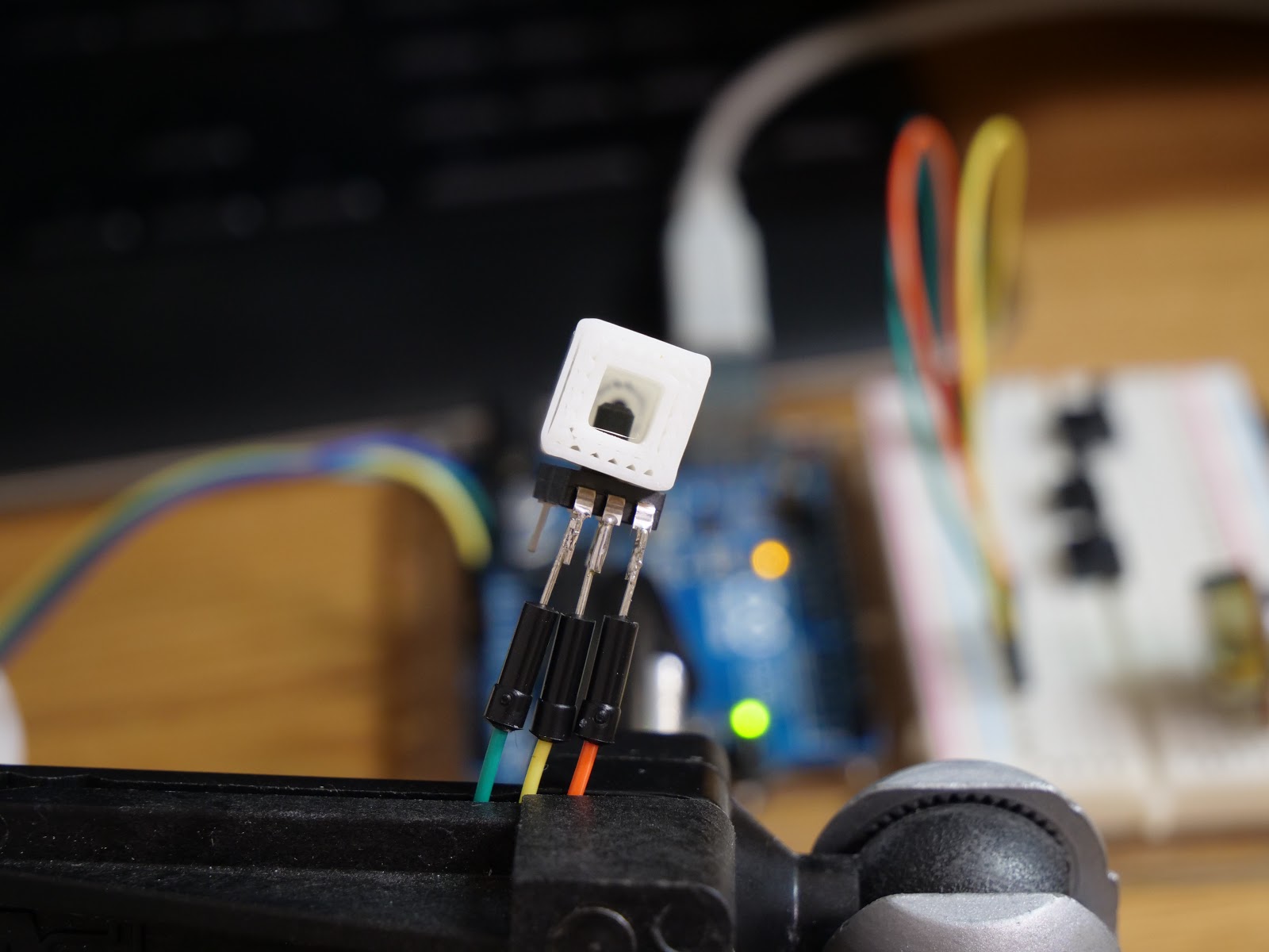
Shu designed a simple air hole to measure different interactions with the sensors. As you can see in the picture below, we chose a square air hole to replicate that of an original harmonica and added a pressure relief exhaust orifice at the back of the air hole. The dimensions of these simulations were also evaluated using fluid dynamics principles (Bernoulli’s Principle).
We considered the following formula for our design:
![]()
Where:
Δp = difference in pressure (desired on the inside vs avg atmospheric pressure on the outside)
ρ = Air density
Q = Hydraulic Head
A2= Area of the orifice
A1= Area of the air hole inlet
For these designs, we also researched the common lung capabilities of the average human. We decided to choose values that would be an average of general human capabilities, (eg. 6 m/s blow airspeed[1] / 0.8 psi exhalation pressure). With the blow speed and the cross-sectional area of the airhole, we calculated the head value and proceeded to iterate until we decided to set for a 2mm diameter orifice.
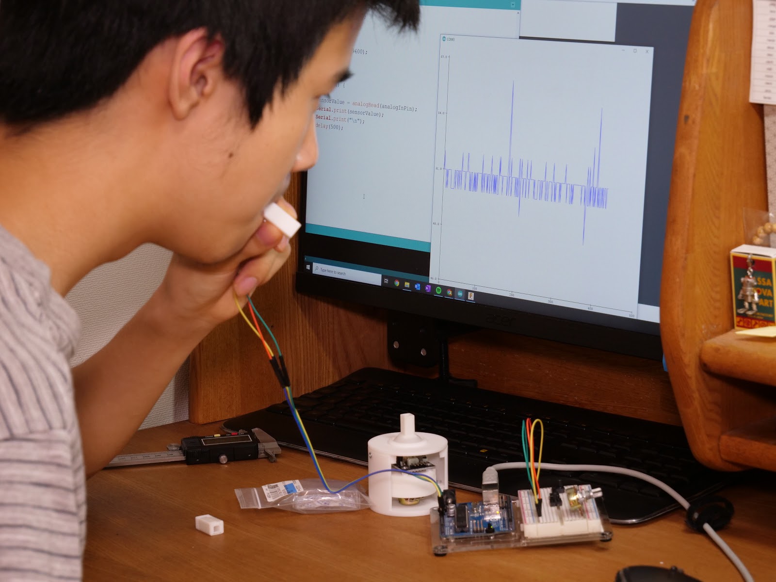
As you can see in the picture below, my partner Shu conducted the tests for each of the sensors and its compatibility with our designs.
An important thing to note is that we are considering a blow and draw functionality in our device, just like in a regular harmonica. That is why we had to make sure that our potential sensor could detect both sip and puff.
After the tests, we concluded that the MPS-2400 series sensors were the most suitable. We are confident we’ve made the right decision choosing this sensor, especially because of the process we used to select it. It will definitely bring the best out of this new adaptive tool.
References:
[1]Flow Through an Orifice
https://mcnallyinstitute.com/13-html/13-12.htm[2]Human Exhaled Air Energy Harvesting with Specific Reference to PVDF Filmhttps://www.sciencedirect.com/science/article/pii/S2215098616300830
[3]Maximum Static Inspiratory and Expiratory Pressures with Different Lung Volumes https://www.ncbi.nlm.nih.gov/pmc/articles/PMC1501025/ -
Hardware Update - Prototyping the Base Unit
08/21/2020 at 01:43 • 0 commentsThe first part we decided to start designing was the base unit. This part is responsible for providing the joystick movements as well as the MIDI knob (potentiometer) movements.
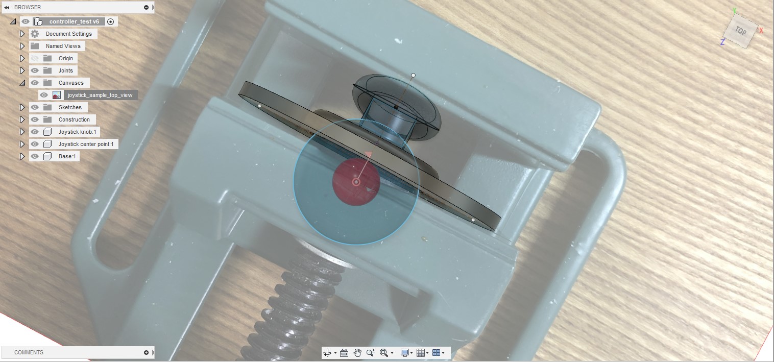
We decided to work on this first because we were still discussing how the harmonica unit would work. Besides, working on this part was one of our top priorities as this must function flawlessly and hold the harmonica unit steadily. I had an idea of how the joystick module and the potentiometer were going to function together, so I made a quick sketch before creating any models in CAD.
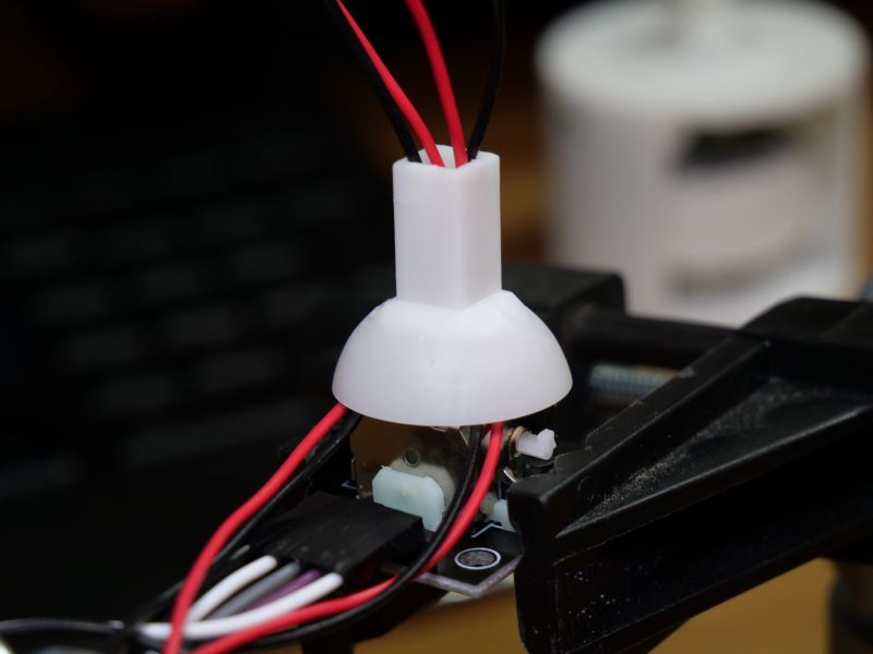
I began by creating simple test designs for the joystick handle part using Fusion 360. I had never 3D printed parts for a joystick before, so I wanted to make sure that I could design this component properly first. I took a picture of the joystick handle that came with the module and made measurements from there. I also added a ball joint and a cover to ensure that the joystick could still move freely.
Before moving on to designing the base unit, I also decided to test fit the joystick module and the joystick knob handle to find the appropriate measurements. It’s always difficult to find the right dimensions for the parts to fit together snuggly and this time was no different. Luckily for this test component, only two re-prints were needed.
Now that I had tested some of the detailed parts I was concerned with, I was confident that I could design the entire base unit. The first draft of the design took about two hours. For now, I decided to use small wood screws to hold the components together. I plan on considering using other methods for the assembly process later.
All of the components printed without any major issues, except one. The component I had trouble with was the joystick handle. This component was both difficult to design and fabricate. This component had to be designed so that wires from the circuit board inside the harmonica unit could pass through the component while providing the snug fit to the joystick module. In terms of fabrication, I first tried 3D printing the component with an FDM printer, but as you can see in the photo, the outer part was too thin. So, I tried printing this component with an SLA printer. It worked but I had to re-print three times and make additional adjustments. As you can also see, in the final version, wires could pass through without affecting the snug fit to the joystick module.
I also came across another issue. The rotary joint between the joystick module and the potentiometer wiggled significantly when the joystick was moved. I should have noticed this in CAD, but it’s always a challenge to think about how things are going to work in the real world versus what it looks like in CAD.
To make the platform, which the potentiometer module sits on more stable, I added a circular guide around the potentiometer to provide additional support.
It took a while to make adjustments, wait for the 3D printers, and to test fit the components; however, all this patience paid off at the end and I was satisfied with the result. The video below is a short demo of the base unit.
All there is left to do for the base unit is to add the enclosure for holding the electronics components that will be located in the base unit. The walls of the base unit still wiggles a little bit, but I hope to resolve this issue in the next prototyping stage.
-
Bill Of Materials
08/21/2020 at 01:25 • 0 commentsTo move forward, we decided to organize our proposed components in an excel sheet. The purpose is to evaluate and compare each one of the parts against its alternatives to meet the specified ends. We created a document dubbed “Bill of Materials Draft” where we listed components based on our desired functionality. We included different alternative components for each functionality. For each part, we gathered information like a link to its datasheet, a list of suppliers with different prices, its picture, and a brief description.
Before we had this, discussion on specific sensors was not efficient. This document has definitely helped a lot in deciding the main components. As of now, we have most of the major components on our BOM, and we expect to add more components as we make more progress.
-
CTQs and Defining Our Project
08/21/2020 at 01:10 • 0 commentsWhile discussing the scope of the project, we had different ideas about the functionalities the device would have. We had been considering multiple features until that point, but nothing was really set in stone.
That is why we decided to evaluate the potential the device could have. Through research and discussion, we attempted to define its capabilities.
We settled on the following functionalities:
- MIDI Instrument: A mouthpiece simulating a harmonica will be built to control a Musical Instrument Digital Interface (MIDI). The device will have 13 airways with built-in air sensors, each of which can be configured to execute different commands. As a musical instrument, it would be able to play numerous octaves and notes through the interface.
- Gaming Controller / Mouse: The device will also work like a computer mouse and a gaming controller. It will support numerous additional outputs including left and right-click to game function buttons that are on typical gaming pads.
- Keyboard: The13 air sensors will also have a “key” functionality allowing users to “type” using the harmonica.
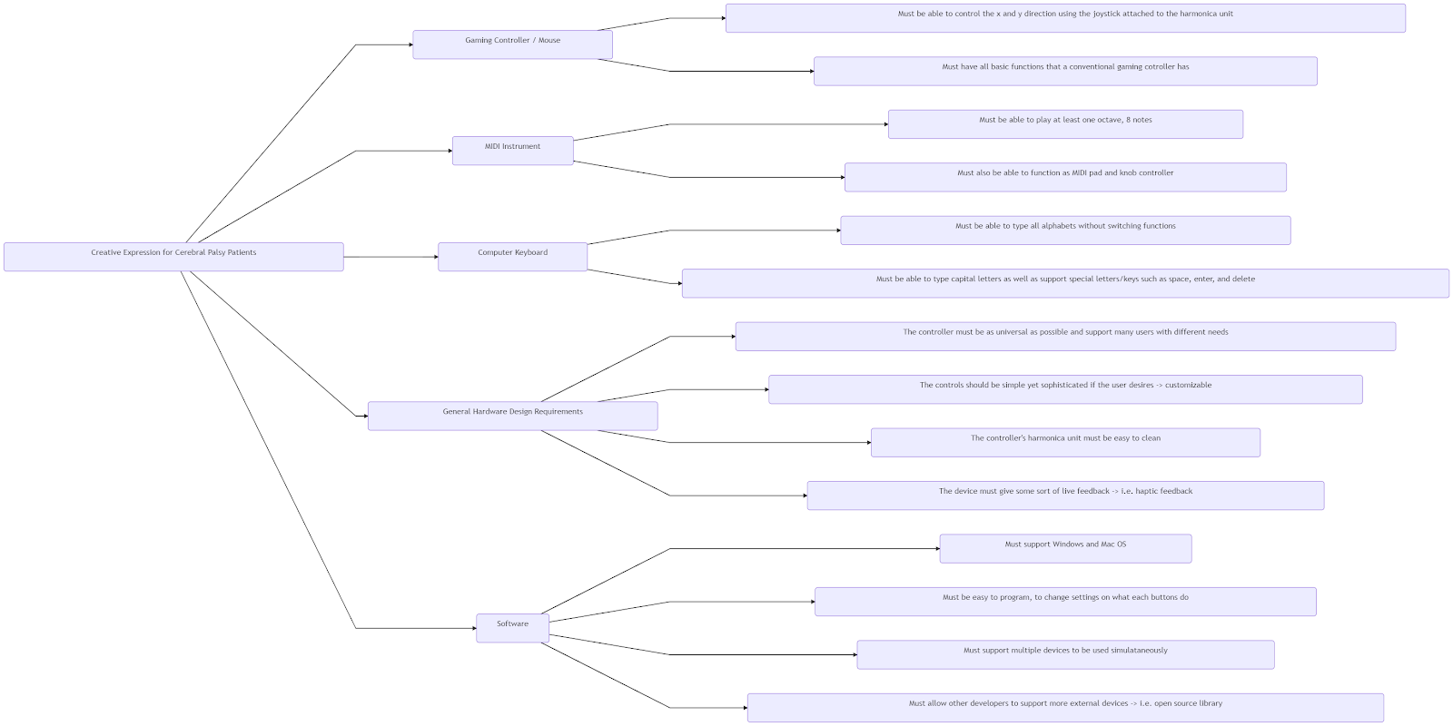
Our next step was starting a critical to quality analysis (CTQ) where we defined the critical aspects of each functionality. Initially, we did this separately, with Shu and I making our own analysis. Then, we evaluated each other's work and created a definitive CTQ analysis by aggregating the individual ones. The diagram below is our final CTQ showing the requirements for each functionality.
The full diagram can be viewed from the link below:
Creating this diagram was an important milestone. It opened the doors to the exploration of the components that would be needed to make all of these functionalities possible.
I know that getting an idea of our full CTQ is difficult from the diagram alone. For some of the requirements, we had long discussions to clarify what each of us meant. I’ve listed the details we discussed for some of the key requirements that are worth mentioning below.
“Must also be able to function as MIDI pad and knob controller”
We initially only had a MIDI keyboard in mind, but we realized that by adding a potentiometer to the device, it could also function as a MIDI knob controller and MIDI pad like in the image below.
Figure adopted from the image cited below.
(B&H Photo, 2020)
“The controller must be as universal as possible and support many users with different needs”
We know that cerebral palsy has a wide range of effects on motor controls, and this is different for everyone. Although we know that this device alone will not be able to support every user with cerebral palsy, we want to do our best to help as many people as possible. One way we’re planning to do this is to make everything, including hardware, electronics, and software open-source. By making everything open to the public, we believe that a community of users and developers could come together to share hardware and software customizations.
As we design our product, we will also keep in mind about universality. For example, we’ve already decided to use 1/4-20 UNC threads, the most common type of thread used in consumer-grade cameras. This will allow various camera accessories such as flexible tripods or stands to be used in conjunction with our device.
We believe that small design choices like this can add up to make our device as universal as possible. Additionally, we know that making this device truly universal is not possible, and perhaps this is the most challenging aspect in designing adaptive devices; however, we believe that creating a user and developer-driven community will give the best chance for this device to reach its full potential.
“The device must give some sort of live feedback → i.e. haptic feedback”
We added this to our CTQ after we had a mentor session with people from the UCPLA. One of the mentors, Aragna Ker suggested that having some sort of feedback to indicate that the device has taken action would be useful for the users. Instead of just hoping that the result will show up on the computer, it would be more helpful if the device gave out an indication that the device was used. As of now, we are considering adding haptic feedback similar to vibration motors in mobile phones.
“Must be easy to program, to change settings on what each airway do”
We plan on making a dedicated software to allow users to fully customize what each of the airways in the device does. We will have a “default template” of what each of the airways does, but should the users want to customize the device for different programs, we want to give them this option. For example, in many of the common web browsers, pressing CTRL + W closes the active tab. Typing this command through our harmonica unit would be difficult. Using the dedicated software, the user would be able to program the device such that when he puffs into the 13th airway, it would type out CTRL + W at once. Of course, this is just an example and the possibilities are endless. This feature would be especially useful for professionals that need to use programs that require shortcuts such as Adobe Photoshop.
“Must support multiple devices to be used simultaneously”
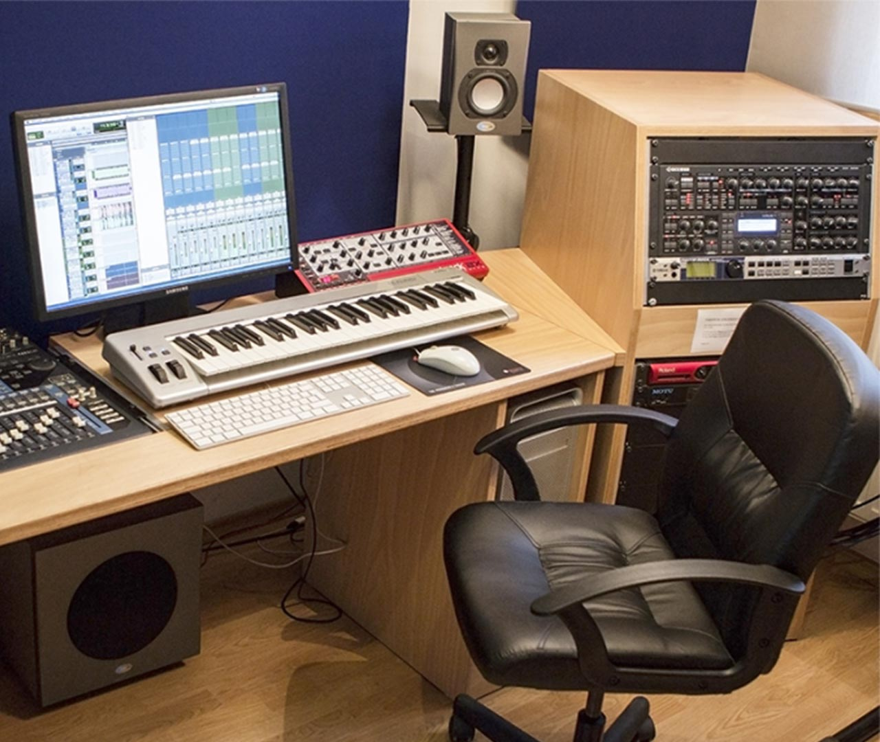
We know that the physical airways, joysticks, and the potentiometer built into one device may not be enough to fulfill the needs of every possible application. For example, in composing music in DAW (i.e. Garageband or Logic), many musicians like to have a MIDI keyboard in the front and a MIDI drum pad or MIDI knob on the sides.
(SAE Institute, 2020)
We want to allow multiple of our devices to be used together at the same time. For example, the device in the front could function as the MIDI keyboard while the device on the left side could function as a MIDI drum pad or a MIDI knob controller.
“Must allow other developers to support more external devices → i.e. open-source library”
We mentioned this briefly before, but we want to make our device as open as possible to allow other developers to expand the applications of this device. For example, there are many electric wheelchairs in existence. A user supported by a developer could customize the device so that it could also control the wheelchair as well. The source code or additional hardware required to do so could be shared within the user community so that others with the same wheelchair could make this modification as well. This of course not only applies to wheelchairs. It could apply to smart home appliances, other types of MIDI instruments or other everyday home appliances. A strong developer community behind our device will allow new functionalities to be added over time continuously while adapting to more consumer appliances that users with cerebral patients may want to use.
References
B&H Photo. (2020). MIDI Interface
https://www.bhphotovideo.com/images/images2500x2500/arturia_230501_minilab_mk_ii_1299531.jpgSAE Institute. (2020). Image showing a typical MIDI setup
from https://dr4s1fmfmn4kr.cloudfront.net/images/facilities/sae-leipzig-midi-studio.jpg -
Coming up With Our Idea
08/11/2020 at 07:39 • 0 commentsWe decided to give ourselves some time before our first video call meeting to thoroughly read the design briefs for each nonprofit challenge and think about ways to solve each issue. Then during the meeting, we discussed the benefits and drawbacks of each idea, debated on the feasibility of each idea given the time and resources we had available and contributed our thoughts. Below, we’ve summarized the discussion we had for the idea we decided to pursue as well as two other ideas we had.
Mouth Controlled MIDI/Game Controller/Mouse / United Cerebral Palsy Los Angeles / Shu
This device is an external computer accessory for patients with cerebral palsy and other disabled patients that struggle with fine motor controls. The device is controlled using the user’s mouth, head movement and breath. It will support multiple purposes for creative expressions and recreations. The primary functions of the device include being used as a computer mouse, gaming controller, keyboard and a MIDI controller (to play music using DAW software). Each of these functions can be switched by using predetermined breath gestures. For example, puffing into the harmonica from left to right would switch the device from the mouse function to a keyboard function. Also, this system could be expanded by adding additional devices on the sides to meet different needs of the users. For example, a musician using this system could have the main device in the front acting as the MIDI keyboard and the device on the side acting as a MIDI knob device. Such functions of what each of the puffs does will be fully customizable through an easy to use software that maps out this device visually.
![]()
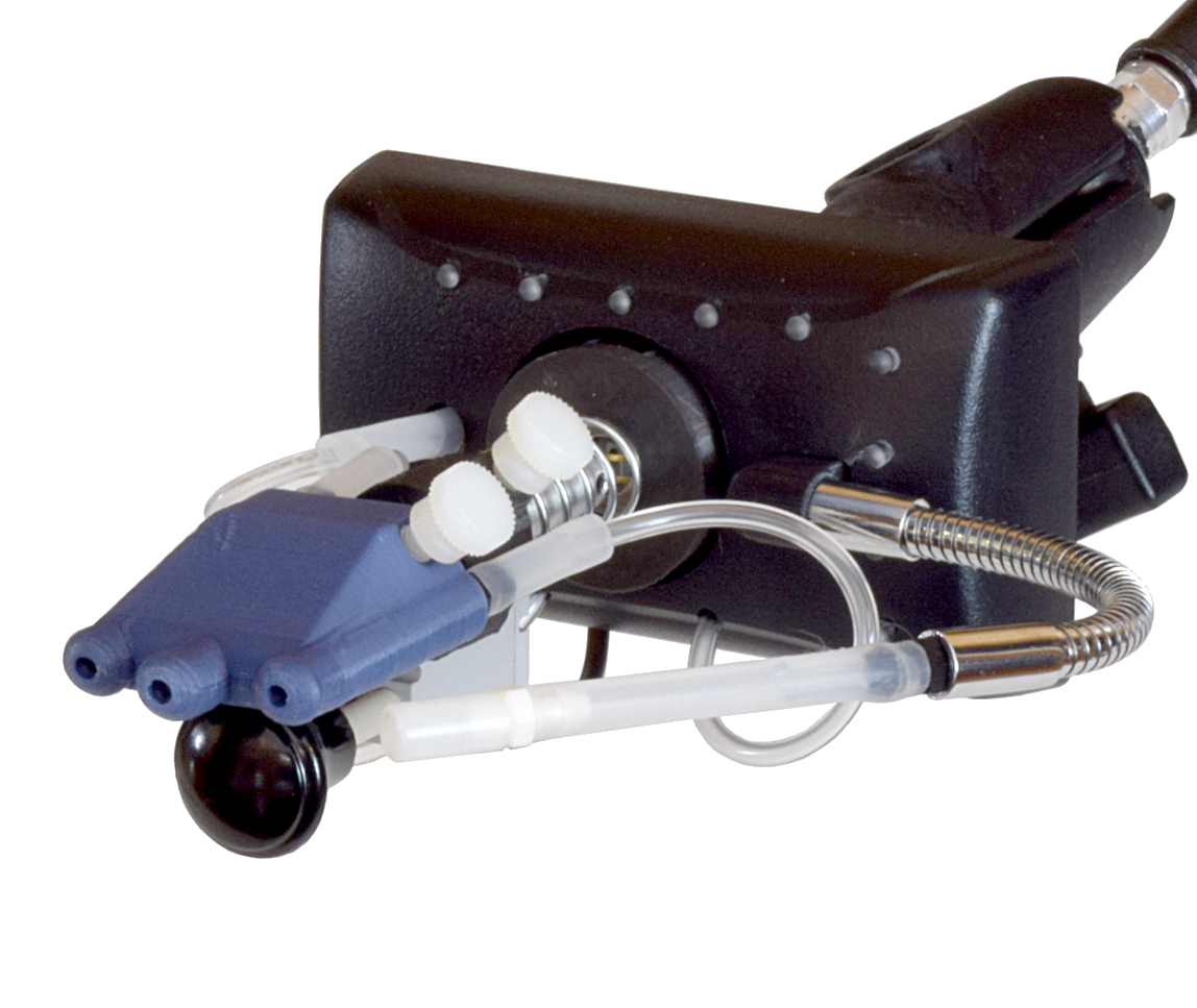
I came up with this idea after watching a TED talk called Disability Technology by Jeff Paradee. He introduced a sip and puff device that was specially designed for playing video games. This device has joystick that is controlled using the mouth to act as a computer mouse and an airway that allowed users to click on elements in a GUI environment. I instantly thought that this was one form of creative expression and wondered if this concept of sip and puff could be applied to other means of artistic expressions.
![]()
(Quadstick, 2020)
After some thoughts, my mind settled on creative writing, digital arts, music composition and of course gaming. The idea was to add more airways to add additional functionalities to the device. From observing that a MIDI device and a keyboard is just an array of buttons, I drew an analogy between this idea and a harmonica. The main source of inspiration for drawing this analogy was from seeing musicians play the harmonica hands-free while playing the guitar.
(Rowland Scherman, National Archives and Records Administration, 2020)
We saw some potential problems that could get in our way while prototyping this device. The first potential issue was how we were going to detect the sip and puff from the users. We initially thought about using an array of microphones to detect the breaths; however, after more research, we found that an air pressure sensor was more appropriate for this purpose. We also thought of other means to detect the change in airflow, and we’re still in progress of deciding what kind of sensor to use. Another potential issue was how a gaming joystick and the potentiometer was going to work together mechanically. We are still thinking of ways to overcome this problem.
Despite the potential issues we saw in our way, we believed that this idea was the most suitable project given the time and resources available. This project was challenging enough for us, but we could still see the light at the end of the tunnel. It was a project we felt we could utilize both of our skills both of us had developed over the years.
Smart Text to Speech Glass / United Cerebral Palsy Los Angeles / Shu
This is an adaptive tool designed to facilitate communication for cerebral palsy patients and other patients with similar needs. I saw the need for such a device after seeing many heavy and bulky communication adaptive devices that constructed plain and boring computer-like sentences. The device is driven by a small and affordable microcontroller such as an Arduino or a Raspberry Pi Zero and uses eye-tracking technology to gather user input. The glass has a mini projector to project suggested sentences and words on to the glass, similar to Google Glass. In addition, the glass also has a microphone built in to improve sentences and words suggestions based on the context of the user’s conversation using machine learning.
![]()
Although this idea seemed feasible at first, there were a few problems that would have to be overcome. The first and the big one is how the eye-tracking system would work. None of us had seen eye-tracking that worked at such close proximity to the head. We discussed other ways of controlling the device, but we felt that without the eye-tracking feature, the device would not be as convenient. Another potential problem is the projection system. We know how such technologies work, but we could not see a realistic way to prototype this with the resources we had available. This is not to mention our lack of experience in machine learning to build the auto word and sentence suggestion feature. We thought that this idea is technologically feasible, but we would need a longer time scale and learn more advanced skills to build even the proof of concept, all of which were not realistic for us.
Digitally Controlled Exothermic Reaction Medical Fluid Warmer / Field Ready / Pato
Pato knew that part of what made medical fluid warmers expensive was the use of precise heat elements and control units. The idea for this device was to instead use an exothermic chemical reaction as the heat source for warming the fluid. Then using a special material that changes its heat conductivity as a function of the voltage applied, the heat that gets transferred to the fluid could be precisely controlled.
![]()
The biggest issue with this idea is that we couldn’t think of what this ‘special material’ could be. We found out that a research group at the Sandia National Laboratories had found a way to alter the conductivity of a material known as PZT (lead zicronate titanate) by varying electric voltage. However, this was achieved in a lab and it had never been put into a real world use. After some consultation with Pato’s friend who is a chemical engineer, we also considered controlling other aspects of the reaction. Although these methods seemed more feasible, we concluded that controlling an exothermic reaction precisely by digitally controlled means would be more costly than conventional methods. This was without even considering the difficulties associated with heat loss from the system and varying reaction times of the chemicals in a non-laboratory setting.
References
Quadstick. (2020). Original Quadstick Game Controller
Rowland Scherman, National Archives and Records Administration. (2020). Joan Baez and Bob Dylan, Civil Rights March on Washington, D.C.
https://upload.wikimedia.org/wikipedia/commons/c/c7/Joan_Baez_and_Bob_Dylan.jpg
-
Introduction from Pato
08/11/2020 at 01:51 • 0 commentsHello everyone, Pato here! I’m so excited to be starting this project with my good friend Shu.
I graduated from Electro-mechanical engineering last year, and since then, I’ve been looking for experiences to complement my professional development. As Shu mentioned, I have a great passion for electrical engineering, but I also love prototype design.
When Shu told me about this project and invited me to work together as a team, I couldn’t say no. I know that he is a very talented maker, and I’ve learned a lot from him. I knew this was an opportunity to keep honing skills I’m interested in, and most importantly, to create something of value and transcendence.
I’m confident that whatever comes out of this collaboration will be a product with a meaningful impact. Let’s get to work!
Magpie MIDI - An Adaptive MIDI/Interface Harmonica
Creative expression tool for cerebral palsy patients


 Shu designed a simple air hole to measure different interactions with the sensors. As you can see in the picture below, we chose a square air hole to replicate that of an original harmonica and added a pressure relief exhaust orifice at the back of the air hole. The dimensions of these simulations were also evaluated using fluid dynamics principles (Bernoulli’s Principle).
 Now that I had tested some of the detailed parts I was concerned with, I was confident that I could design the entire base unit. The first draft of the design took about two hours. For now, I decided to use small wood screws to hold the components together. I plan on considering using other methods for the assembly process later.
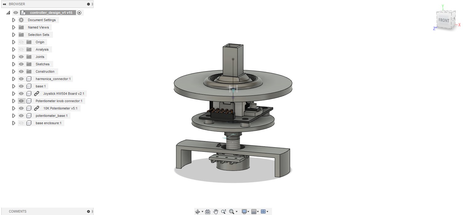 All of the components printed without any major issues, except one. The component I had trouble with was the joystick handle. This component was both difficult to design and fabricate. This component had to be designed so that wires from the circuit board inside the harmonica unit could pass through the component while providing the snug fit to the joystick module. In terms of fabrication, I first tried 3D printing the component with an FDM printer, but as you can see in the photo, the outer part was too thin. So, I tried printing this component with an SLA printer. It worked but I had to re-print three times and make additional adjustments. As you can also see, in the final version, wires could pass through without affecting the snug fit to the joystick module.
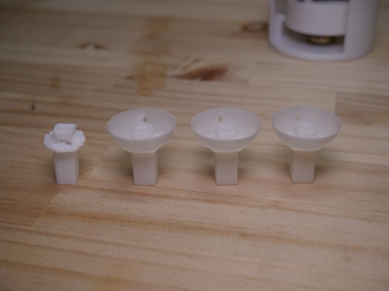
 I also came across another issue. The rotary joint between the joystick module and the potentiometer wiggled significantly when the joystick was moved. I should have noticed this in CAD, but it’s always a challenge to think about how things are going to work in the real world versus what it looks like in CAD.
 To make the platform, which the potentiometer module sits on more stable, I added a circular guide around the potentiometer to provide additional support.
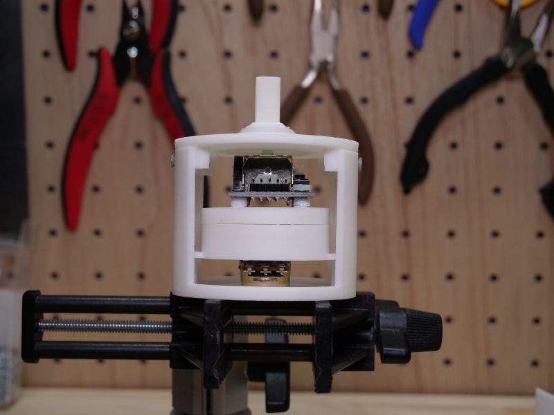
 It took a while to make adjustments, wait for the 3D printers, and to test fit the components; however, all this patience paid off at the end and I was satisfied with the result. The video below is a short demo of the base unit.


