 ArsenioDev
-
Q1 2017 Rocket active stabilization system update; Finally have working PID for positional control of a DC motor! New gear and the first program sponsor!
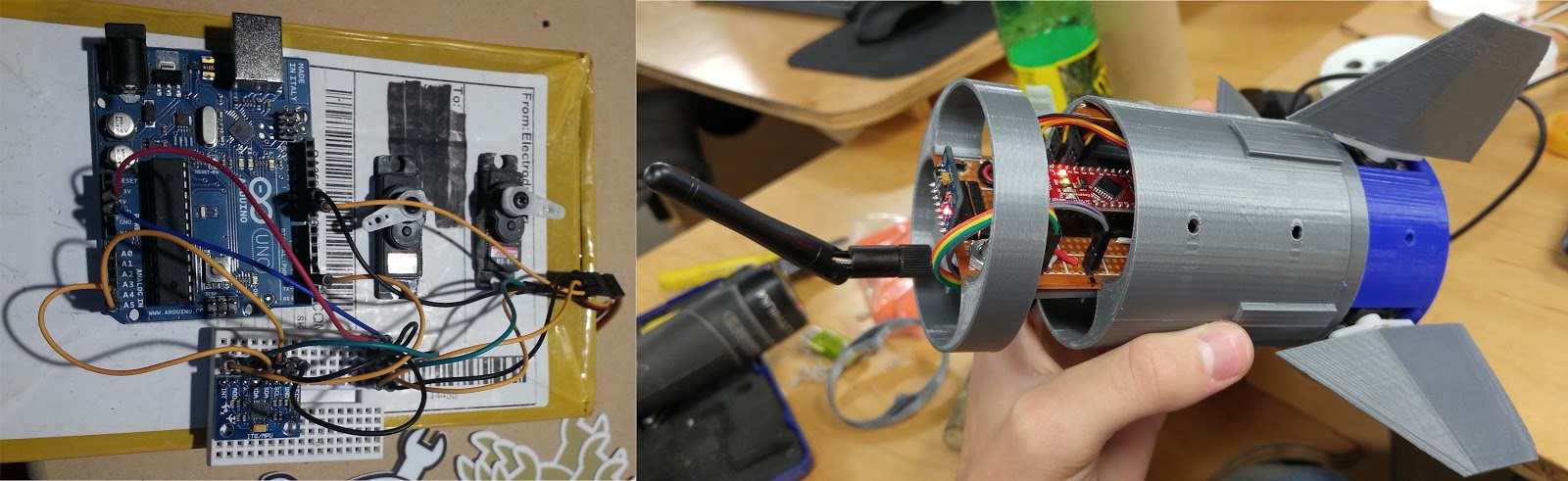
07/14/2017 at 18:53 • 0 commentsAfter nearly 4 and a half months of late nights, caffeine fueled jam sessions, one livestream(more on that later!) and more frustration than anticipated I FINALLY figured out implementation of PID for positional control of a DC motor with an encoder. More details after the break including a breakdown of problems I ran into, some shiny response graphs and most importantly; SOURCE CODE!?!?!
![]()
---------- more ----------In working towards a positional control system, the first order of business was to go for the most basic of controllers; Bang-Bang. Dead simple to implement but not without numerous shortcomings. Several of these removed it from even consideration of the flight unit due to possibility of overcontrol or destructive airframe resonance. Airframe resonance would start as a flutter in the fins but spread to the stabilizer oscillating on the front of the rocket before finally leading to a full half of the body wobbling about the split for parachute deployment and snapping the rocket in half mid-flight. Another nightmare scenario is overcontrol, where the system attempts to correct course changes but turns itself into a kinetic hazard as it passes the +- 5 degrees off vertical allowable range for safe flight or worse goes sideways and WAY off course.
![]() A Bang-Bang control system is dead simple, if the value is not reached, keep going until it's passed at which point you go backwards. The issue arises in that the system runs at full tilt and will always overshoot unless there is a lot of inertia in the system(e.g. a flywheel or significant thermal mass) leading to the oscillation around the target value as depicted in the figure below. During my initial implementation of the controller, I had a serious problem where the system would appear to be on target and tracking but would start spinning as the counts went from the expected range (0-300) to around 32,767 before flipping out. This is an indicator of unsigned int overflow but limiting the system read range to 300 did nothing to minimize this issue. Rereading the documentation, I realized that the encoder pins were not both on the hardware interrupts and that was causing it to miss a lot of counts since A phase was on HWINT1 but B phase was on a regular pin set as an interrupt. Moving B phase to HWINT0 fixed this problem. Attempts to lower the jitter around the target included decreasing drive PWM and testing deadzones and braking but none of those worked to the extent required for flight confidence. As I had eliminated bang-bang from flight consideration, I turned to the more complicated but also FAR superior PID controller which was a heck of a challenge.
A Bang-Bang control system is dead simple, if the value is not reached, keep going until it's passed at which point you go backwards. The issue arises in that the system runs at full tilt and will always overshoot unless there is a lot of inertia in the system(e.g. a flywheel or significant thermal mass) leading to the oscillation around the target value as depicted in the figure below. During my initial implementation of the controller, I had a serious problem where the system would appear to be on target and tracking but would start spinning as the counts went from the expected range (0-300) to around 32,767 before flipping out. This is an indicator of unsigned int overflow but limiting the system read range to 300 did nothing to minimize this issue. Rereading the documentation, I realized that the encoder pins were not both on the hardware interrupts and that was causing it to miss a lot of counts since A phase was on HWINT1 but B phase was on a regular pin set as an interrupt. Moving B phase to HWINT0 fixed this problem. Attempts to lower the jitter around the target included decreasing drive PWM and testing deadzones and braking but none of those worked to the extent required for flight confidence. As I had eliminated bang-bang from flight consideration, I turned to the more complicated but also FAR superior PID controller which was a heck of a challenge. ![]() A proportional–integral–derivative (PID) is a controller that calculated the difference between setpoint and current variable and corrects based on the three terms (Kp, Ki, Kd). I'm going to leave the rest of the explanation to Brett Beauregard who wrote the FANTASTIC library I'm using. Early attempts at implementing the PID by taping the well-respected PID library into the bang-bang controller led to frustration due to calculated outputs being WAY off the expected. The odd thing was outputs either sharply moving around but not passing 255 or locked at that value. As I was hitting the limits of my coding knowlege I called up Joe Barnard of Barnard Propulsion Systems (the OTHER active stabilization guy on the internet) to see if he would be able to help figure out what was going wrong. Unfortunately neither of us was able to make any sense of why it wouldn't work even after 3 hours of trying to debug. It wasn't until I found a very different method of driving the TB6612FNG in a Pololu robot, specifically the 3Pi that I finally got the system working. Instead of pulling the direction pins to logical 1/0 and driving the PWM pin I pulled PWM HIGH, and drove both directions with PWM signals, which puts the driver in half-brake mode and only needs 2 IO pins instead of 4. The magical code that finally got the system working is as follows;
A proportional–integral–derivative (PID) is a controller that calculated the difference between setpoint and current variable and corrects based on the three terms (Kp, Ki, Kd). I'm going to leave the rest of the explanation to Brett Beauregard who wrote the FANTASTIC library I'm using. Early attempts at implementing the PID by taping the well-respected PID library into the bang-bang controller led to frustration due to calculated outputs being WAY off the expected. The odd thing was outputs either sharply moving around but not passing 255 or locked at that value. As I was hitting the limits of my coding knowlege I called up Joe Barnard of Barnard Propulsion Systems (the OTHER active stabilization guy on the internet) to see if he would be able to help figure out what was going wrong. Unfortunately neither of us was able to make any sense of why it wouldn't work even after 3 hours of trying to debug. It wasn't until I found a very different method of driving the TB6612FNG in a Pololu robot, specifically the 3Pi that I finally got the system working. Instead of pulling the direction pins to logical 1/0 and driving the PWM pin I pulled PWM HIGH, and drove both directions with PWM signals, which puts the driver in half-brake mode and only needs 2 IO pins instead of 4. The magical code that finally got the system working is as follows;void pwmOut(int out) { if (out > 0) { analogWrite(AIN1, out); analogWrite(AIN2, 0); } else { analogWrite(AIN1, 0); analogWrite(AIN2, abs(out)); }}More tuning and testing needs to be done in addition to implementing servo-protocol control but this is VERY good news since I had been holding off on further system hardware work until I'd solved the problem of positional motor control. Hold on, I know you were wondering "Hey wait a minute you said something about source code, yet you said this project is likely under ITAR, what gives!?!" no? Well you're not exaaaactly wrong. I won't be sharing the source code for the rocket controller or other fun parts but CAN share the positional control since it's not regulated and a good lesson in control mechanics. The primary reason I'm sharing this is because all the existing material out there is either absurdly vague or headache inducing with uncommented code and very strange implementations of parts. So as a firm believer in open source and learning from analyzing other's code, I have adopted the beerware license on this and my other projects that will be getting code releases. My code is available on my GitHub for everyone to use and learn from. Timelapse of my fighting with the code has also been uploaded from one of my later Twitch streams.![]() Initial test version showing issues with PID output (orange)
Initial test version showing issues with PID output (orange)![]() The magical sight of a working PID plant in action.
The magical sight of a working PID plant in action. ![]()
Too much gain![]()
Locked on and holding positionNow as some of my longer-term readers will know due to me living farther out from civilization I'd been having some godawful internet. 80gb/month and horrifically slow (<1mb/s) is REALLY not conducive to content creation or getting much done. However the big red ISP has decided to bring back uncapped internet which has been WONDERFUL! From limping along and hitting the 80gb cap frequently, now comfortably burning 300+ a month and oddly the speeds are around 10mb/s. Now with all this power, I've done something that was discussed for a long time: Livestreams! From the stream lair I did a 2 hour quick CAD cloning of the Pharah Mechaqueen rocket from an image to get a feel for streaming, and will definitely be doing more soon including Live from the lab. More work needs to be done on the upstream settings, audio levels and recording but it's a start.
![]()
![]()
![]() I also decided to invest a bit more into my content this year and bought myself a proper DSLR during the black friday sale and have been playing around with it. After a ton of research, the Nikon D3400 stood out above the rest and the black friday deal on the full starter set made it a no-brainer. Now the videos and pictures for the blog and youtube channel will get a dramatic increase in quality. Below are some high resolution (6000x4000) images, previously had just been shooting with my LG G4 which has a great camera but can't compete with the MUCH larger sensor and aperture of a full size camera.
I also decided to invest a bit more into my content this year and bought myself a proper DSLR during the black friday sale and have been playing around with it. After a ton of research, the Nikon D3400 stood out above the rest and the black friday deal on the full starter set made it a no-brainer. Now the videos and pictures for the blog and youtube channel will get a dramatic increase in quality. Below are some high resolution (6000x4000) images, previously had just been shooting with my LG G4 which has a great camera but can't compete with the MUCH larger sensor and aperture of a full size camera.![]()
![]()
![]()
![]()
![]()
Another VERY important update is that I FINALLY got a sponsor! Pololu has stepped up and contributed a full set of high power micro gear motors and encoders to match. These will be integrated into the testing version and likely carried onto the flight system assuming that everything checks out in control authority testing and launch confidence checks are green.
-
Prograde burn; I quit my day job to work at NASA
02/02/2017 at 13:33 • 3 commentsYes you read that right, as of January 30th I am working at NASA Goddard as a student researcher in the earth sciences wing, specifically on the 4U Laser Hetrodyne Radiometer cubesat as a hardware/software engineering intern.
![]()
As for how on earth I landed here the story is convoluted but to make a long story short; An internet friend who works at NASA thought I'd be a good fit for his intern army and after 6 months of limbo where it was uncertain if they'd be able to get me, I finally interviewed and was in. Some of the key points of consideration were that I had a multifaceted skill set of hardware and software, in-depth documentation of my work on the blog, familiar with GitHub and lastly, open to learning new roles and skills.
Work will continue on the stabilizer, have no fear, as the motor control is coming along nicely with a basic bang-bang control plant done.
Ad Astra
Arsenio Dev -
Late(r) 2016 update; on redesigns and disclaimers
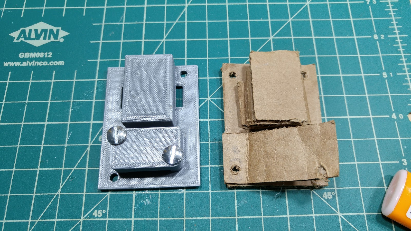
11/02/2016 at 00:31 • 0 comments![The old and the new]()
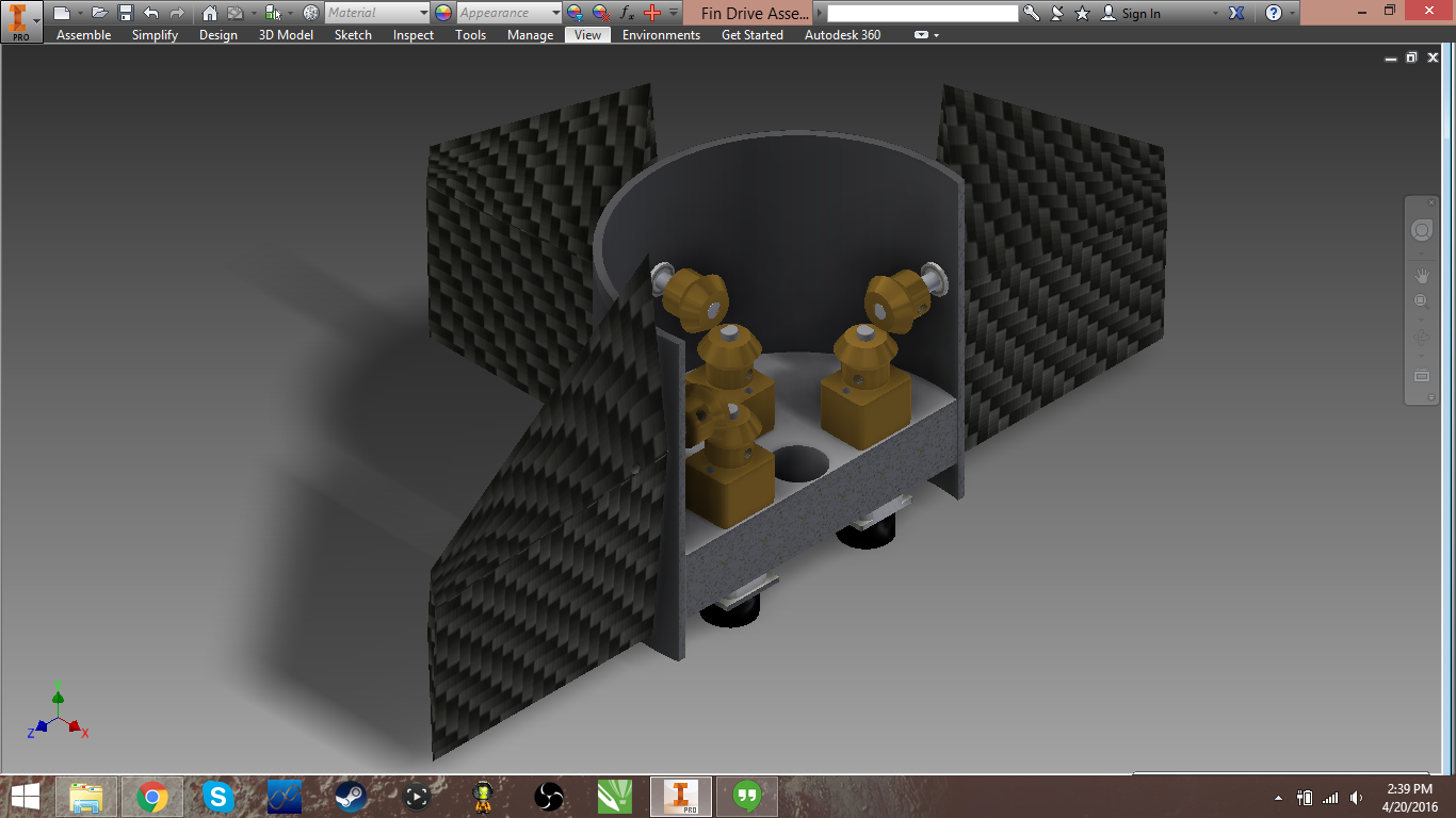
Update time has rolled around again now that a good chunk of progress is completed on the Arduino based rocket stabilization system. This has taken a while since I've been busy with not only work but also getting the A+ certification in computer repair and completely reworking my current workstation. After much discussion with several other rocket tinkerers, the conclusion was reached that stresses on the servo spline itself would be quite considerable and may result in damage or inoperability. Based on force distribution I surmised that flanged bearings embedded in the system shroud tube would function as not only supports but also as smooth rotation points. With the challenge of a new fin drive train in mind, I set to brainstorming. My first thought was to use linkages connecting the servo to the actuation shaft, though it would increase the diameter of the system unless the servos were staggered which would also increase the overall height of the system. Stepper motors were considered, however as I was unable to find suitably sized units and the common 28byj-48 had too low precision and torque this too was eliminated from consideration. After those two ideas were discarded, it was relegated to the back burner while I had work. The breakthrough was about a week later, while browsing patents looking at missile fin drives I noticed an old Raytheon control segment used bevel gears to transfer the motion and that became the seed for the new design.
As a reminder, this project MAY fall under ITAR restrictions and as I do not have the funds to file for verification, I am playing it safe by not sharing code or CAD. This system is not designed nor intended to be used as a weapon, rather just keeps a high-power sport rocket flying vertical. No I will not help you port my work to be used in mortars/missiles (yes people have seriously asked this). I am doing this project as a personal challenge to learn new skills, processes and to broaden my project scale horizons, I harbor no malicious intent.
![Original sketch for new design using pushrod linkages and servos, scrapped]()
![Initial sketch of DC motor and bevel gear based drive system]()
With bevel gears as the motion transfer solution in mind, I thought back to motors and remembered that there are small diameter low voltage geared motors with micro encoders available on Pololu and the other usual sites. I did consider using high end Faulhalber motors with built in encoders but gave up when I saw the prices were $25 a piece, completely out of my price range. With that sorted I roughly sketched a layout for the system. Once the motors were sorted, then came the second biggest challenge; the bevel gears. I tried the usual distributors, McMaster, KHK, Robotshop, RS and eBay all to no avail. Motionco did sell acetal(plastic) gears but in this case metal is the way to go and they were UK based. I called several gear manufacturers but their quotes ranged from the low to mid hundreds which is WAY out of my price range. Slightly disheartened I turned to the last place I could think; Aliexpress. Thankfully, there are gears available though they are a bit expensive ($16/pair of which $4 is shipping that cannot be combined for some reason). The geartrain ratio between the motor and the fin output is 1:1 as is standard with most bevel gear configurations. Now that the basics for the power transfer system were locked in, I drew block diagrams and crunched the numbers for the encoder precision which came out to be .3deg/pulse on the output on the 1:100 geared 6V motor. Bearings were much easier since 3mm bores are a common dimension, a quick eBay search yielded a bag of ten 3x6x2.5 flanged bearings for well under $20.
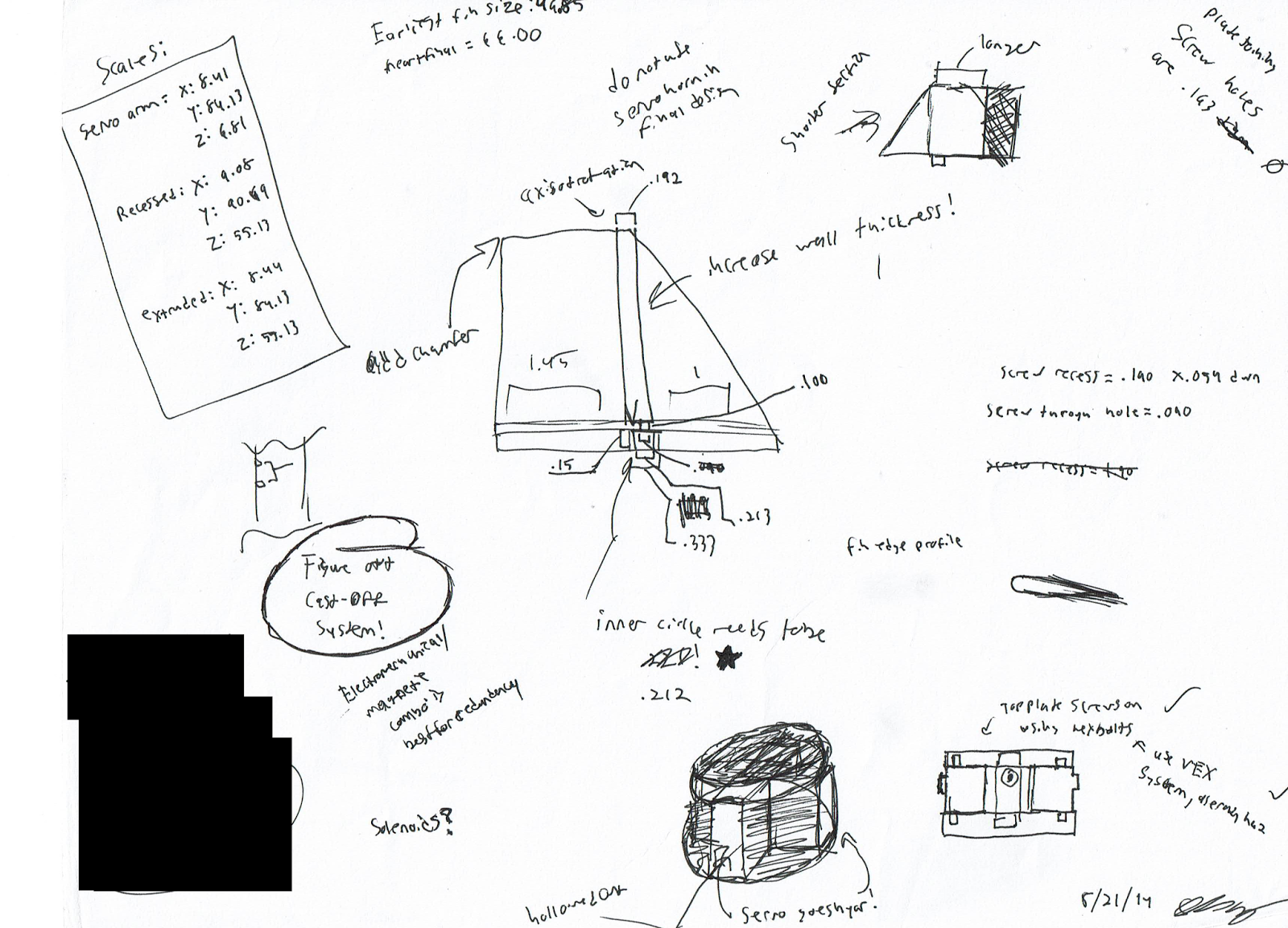
![Basic system block diagram with in-progress notes [Blackbox project note censored for safety]]() Armed with the sketches and an idea of the final goal, I set to constructing CAD models for future 3D printing. In the first revision I decided to try making it air frame compatible with the current system for drop-in usability and interchangeability. However, once the model was complete I noticed that there was a LOT of room for miniaturization with all the space between the motors, output shaft and side walls. In total, I was able to carve off 28.5mm bringing the total diameter down to 47.72mm(1.879in) which is 62% smaller than the initial version. The smaller diameter means that cheaper blue tube air frames can be used in the flight and testing versions. Another aim of shrinking the size and weight is so that smaller and cheaper engines are able to be used that also do not require a L2+ high power rocket certification. After asking around and talking to none other than George Gassway (Sun-based stabilization) I found out that I CAN launch at NAR sites and not have to head out to the desert to fly.
Armed with the sketches and an idea of the final goal, I set to constructing CAD models for future 3D printing. In the first revision I decided to try making it air frame compatible with the current system for drop-in usability and interchangeability. However, once the model was complete I noticed that there was a LOT of room for miniaturization with all the space between the motors, output shaft and side walls. In total, I was able to carve off 28.5mm bringing the total diameter down to 47.72mm(1.879in) which is 62% smaller than the initial version. The smaller diameter means that cheaper blue tube air frames can be used in the flight and testing versions. Another aim of shrinking the size and weight is so that smaller and cheaper engines are able to be used that also do not require a L2+ high power rocket certification. After asking around and talking to none other than George Gassway (Sun-based stabilization) I found out that I CAN launch at NAR sites and not have to head out to the desert to fly.![First version of gearmotor design, prior to miniaturization]()
![Closeup of miniaturized version, still needs a few tweaks.]()
Post-miniaturization I realized that using motors with encoders will result in relative positional control compared to the absolute positional control that the prior servo version had. Thinking on the problem led me to use potentiometers to supplement the encoders so I don't get off-center fins on startup leading to air frame destruction. The addition of the potentiometers adds an additional layer of complexity to the already highly involved code that will be controlling 6 PID loops for the motors and stability control. The code will be the biggest challenge for this whole project, combining Kalman filters, multiple PID loops, a whole control system and then on top of all that, a telemetry down link. For the positional motor control, I came across HomoFaciens' incredible videos on discrete servos, arduino based servos and encoder digital servos of which I will be forking his code into my system. It's currently quite a bit out of my comfort zone, though I am studying control theory on my own, taping code examples together and hoping I have it right since I do not have any hardware in front of me due to costs. Speaking of costs, crappy back of the napkin math prices this new system around $170(if all parts are bought from China) whereas the servo based version would be nearly $240 if I were to buy all the parts new, a whopping 75% savings. Each of the Hitec HS-82MG servos I used previously are about $20 each at standard market rates while the motors with encoders are going for $9.50 each thanks to the far east's cloning. If all the motors, encoders and drivers were purchased on Pololu the cost for that alone would be $99.05, and that does not include the microcontrollers, 8 bevel gears or the potentiometers, but would have known quality parts. That option is too expensive for a testing version but may be justified for the flight rated system stack. Unfortunately, due to being hit with an unexpected car repair bill among other expenses on my student budget has put buying parts for the project temporarily out of the question. I've been tempted to start a GoFundMe or Patreon to offset the costs of the projects but I always stop short of launching because I feel like a dick asking for other people's money to fund my personal projects. If readers want to donate to help offset the costs of development, there is a button in the left sidebar if they so desire.
Thanks for reading this update, as a bonus I've included more process sketches and as a special treat; a scan of the notebook page that started this whole project.
![CAD assembly of new gearmotor based design]()
![]()
![]()
![]()
![]()
-
First 2016 update; now with proper fins and a mockup
02/24/2016 at 00:44 • 1 commentWith 2016 well underway it's time for the first update on the state of the stabilization system!
First off, apologies for the massive delays this post has had, was originally slated for mid-Jan launch but between job hunting and other stuff I've been hitting delays and trouble at every turn. Since last semester ended on Dec 18th, I'd been going to TechShop pretty much every day until Jan 18th making massive amounts of progress.
![]()
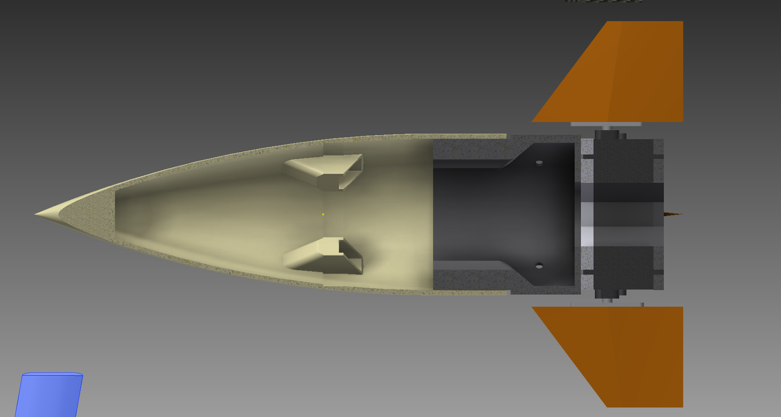
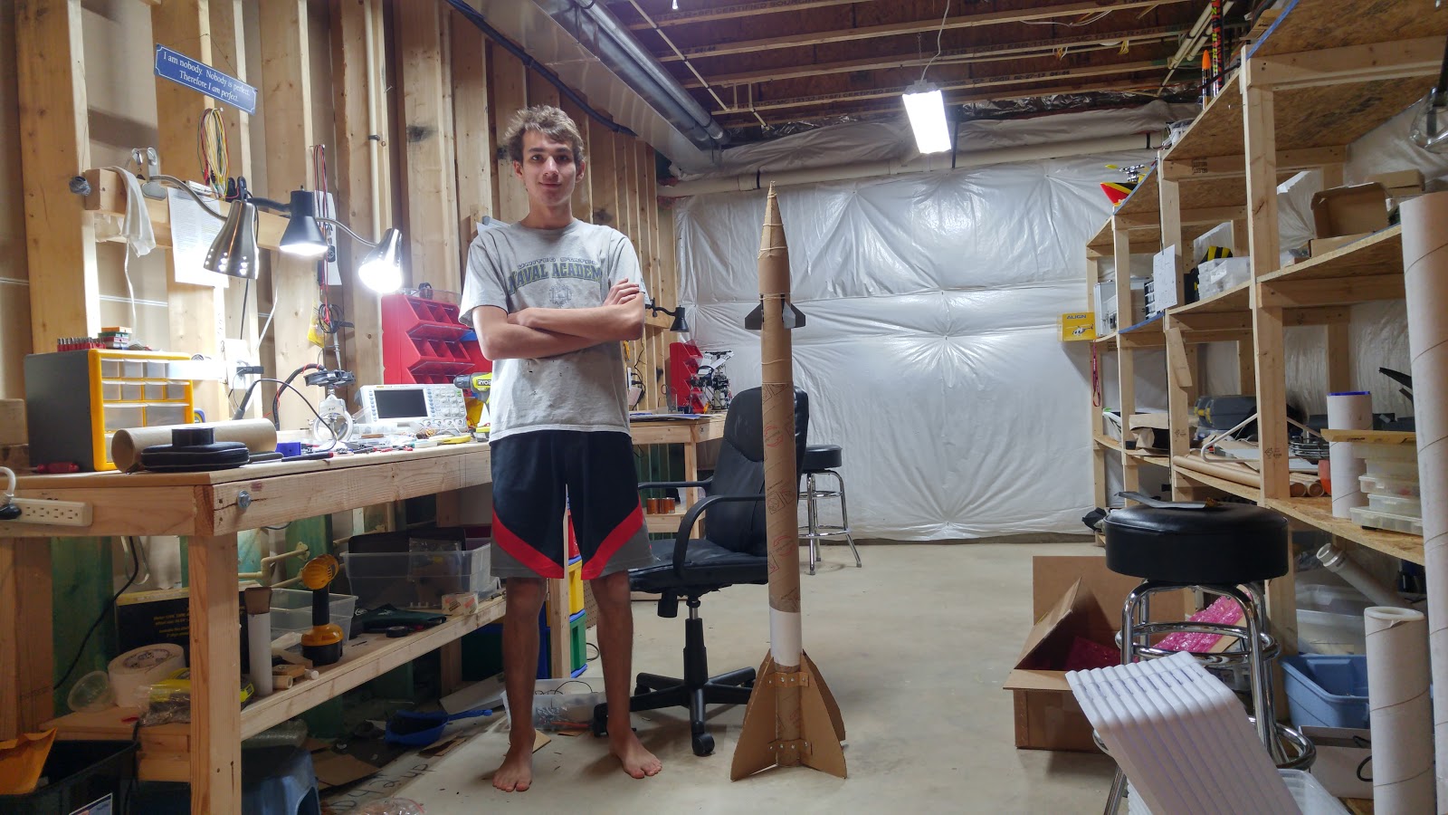
The demonstration mockup was constructed to not only have a physical representation of the final assembly but also to familiarize myself with layout and wiring inside a confined space which is new territory to me. It is constructed out of 3 inch ID cardboard mailing tubes and has fins cut from standard cardboard bolted on, nothing special or lightweight due to this not being the final flight model. The overall mass of this version is 1.48Kg of which 452g is the stabilization system module. Testing and flight versions will be constructed out of "Blue tube" for it's superior durability and lighter weight though at much higher cost ($30/4 feet, whereas the tubes I'm using I salvaged from the scrap pile for free)
![]()
![]()
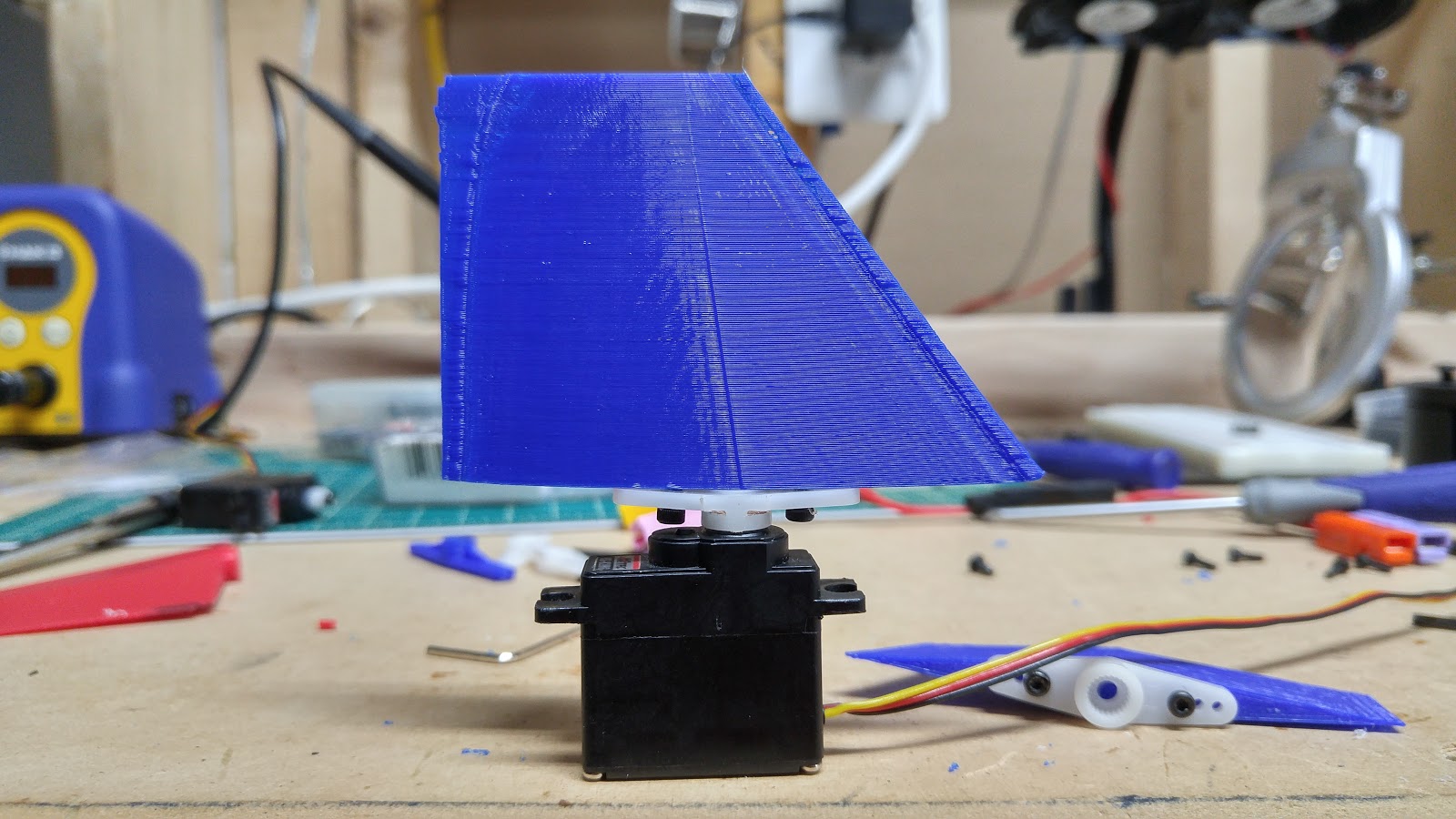
Some of my longer term readers may remember how much difficulty I was having with figuring out a method for attaching a fin to the servo spline, trying everything from printing a horn to trying integration of a round arm to no avail. In the end, I decided to stop trying to reinvent the wheel and rework an older design to bolt onto a premade servo horn. These are designed in standard diamond hypersonic form with the axis point 3/4 up the mean aerodynamic chord. Due to the mounting method of fins bolting directly onto the horn, installing these after the servos are in the body tube is impossible, forcing me to have a slot-in module that is held in place with bolts. The slots perform an additional function of being mechanical endstops for the fins to prevent an overcontrol instance(in theory). Sadly, two of the scavenged servos finally kicked the bucket and a full new set is going to cost me $72 ($18/HS82MG) which is FAR out of my frayed kitestring budget which has dwindled to nearly zero as of late. If any of my readers know how to get in contact with Hitec for a sponsorship or how to get parts donated to a student project it would be greatly appreciated if you would drop me a line.
![]()
![]() The integration can for my system needed to be reworked due to being a bit too small to fit in the 3 inch inner diameter body tube. I retained the previous method of servo containment and mounting, just upscaled a bit and added bolt holes for attaching to the airframe, in addition to adding a forward riser to hold the control board in place and provide a nose cone mounting flange. Making sure this has a slightly snug fit is key, as internal movement can instigate a self-amplifying and destructive resonant wobble. Two slots with gentle slopes leading up were employed in this version.
The integration can for my system needed to be reworked due to being a bit too small to fit in the 3 inch inner diameter body tube. I retained the previous method of servo containment and mounting, just upscaled a bit and added bolt holes for attaching to the airframe, in addition to adding a forward riser to hold the control board in place and provide a nose cone mounting flange. Making sure this has a slightly snug fit is key, as internal movement can instigate a self-amplifying and destructive resonant wobble. Two slots with gentle slopes leading up were employed in this version.![]()
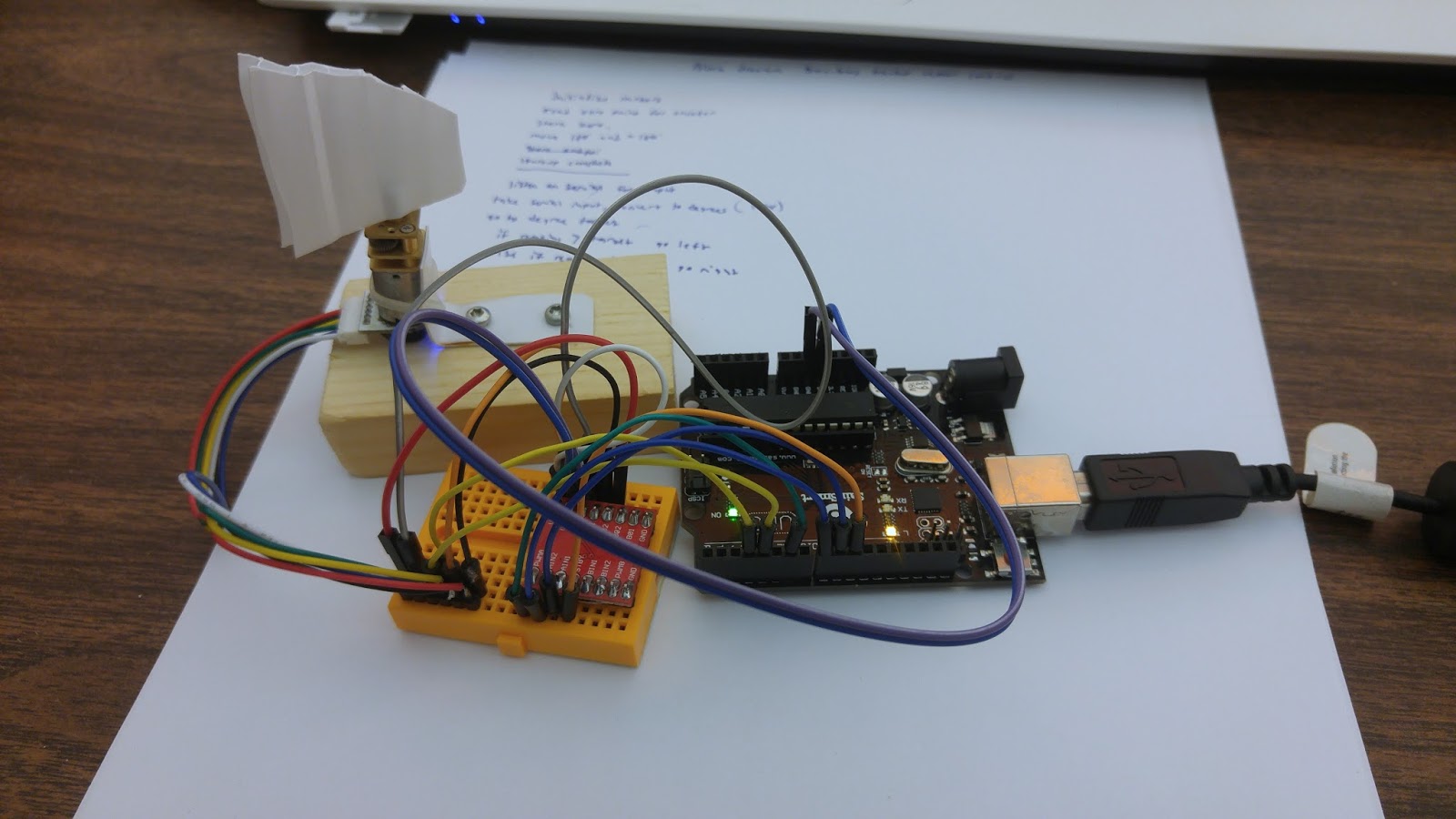
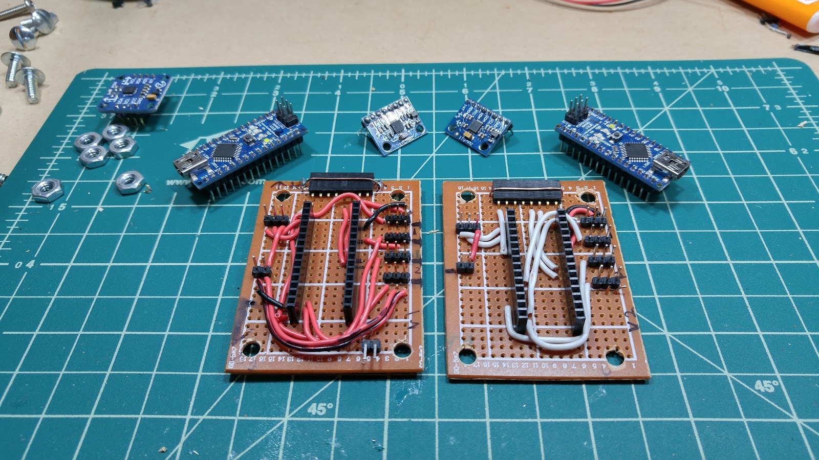
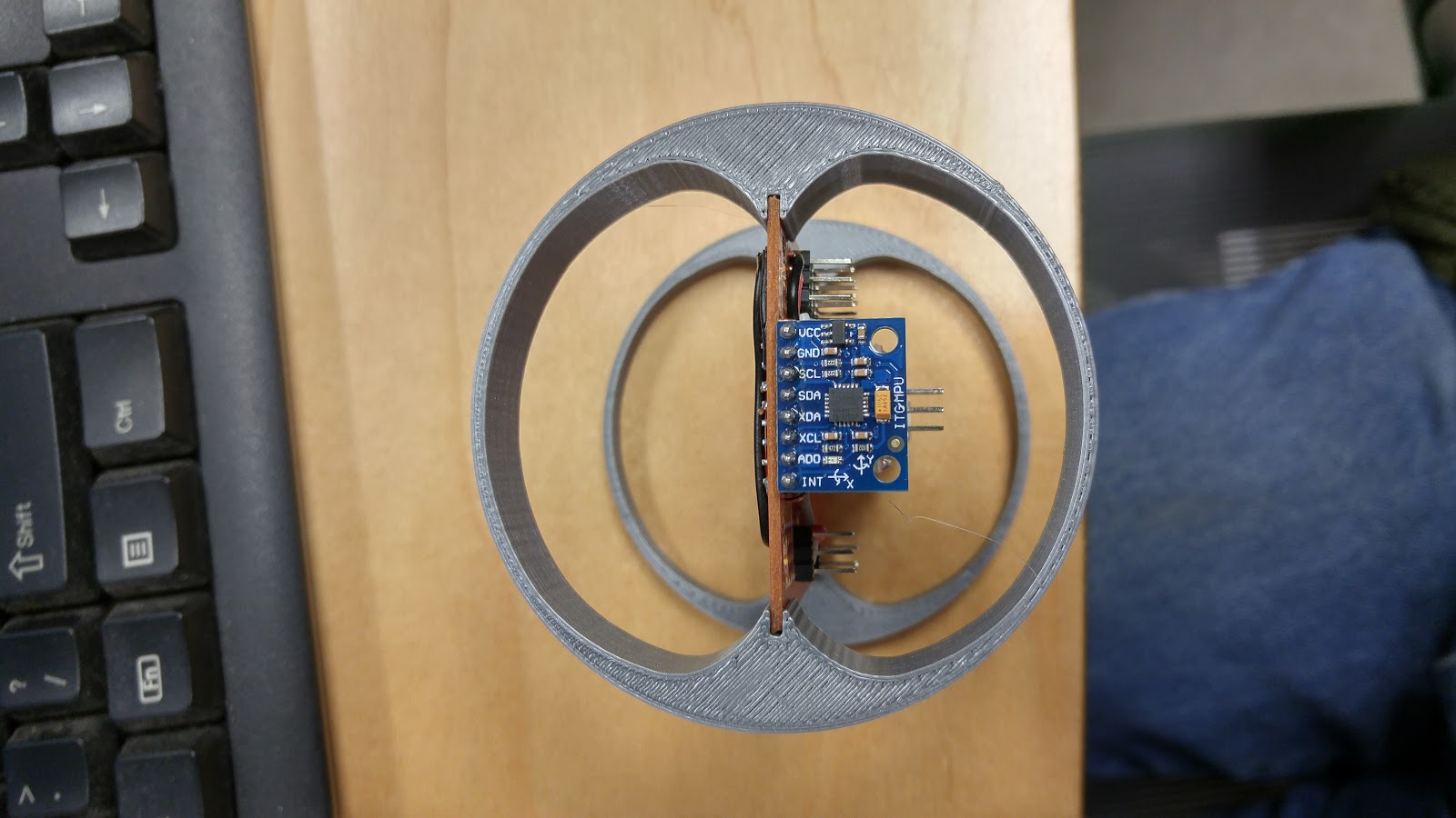
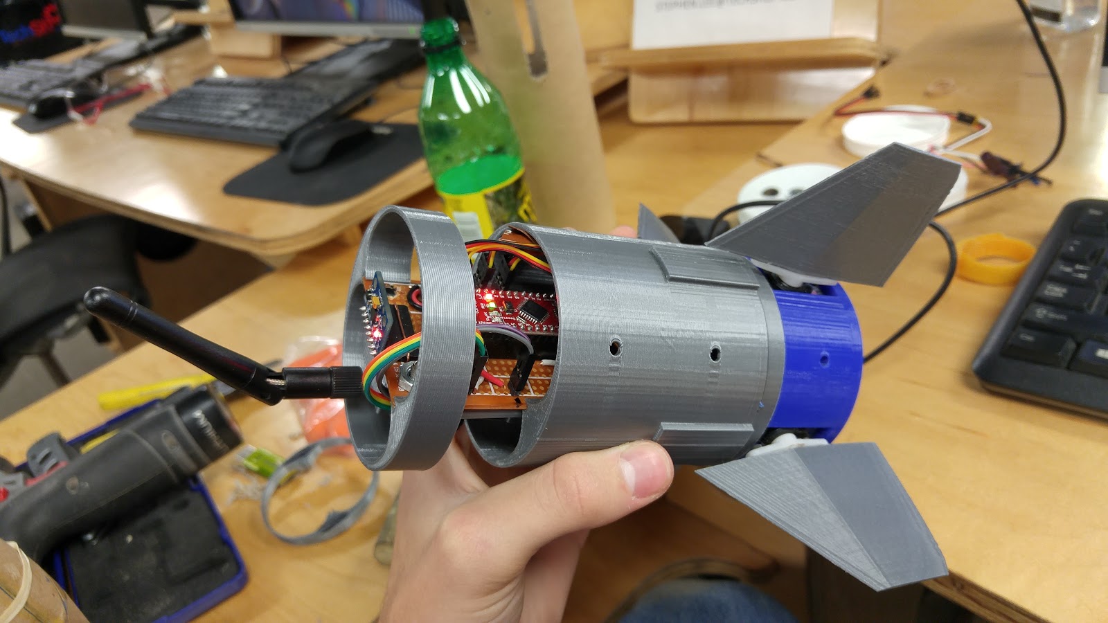
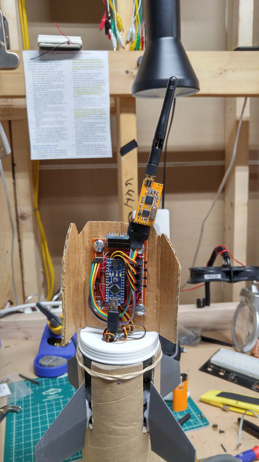
![]() The breadboard and connection board of the previous version were not only too hard to set up quickly but also very fragile and annoying to work with. I'd had enough so finally I went and built a nice shield that integrates almost everything while still keeping the Arduino removable so it can be used in other projects. V1 was a first attempt, all wires were red (bad idea) and shoddily laid out which caused a lot of headaches when it simply failed to work when powered up. Debugging when powered up showed the 5V rail hanging around 1.2V and not budging at all even when everything was disconnected. After a few hours of frustration my father walked by and offhandedly remarked to check the ground, much to my chagrin I found that I'd forgotten to connect the ground net to the ground rail which promptly fixed the problems (check for floating grounds). On the second revision the power and ground wires were in standard red and black while signals are in white (I ran out of wire colors okay?) in addition to being MUCH cleaner and better laid out. On the final revison, the IMU will be flipped around 180 degrees since this mount has it offset from the centerline by about 1/4in which may cause control reference issues resulting in the loss of launch vehicle.
The breadboard and connection board of the previous version were not only too hard to set up quickly but also very fragile and annoying to work with. I'd had enough so finally I went and built a nice shield that integrates almost everything while still keeping the Arduino removable so it can be used in other projects. V1 was a first attempt, all wires were red (bad idea) and shoddily laid out which caused a lot of headaches when it simply failed to work when powered up. Debugging when powered up showed the 5V rail hanging around 1.2V and not budging at all even when everything was disconnected. After a few hours of frustration my father walked by and offhandedly remarked to check the ground, much to my chagrin I found that I'd forgotten to connect the ground net to the ground rail which promptly fixed the problems (check for floating grounds). On the second revision the power and ground wires were in standard red and black while signals are in white (I ran out of wire colors okay?) in addition to being MUCH cleaner and better laid out. On the final revison, the IMU will be flipped around 180 degrees since this mount has it offset from the centerline by about 1/4in which may cause control reference issues resulting in the loss of launch vehicle.![]()
![]() Since I will be monitoring this launch from the ground during ascent I needed to get a telemetry solution figured out. Since I had a pair of APC220 wireless UART transceivers laying around after I was gifted them the year prior I decided to use those since they were not only on hand but had good nominal range (2Km LOS). After an initial prototype of a backpack in cardboard and hot glue, I designed and printed a proper backpack that has Velcro to hold down the module and a captive adapter for power and data lines. This assembly bolts onto the back of the control board with two diagonally placed holes as all 4 would interfere with my...not so great point to point soldering.
Since I will be monitoring this launch from the ground during ascent I needed to get a telemetry solution figured out. Since I had a pair of APC220 wireless UART transceivers laying around after I was gifted them the year prior I decided to use those since they were not only on hand but had good nominal range (2Km LOS). After an initial prototype of a backpack in cardboard and hot glue, I designed and printed a proper backpack that has Velcro to hold down the module and a captive adapter for power and data lines. This assembly bolts onto the back of the control board with two diagonally placed holes as all 4 would interfere with my...not so great point to point soldering. ![]() Powered up 90% completed model
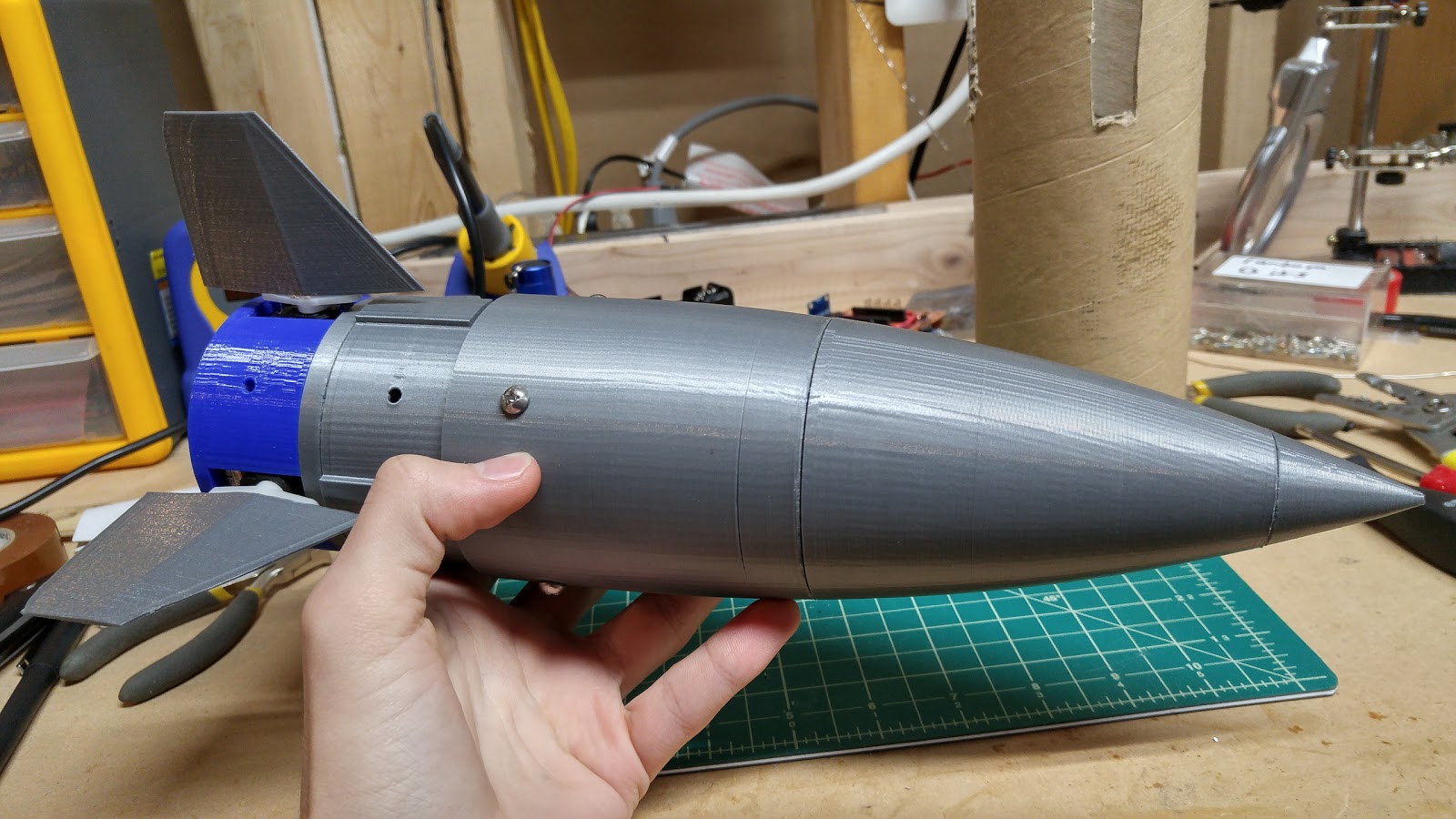
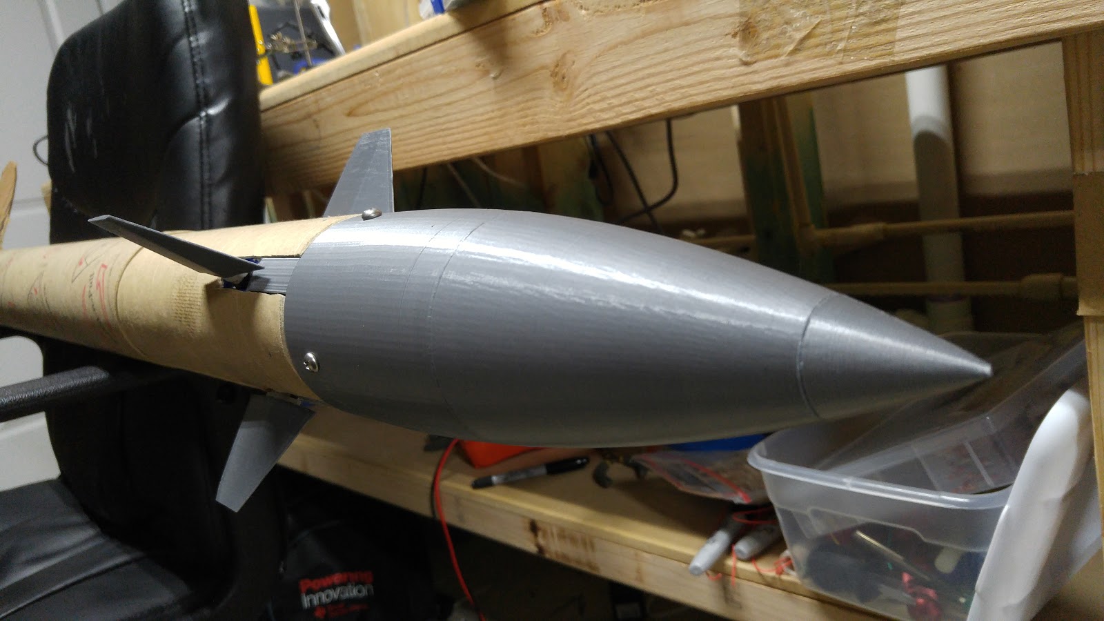
Powered up 90% completed model ![]() The nose cone was quite the interesting design challenge, the total height was 15 inches which surpassed the 6.1 inch maximum vertical print volume of the Makerbot Replicator 2s at TechShop. I decided to print the nose cone in 3 parts that bolted together for modularity and ease of printing. One of the biggest challenges in this was figuring out how to get the bolt interfaces designed on the curved surfaces of the nose cone interior while still being printable without support structure. In the end I opted for simple curved leadup flush connection plates which worked phenomenally with the minimal droop of Hatchbox filament (not sponsored, just freaking love that filament).
The nose cone was quite the interesting design challenge, the total height was 15 inches which surpassed the 6.1 inch maximum vertical print volume of the Makerbot Replicator 2s at TechShop. I decided to print the nose cone in 3 parts that bolted together for modularity and ease of printing. One of the biggest challenges in this was figuring out how to get the bolt interfaces designed on the curved surfaces of the nose cone interior while still being printable without support structure. In the end I opted for simple curved leadup flush connection plates which worked phenomenally with the minimal droop of Hatchbox filament (not sponsored, just freaking love that filament).![]()
![]() Lastly, an update that cannot be shown due to those pesky ITAR restrictons; code revisions! I've started a ground up rewrite of the code, this time with full Kalman filtration of the sensor values and PID to finally ditch the modified example code with shoddy division operators and no tuning ability. So far it's been a challenge as I am unsure as to whether the Kalman should go in front of or after the PID control, has stumped me since the rewrite was on the books. However, I did get some advice from internet friends so the Kalman will be feeding it's output into the PID. In addition to the code upgrade, I've been considering upgrading to a more powerful Arduino or just going ARM, maybe even use the MSP432 that TI sent over for the additional horsepower that will be needed to crunch all the numbers involved in the new code.
Lastly, an update that cannot be shown due to those pesky ITAR restrictons; code revisions! I've started a ground up rewrite of the code, this time with full Kalman filtration of the sensor values and PID to finally ditch the modified example code with shoddy division operators and no tuning ability. So far it's been a challenge as I am unsure as to whether the Kalman should go in front of or after the PID control, has stumped me since the rewrite was on the books. However, I did get some advice from internet friends so the Kalman will be feeding it's output into the PID. In addition to the code upgrade, I've been considering upgrading to a more powerful Arduino or just going ARM, maybe even use the MSP432 that TI sent over for the additional horsepower that will be needed to crunch all the numbers involved in the new code.On a funny note, the last day I was at TechShop for this month block, had packed everything up and found that the rocket was going to be too hard to carry around in parts. I left it assembled, slung it over my shoulder and walked out the door. Now you'd probably expect raised eyebrows considering it was in a government town but that is not the case on this particular day. It just so happened to coincide with a munitions expo, so while heading out I passed a crew wheeling out a SM3 missile mockup.
![]()
![]()
![]()
![]()
![]()
![]() Hacker for scale
Hacker for scale![]()
![]()
![]() 3 Years apart, it's come a LONG way
3 Years apart, it's come a LONG way![]() Bonus Crystal City late at night after a long day of work at TechShop
Bonus Crystal City late at night after a long day of work at TechShop -
A long overdue bug fix and testing update.
10/20/2015 at 18:47 • 1 commentThis system has been plagued with a pair of bugs that defied all logic; the Harlem Shake bug where the IMU spits random values out of nowhere even when perfectly still and the Iceman glitch where the whole system freezes up and shuts down. After mucking around with the code and a string of long nights trying to figure out what the heck was wrong with the system, I finally fixed the problem. The root cause is just inferrences at the moment, if anyone has a better theory I'd be glad to hear it. Simply changing the serial baudrate from 9600 to 115200 appears to have fixed the problems. Reading the serial logs led me to believe that the freezing glitch was caused by a FIFO (First In First Out) overflow due to the appearance of that message just before the system locked up. Initially, I had messed with the FIFO configuration to no avail before inferring that the data was coming in at a much higher rate than it was being output. My assumation is that the transcoding of the data was taking up too much processor power and causing it to get way out of whack. Googling around proved this to be the case and the fix was to increase the baudrate. After applying this fix, the system ran for 10 hours without any bugs or freezing at all, then I tested it 5 more times with resetting and the bugs did not reappear.
A few months ago I wrote a request on the member board at TechShop DC asking if anyone had ideas on how to get permission to use a runway for kinetic testing of a system, much to my surprise I got a response. None other than the owner of the Washington Executive Airport offered to let me use his 3000 foot runway for the testing. I am planning on heading up there sometime in November to check out the airport and start doing test operation planning and figuring out where to put cameras for video capture. This also is going to be time for the test rig to be built and I'll be needing to start fuselage integration immediately, or at least very soon. More updates as it comes!
-
Hackaday feature, project status
09/15/2015 at 01:14 • 0 commentsAs many of you have seen, I went to the DC Hackaday event and brought along the system to demonstrate and give a talk about. After fighting FTDIGate for a while, I eventually got the debug working and was able to present it without it giving me issues or the annoying "Harlem shake" bug. A recording of my talk is going to be at the bottom of this post where those who were not in attendance can watch it. At the moment, I am working on getting new servos and designing it into a test airframe for kinetic testing on a runway and/or a wind tunnel (If UMD will loan me some time on it). Later this week I'll be calling the local airport and the auxillary runway to see if they will let me drive a car with a rocket hung off the side down their runway at high speed (sounds crazy, is insane but hopefully will work with the power of "i'm doing a student project") More posts will be going up later this week to show the development.
Remember, past in-depth logs are on the blog.
-
General heads up
01/20/2015 at 16:06 • 0 commentsThought this page needed an update on the status of the project. It is NOT abandoned, just swamped in schoolwork. A more detailed update is coming later this week
-
Update 2
11/10/2014 at 23:20 • 0 comments//Back again with another update! Many apologies for the extended hiatus, school is quite hectic with it being my final year and the heavier workload of AP Physics and trying to maintain a relatively good GPA in addition to some other unrelated things going on that weighs rather heavily on my time, thanks for your understanding.
Back in the beginning of September I had started work on taking a prototype shield (these) and soldering the circuits on the back using standard hook up wire and converting it into a guidance shield for easier demonstration purposes and to minimize the rats nest of loose wires hanging out all over the place. This increased the durability of the entire system but hit a major hardware snag when it did not work as it did on the breadboard. The issue was it started moving the servos a single tiny skip then shutting the whole system down. What was happening is that the servos were drawing far too much current for the 5V pin and the Arduino shut down to protect itself as it thought it was short circuiting, not an I2C bus issue as I first surmised. I figured it out at last earlier this week, when I used an additional power supply for the servos (lots of power required to move 4 of them simultaneously). This fixed the biggest hardware problems I was having with a minimal amount of changes required to my circuitry (will need only an additional regulator) and no major changes to the code (will be moving the servo pins to PWM next revision). When you encounter an issue, first thing to check is for shorts, then to see if something else has gone wrong such as a misplaced connection or a solderblob jumped terminal that should not be connected. -
Update 1
11/10/2014 at 23:20 • 0 commentsI will be delayed in the development of the system on the code side due to the loss of my MPU-6050. The magic blue smoke of failure made a surprise appearance yesterday. I connected it to the 5V pin of the Arduino and suddenly wisps of smoke wafted past my screen as the power LED dimmed and powered off. I tested the temperature of the components and found the voltage regulator to be at fault. I did not over voltage it as it was rated to 5V. Likely the component was either faulty or it might have been a low quality wafer. The replacement components will be arriving in a few weeks (they have to get here from the opposite side of the planet) so until then I will be working on the physical structure of the drop test module for the test before the end of the year. Currently my objective is to secure a location from which to drop the unit from as so it can get up to the proper airspeed for the fins to come into play and control the fall of the unit. Initially I had called the local university as they have tall buildings which the town I live in does not (aside from the precinct which will not let me drop things off their roof). The administrator I talked to was extremely helpful and asked around as to wether or not I would be able to use their facilities. I was unable to use the facilities due to their insurance policies and the fact that the roof membranes are rather fragile, however he did give me several other places to ask which will hopefully allow me to test this system. Until the next post, Arsenio Dev signing off
-
Preliminary fin prints
08/20/2014 at 16:44 • 0 commentsPrinted the first fin today, it got messed up really bad, warping and bad layer stacking galore! the support structure wouldnt cleanly break off!
![]()
![]()
![]()
Printed vertically and the difference is night and day!
Also reprinted the baseplates at the proper size and now the servos are a snug press-fit and don't collide in the support structure
![]()
Arduino rocket stabilization system [UD: 7/14/17]
Arduino powered rocket stabilization system for mid to high power rockets that gets rid of the pitch over and subsequent downrange flight


 Initial test version showing issues with PID output (orange)
 The magical sight of a working PID plant in action.


 I also decided to invest a bit more into my content this year and bought myself a proper DSLR during the black friday sale and have been playing around with it. After a ton of research, the Nikon D3400 stood out above the rest and the black friday deal on the full starter set made it a no-brainer. Now the videos and pictures for the blog and youtube channel will get a dramatic increase in quality. Below are some high resolution (6000x4000) images, previously had just been shooting with my LG G4 which has a great camera but can't compete with the MUCH larger sensor and aperture of a full size camera.


![Basic system block diagram with in-progress notes [Blackbox project note censored for safety]](https://2.bp.blogspot.com/-we0Mu2rvEdU/V6yysIw2znI/AAAAAAAAE4M/AhE1K0zwfZcYhVw-kNRZd2U_1QhGHUykgCPcB/s1600/002.png)


 Hacker for scale
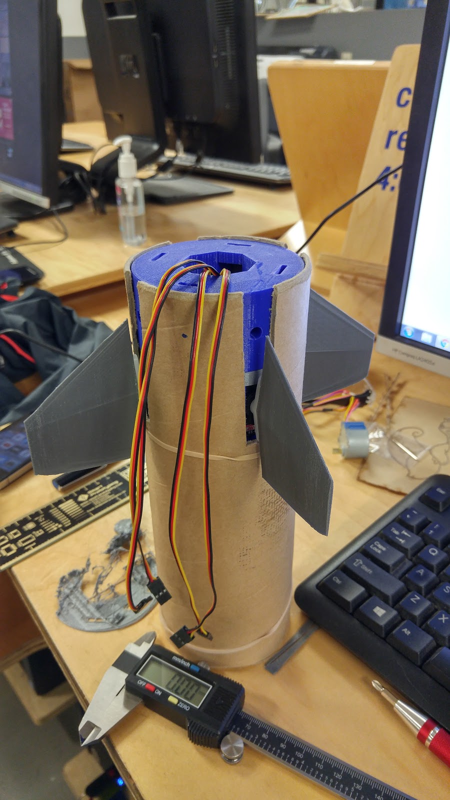
 3 Years apart, it's come a LONG way
 Bonus Crystal City late at night after a long day of work at TechShop


