 Andy Castille
I started by attempting to use serial communication, but ended up using infrared to emulate the remote.
The links above go to my original blog posts, which I have also copied as project updates below.
Adding WiFi to a 15-year-old LCD projector
Already have an account? Log in.
To make the experience fit your profile, pick a username and tell us what interests you.
I started by attempting to use serial communication, but ended up using infrared to emulate the remote.
The links above go to my original blog posts, which I have also copied as project updates below.
web_ui.html.txtWeb UI as a formatted HTML fileplain - 8.05 kB - 08/09/2020 at 03:19 |
|
|
src.cppCode flashed to the Particle Photon boardplain - 10.06 kB - 08/08/2020 at 21:06 |
|
By the end of the previous post, I had decided that the reliability of a direct serial line to the projector wasn’t worth the cost of a MAX232 chip over some IR diodes, so I ordered the latter. I anticipated the process of extracting the IR codes from the remote and replicating them would be difficult, lengthy, and finnicky, but it was actually pretty easy.
My final working build uses these components:
For recording the IR codes from the remote, I used a receiver diode connected to an Arduino Uno with the following configuration:
| Receiver Diode | Arduino |
|---|---|
| + Cathode | 5V out |
| Signal | Pin 11 |
| − Anode | GND |
Then I flashed the IRrecvDump example from Ken Shirriff’s IRremote library to the Arduino Uno, pointed my projector’s old remote at the receiver, and pressed every single button, noting the hex code output to the serial console. It also printed “Decoded NEC” each time, indicating Sanyo chose to use NEC’s IR protocol, which is important to know when sending these codes to the projector later.
I ended up with the following code table:
| Remote button | Code |
|---|---|
| Power | 0xCC0000FF |
| Computer input | 0xCC001CE3 |
| Video input | 0xCC00A05F |
| Menu | 0xCC0038C7 |
| Left arrow | 0xCC007887 |
| Right arrow | 0xCC00B847 |
| Up arrow | 0xCC0031CE |
| Down arrow | 0xCC00B14E |
| Select/OK/enter | 0xCC00F00F |
| Digital zoom up | 0xCC00807F |
| Digital zoom down | 0xCC0040BF |
| Page up | 0xCC009A65 |
| Page down | 0xCC005AA5 |
| Keystone | 0xCC00DA25 |
| No show | 0xCC00D12E |
| Auto PC adjust | 0xCC00916E |
| Power-off timer | 0xCC0051AE |
| Image settings | 0xCC0030CF |
| Freeze | 0xCC00C23D |
| Mute | 0xCC00D02F |
And any time I held a button, it sent 0xFFFFFFFF. I saw an “NEC repeat code” referenced in the IRremote documentation, so I’m assuming that’s what it is. I included it in my final project code, but it is never actually sent, and I have not needed it so far.
When I was done recording the codes, I assembled a second breadboard for “production” use where I had just a Particle Photon, an IR emitter diode, and a resistor between A5 on the board and the diode to protect the diode. I then strapped this to the side of my projector so the emitter sat in front of the projector’s IR receiver.
Speaking of project code, I have uploaded the full code I flashed to the Particle Photon (with the MQTT server and credentials emptied, of course) as a project file.
It hosts a web interface and API for manual control over the network, but it also connects to an MQTT server for control by home automation software.
It requires the following libraries:
For fun, I designed the web interface it hosts to look exactly like the original remote:
Hopefully, your browser has rendered the HTML document beautifully above. The HTML document behind this isn’t as pretty as the result, (especially when represented as a string in the C++ source code) but you can download it as a formatted HTML file from the project files if you wish.
Clicking a button on that preview will not do anything, but when hosted from the board,
it will make an HTTP POST request to the board that contains the form data key button
and a numeric value. The getCommand function parses this value and maps it to
an IR code for transmitting to the projector.
Sure, a web UI is fun, but it’s not very convenient. Navigating to the page in a browser isn’t as fast as picking up the remote off the table. This is where the MQTT functionality comes in.
In Home Assistant, which is connected to the same MQTT broker as the projector control, I created two scripts: one to turn the projector on by “pressing” the power button, and the other to turn it off by “pressing” the power button twice (once to open the “are you sure?” dialog, and again to confirm).
script:
  ...
  projector_on:
    alias: Projector on
    icon: mdi:projector
    mode: single
    sequence:
 - service:...
Read more »
But where to start? I had no idea how to use this port. Luckily, I wasn’t the first to try this. I found “Projector Controllers for Sanyo Projectors”, an old SourceForge project, that attempted to do the same thing. This told me that the service port was an 8-pin mini-DIN serial port. As for my specific model, I found several “serial command manuals” (such as this one for the Sanyo PLC-XU106) that detailed the serial protocol and commands. They were all similar enough (differing only in the number of commands available, which makes sense given the different models have different features) so I assumed the basic on, off, and input switching commands would work with my projector.
 Using this knowledge, I found and ordered a breakout connector (shown and linked above) that would let me use such a cable into with my microcontroller boards, and a serial cable to go between it and the projector’s service port.
My projector’s manual did provide a little bit of useful information: the service port pin numbering and assignment (shown below)
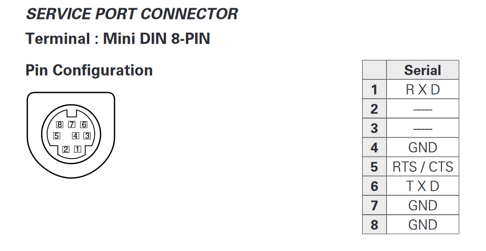
Combining this with the datasheet for the breakout connector from Mouser, I created this mapping table:
| Projector | Number | Color | Arduino |
|---|---|---|---|
| RXD | 1 | Brown | TX (3) |
| — | 2 | White | — |
| — | 3 | Black | — |
| GND | 4 | Blue | — |
| RTS/CTS | 5 | Green | ? |
| TXD | 6 | Yellow | RX (2) |
| GND | 7 | Orange | — |
| GND | 8 | Red | GND |
Despite the presence of an RTS/CTS line, the manual says that flow control is not needed.
Now I had everything I needed to communicate with the projector using an Arduino Uno I had laying around. I wrote the following sketch to be able to write my own data out and receive incoming data while sending the required CR between commands:
#include <SoftwareSerial.h>

SoftwareSerial projector(2, 3);

char buffer[64];
byte index = 0;

void setup() {
  Serial.begin(19200);
  while (!Serial);

  projector.begin(19200);
  while (!projector);

  Serial.write("Ready\n");
}

void loop() {
  // Projector -> PC
  if (projector.available()) {
    Serial.write("RX: ");

    while (projector.available()) {
      Serial.write(projector.read());
    }

    Serial.write('\n');
  }

  // PC -> Projector
  while (Serial.available()) {
    char c = Serial.read();

    if (c == '\r' || c == '\n') {
      // Send buffer to projector
      projector.write(buffer, index);
      projector.write(0x0D);

      // Echo buffer
      Serial.write("TX: ");
      Serial.write(buffer, index);
      Serial.write('\n');

      // Reset buffer
      index = 0;
    } else {
      // Add to buffer
      buffer[index++] = c;
    }
  }
}
But did it work? No. I sent many commands through the serial console and got left on read an equal number of times.
To figure out what was going on, I hooked up a logic analyzer to all of the lines and recorded sending messages from the Arduino and waiting for a response, as shown here: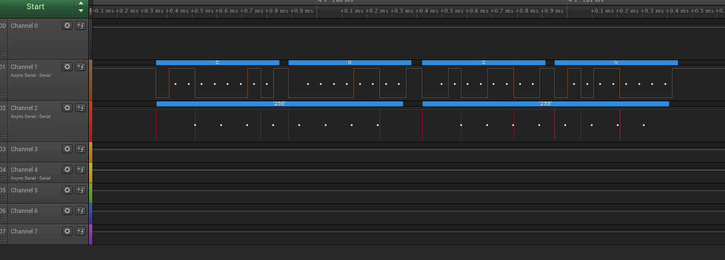 I’m not sure what the ‘255’ on the GND line was from, but I’m assuming it was just crosstalk due to the cheap breadboard I was using.
After another couple hours of trying different combinations of wires and serial data, I figured it must be the incorrect voltage. The Arduino was only communicating with 5 volts, but RS-232 could go much higher. If the projector was expecting 12 volts, it wouldn’t count 5 volts as a signal. Before sending higher voltages into my projector without knowing, I decided to email the person behind the Projector Controller project on SourceForge that I mentioned earlier. I figured it was a long shot that the email was still valid because it had been 10 years since the project was last active, but I was desperate.
I sent an email asking about what voltages were tested and working, and to my surprise, I got a response, and quickly! The relevant part:
Its been a while since I looked at this. In my circuit I used a max232 level converter chip, so I’m guessing its 12v. It should be reasonably safe to try this. In my other software project I would have used a usb to serial converter which also would likely be 12v.
Looks like I was right. Unfortunately, the level converter chips aren’t cheap, and I had already spent about $15 on this project, so I assumed I was...
Read more »The backstory: Many years ago, I bought an old Sanyo PLC-XU48 from Craigslist for $50. Since then, I’ve used it as a TV to watch videos and movies and play games. The resolution (1024x768) isn’t great by today’s standards, but at a distance it’s fine for my use.
The problem: Recently, the power button on the remote has decided to only work a tiny fraction of the time, which is really frustrating when trying to double-press it to turn off the projector.
First attempt at a solution: A new remote? Boring. Serial is much more exciting! I have some Particle Photon boards, which are Arduino-like microcontrollers with WiFi and I wanted to use one to communicate with the projector through its serial “SERVICE” port instead of using the remote. This would also let me integrate it with Home Assistant or write a web interface.