-
Arduino KISS interface
11/07/2021 at 19:29 • 0 comments![]()
Trying to avoid to reinvent the wheel, so I found some KISS sources:
- https://github.com/EnhancedRadioDevices/HamShield_KISS : C code, depends on AFSK
- https://github.com/markqvist/OpenModem : C code, depends on AFSK and on AX.25
- https://github.com/mobilinkd/tnc1/blob/master/mobilinkd-tnc1/ : C code, depends on BeRTOS and AFSK, adds non-standard escape codes for some reason. Using the ExitKiss-command instead might have been the preferable option.
- https://github.com/mobilinkd/NucleoTNC/tree/master/TNC and https://github.com/mobilinkd/tnc3-firmware/blob/master/TNC : real C++ code
A lot of time and effort has been put in these firmwares, but... For implementing a KISS interface, shouldn't the code be KISS as well? These source codes are not simple (relying on AFSK and/or AX.25) makes the class complicated and hard to port to other platforms or tool chains. The firmwares are not for the stupid either. The Mobilinkd C++ code may be beautifully written, but it's hard to read for novice C++ programmers.
So I'll need to write my own code based on the PacketSerial and HamShield_KISS libraries while adhering as much as possible to the KISS-"standard".
Android
As mentioned elsewhere, instead of implementing all functionality in a single device, I'll offload functionality to an Android device. These apps are already there, so why not use them? Why would I decode Codec2 samples in the ESP32 when there's already an Android app that can do that for me?
The only thing needed is a KISS-TNC interface and a Bluetooth serial port to talk to these Android apps. This is not so hard to do.
Codec2 Talkie
I have tested my KISS-TNC code with the sh123 android app to send and receive Codec2 speech samples. Codec2 samples sent by the ESP32 were correctly decoded and output on the Android app. I've also off-line decoded Codec2 samples that the ESP32 received from the Android app.
Aprsdroid
Sending voice with Codec2 Talkie is one thing, but it would be nice to have a messenger application with the added bonus of sharing location info. That is what Aprsdroid can do for us.
I'll mention Ripple Messenger (and LoRa Qwerty Messenger) here as an alternative, but that application looks like a single person project.
APRS uses only a subset of the AX.25-framework. And Aprsdroid in its turn only uses a subset of the APRS-protocol. So we can suffice by only implementing a very limited set of the AX.25-framework.
Moreover, the data we receive over the KISS-interface doesn't carry flags, has no checksum and isn't bit-stuffed either. This also saves us a considerable amount of work.Unfortunately, the APRS-protocol is a real mess. It seems like the standard has been written after the fact, trying to match the standard to different applications already seeing field use.
![]()
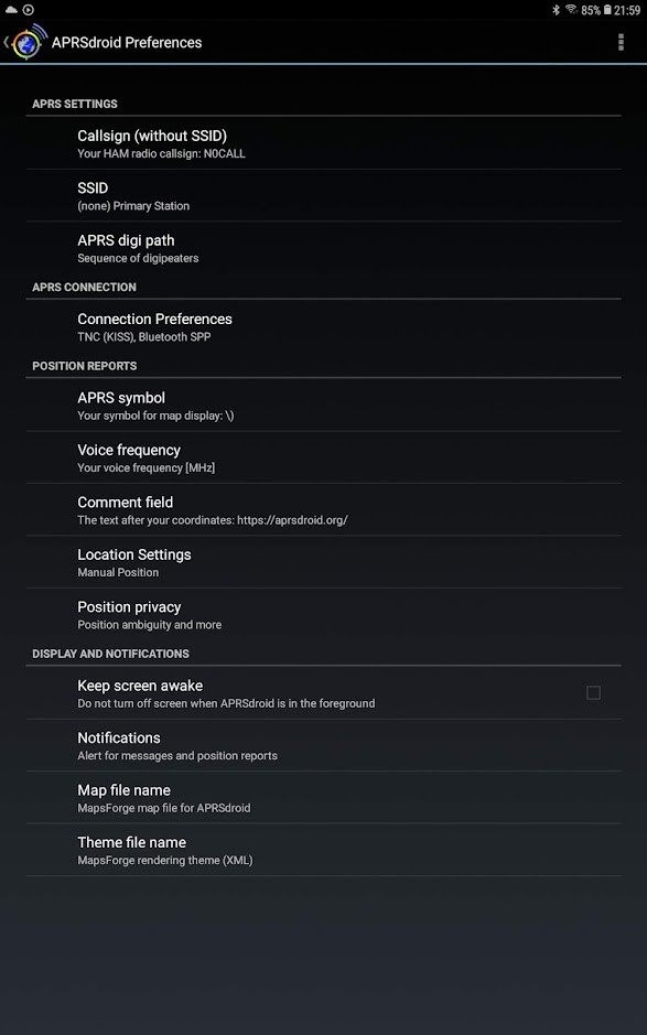
Settings for Aprsdroid to communicate with our TNC. (cdn.hackaday.io/images/5671441640889476886.jpg) Location reports
AX.25-frame, received as Data Frame by our KISS-TNC :
0x82 0xa0 0x88 0xa4 0x62 0x6c 0xe0 0x9c 0x60 0x86 0x82 0x98 0x98 0x61 0x03 0xf0 0x3d 0x30 0x31 0x30 0x30 0x2e 0x30 0x30 0x4e 0x5c 0x30 0x30 0x32 0x30 0x30 0x2e 0x30 0x30 0x45 0x29 0x20 0x68 0x74 0x74 0x70 0x73 0x3a 0x2f 0x2f 0x61 0x70 0x72 0x73 0x64 0x72 0x6f 0x69 0x64 0x2e 0x6f 0x72 0x67 0x2f
Decoded by AX.25 Frame Generator :
Source & SSID: N0CALL-0
Destination & SSID: APDR16-0
PID : 0xF0 (no layer3 protocol)
CONTROL : 0x03 (UI Frame)
Payload: =0100.00N\00200.00E) https://aprsdroid.org/
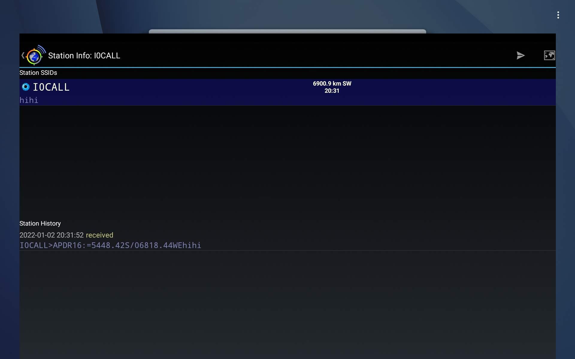
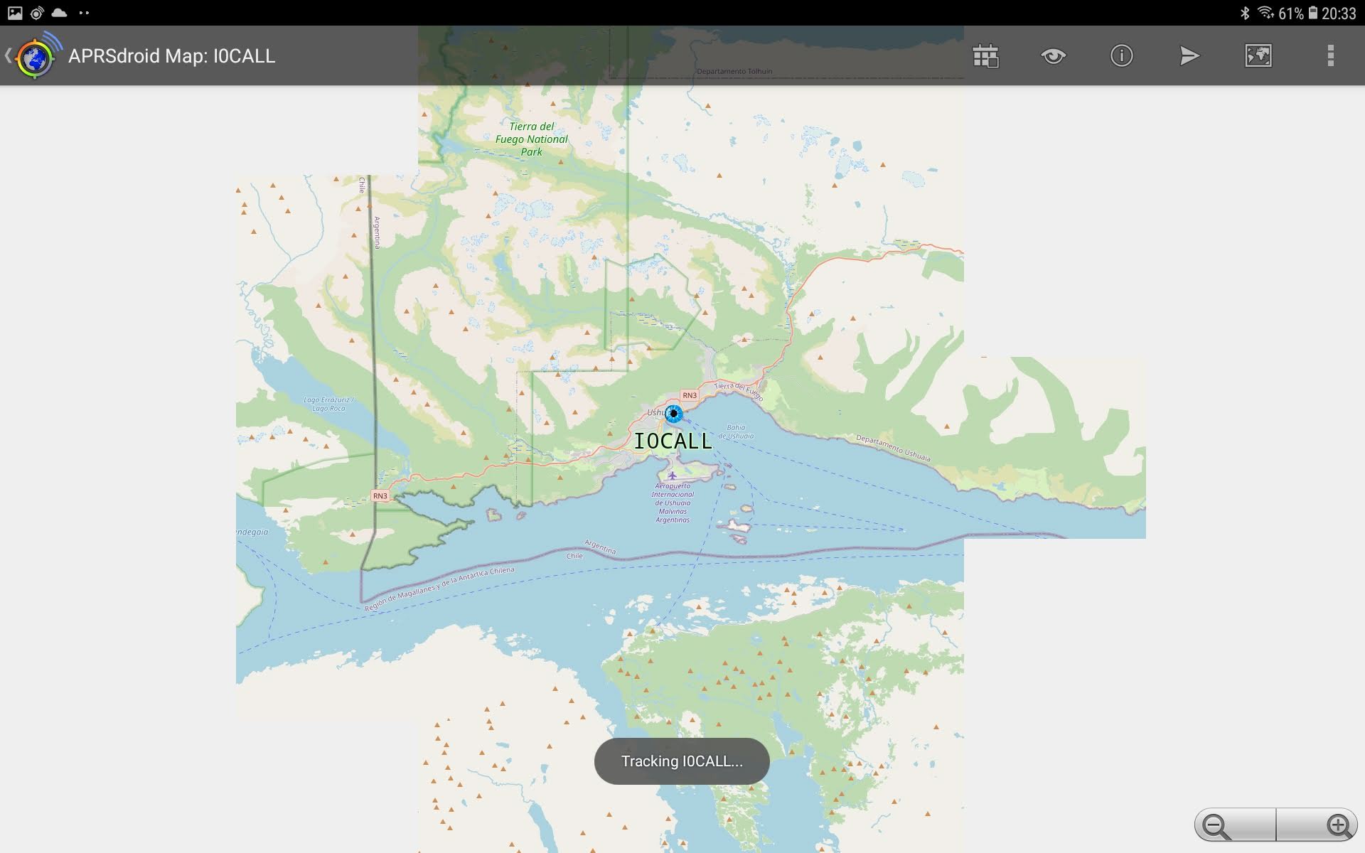
We can also send our own location reports to Aprsdroid:
![]()
cdn.hackaday.io/images/4244511641152187114.jpg ![cdn.hackaday.io/images/5451181641152204611.jpg cdn.hackaday.io/images/5451181641152204611.jpg]()
Fooling Aprsdroid by letting it know that we're in Ushuaia.(cdn.hackaday.io/images/5451181641152204611.jpg) Text message
More info can be found in the APRS-specification, chapter 14. Aprsdroid expects messages to be acknowledged, hence the '{' followed by a number at the end of the message.
AX.25-frame, received as Data Frame by our KISS-TNC :
0x82 0xa0 0x88 0xa4 0x62 0x6c 0xe0 0x9c 0x60 0x86 0x82 0x98 0x98 0x61 0x03 0xf0 0x3a 0x4e 0x31 0x43 0x41 0x4c 0x4c 0x20 0x20 0x20 0x3a 0x48 0x65 0x6c 0x6c 0x6f 0x20 0x77 0x6f 0x72 0x6c 0x64 0x7b 0x35
Decoded by AX.25 Frame Generator :
Source & SSID: N0CALL-0
Destination & SSID: APDR16-0
PID : 0xF0 (no layer3 protocol)
CONTROL : 0x03 (UI Frame)
Payload: :N1CALL   :Hello world{5
AX.25 References
- AX.25 Frame Generator : the KISS data frames received by our KISS-TNC can be pasted into the AX.25-Text frame on that web page to decode them.
- AX.25 frame = Address + Control + Info fields from HDLC standard, before bit-stuffing.
- HDLC frame = AX.25 frame with flags, FCS (=checksum) and the bit-stuffing.
- RadioLib : only TX, no RX of AX.25
- LibAPRS : APRS-packet library : decoding and encoding of AX.25, APRS encoding only
- APRS-Specification 1.0.1
-
Security
07/25/2021 at 09:49 • 0 commentsThe advantage of using digital communication over analog is that it's much easier to implement decent security measures. Security deals with the following properties of the information:
- secrecy or confidentiality
- authentication
- non-repudiation
- integrity control
We won't reinvent the warm water here. We'll see what TLS1.3 and SSH have to offer us.
Key exchange
TLS leaves many options here, some of which are interesting to us: PSK and ECDHE and a combination of the two. In pre-shared key (PSK) mode, a pre-shared secret is established prior to key-exchange. This can be done using an out-of-band secure channel : serial cable, NFC, ... The problem with this approach is that it doesn't scale well. The pre-shared secret should be unique for each combination of two devices. If you have 20 devices, you'll end up generating and distributing 20!/(2!*18!) = 190 unique pre-shared secrets.
ECDHE (Elliptic Curve Diffie Hellman with Ephemeral keys) is easier to manage. Each device in the group could be uploaded with a list of "certificates". This list could be store on an SD-card in the device. The list would be the same for all devices in the pool and it doesn't even need to be secret. WiFi could be used to upload the list to the devices.
Message 1 : Client to server
TLS1.3 as well as SSH start with the client that creates an ephemeral key pair. It then sends a random number (to prevent replay-attacks) and the ephemeral public key to the server.
The ephemeral key pair is only used for key exchange. Its lifetime is very short.
SSH
In SSH this actually takes two different messages.
- Random number = cookie, 16bytes long
- Ephemeral public key = e (in SSH_MSG_KEXDH_INIT message)
TLS1.3
ClientHello message
- Random : client_nonce = 32bytes
- Extension : key_share : client's ephemeral public key
Message 2 : Server to Client
The server creates an ephemeral key pair as well. For both protocols, the server's first message contains about the same arguments as the client's first message. The server then adds additional data.
SSH
- Random number = cookie, 16bytes long
- Ephemeral public key = f (in SSH_MSG_KEXDH_REPLY message)
Additional data:
- the server's static public key K_S
- signature: signing the hash of all known key exchange data up to now and signing it with K_S.
TLS1.3
ServerHello message:
- Random : server_nonce = 32 bytes
- Extension: key_share : server's ephemeral public key
Additional data: EncryptedExtension, encrypted with keys derived from handshake secret.
- Certificate
- CertificateVerify : provides authentication.
- Finished : provides key confirmation and binds the authenticated party to the used key.
Mutual authentication
As shown above, the key exchange only provides server authentication. The server has no way of telling who the client really is. Implementation of mutual authentication in TLS1.3, simply requires an extra message, with the client sending similar EncryptedExtension data.
Mutual authentication in SSH requires the SSH authentication protocol (RFC4252), which is a different message flow. In short, the client sends its public key and attaches a signature to prove possession of the private key.
Implementation
As the Arduino tool chain for ESP32 already includes libsodium, we'll use that. Monocypher can't be used with ESP32 because of linker conflicts with the libsodium library.
-
Housing
07/18/2021 at 20:25 • 0 commentsAs this project doesn't have a real use case yet, there's no requirement about the housing.
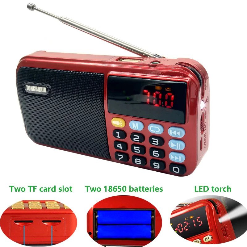
RadioThe original idea was to build the electronics in a Tongboxin C803 radio.
![]()
Unfortunately, there's very little room for electronics. The left side of the housing is taken up by the speaker. The bottom side is taken up by the 18650-cells.
The LED-segment display is soldered onto the PCB and needs to be de-soldered for taking the electronics from the housing.
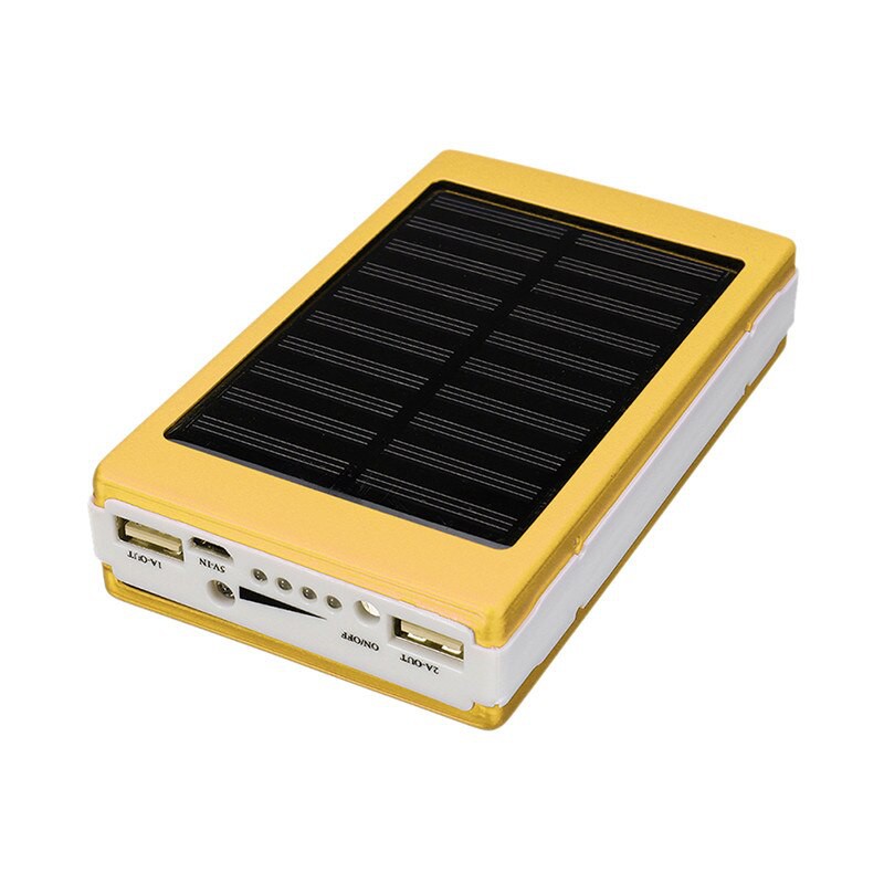
Power bankAnother option is to use a power bank housing. These are fairly cheap, already contain room for some 18650 cells. The solar panel is an extra, but probably won't be of much use. The LED-panel on the back might be replaced by some TFT-panel or LCD-panel. It's transparent anyway.
One of the things that would put me down is the probably low build quality. There are no screws to hold it all together.
![]()
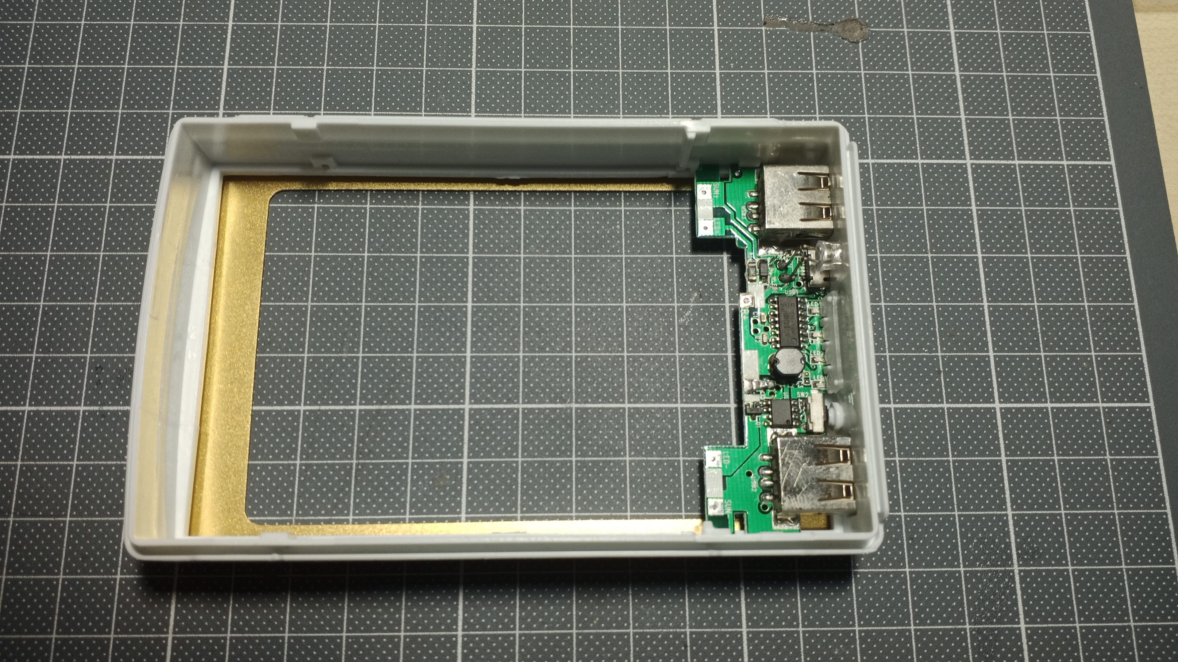
Well the housing has finally arrived. It's indeed low build quality. The housing is held together by four miniature screws on either side of the housing. There's a multitude of issues with this housing, but the main one is that it's not easily possible to mount connectors on the sides (SMA, audio jacks). There's also no means of fixing the 18650 cells. You're supposed to weld cells together. The housing is too low to use an 18650 battery clip.
![]()
The charging PCB is mounted fix, but there are no provisions to fix mount anything else. Extruded aluminium housing
YGKT on AliExpress sells extruded Al housings for a reasonable price. The metal housing will also serve as a ground plane for the monopole antenna.
I expect to need about 6000mm² PCB area. Three options remain:
- https://www.aliexpress.com/item/32802694790.html : 88x38x100mm, €8.2
- https://www.aliexpress.com/item/32764144816.html : 88x38x100mm, €6.97
- https://www.aliexpress.com/item/32764024806.html : 63x37x95mm, €5.5
-
Data link layer
04/22/2021 at 18:08 • 3 commentsPacketing
Packet interval
Codec2 1200bps has been selected, it needs to be fed 6 bytes every 40ms.
dPMR uses packets that are (Header (80ms) + 4* super frame(320ms) + end (20ms)) = 1.38s long! Using such long packets has the advantage that the overhead is relatively small for the payload. This also implies that the FIFO is refilled as the transmission is ongoing.
SCIP-210, Revision 3.6 §2.1.3 : Transport framing : All frames are split up in 20 byte frames, of which 13 bytes are data.
Packet size
The raw data rate of Codec2 is 1200baud. If consider that raw data will only make up 25% of the total packet interval, then we'lll need to send at least at 4800baud. The remainder of the packet interval goes up on:
- inter-packet dead time
- intra packet overhead for data link layer : preamble, sync word, CRC, ...
- intra packet overhead for transport layer (security)
If we want to adhere more or less to dPMR, we'll want to use 6.25kHz channels. 4800baud FSK needs more than 6.25kHz bandwidth, so we'll need more bits/symbol : 4(G)FSK.
This only leaves the SI4463 and AX5043 as options.
For the 1200bps, FSK and OOK are still options:
- SX1278 : FSK : 2.4kbps BR, 4.8kHz freq.dev., 7.8kHz Rx BW.
- SX1278 : OOK : 3.0kbps, 5.2kHz Rx BW.
Is there a suitable library for the SI4463?
- RadioHead library can send 4FSK data (with a suitable config file), but can't receive it.
- The #NPR New Packet Radio project is 2FSK as well as 4FSK, but it might be difficult to strip the radio code from the application. The interfacing to the SI4463 is very different from other sources. The application code seems very much interweaved with the interface to the radio.
- Zak Kemble's library was the first one I got working with 4GFSK. But it's interrupt based and many functions don't yield a return code.
- The official SiLabs WDS3 tool can create an example project. Unfortunately the header files are nearly unusable. A header file with commands is generated, which is about 3800(!) line long. Then there's also the header file listing the properties. That one is 5800(!) lines long. I spend more time finding the right "define" statement than it would have taken me to write the statement myself based on the HTML-documentation.
- The Arduino-LoRa library interface can be used as a template. It inherits from the Stream class, which will make it easier to interface it to other libraries such as PacketIO.
So I decided to merge Zak's code and the official WDS3 code into my favorite radio library : RadioLib.
Now with the library working (based on Zak Kemble's code), I noticed that sending the 10byte packes from Zak Kemble's example takes 57ms. That's measured from the end of the 0x31 START_TX command to the falling edge of IRQ that signals a PACKET_SENT. For 1200bps, we need to send 6 bytes every 40ms. If we can't get the TX-time down, we'll have to group codec2 frames in a single wireless packet. Sending 6 bytes takes 51ms (as verified with the logic analyser: time between end of START_TX and falling PACKET_SENT IRQ). This matches with the theoretical limit: 4 bytes in 6ms = 32 bit/6ms = 5.3kbps. The radio is configured for 2.4ksymbols/s (=4.8kbps for 4GFSK).
![]()
SI446x potential packet structure The following settings are used in Zak Kemble's library:
- Preamble : 8 bytes (sine wave) : 2.4kbps encoded, not 4.8kbps as the rest of the packet.
- Sync word : 2 bytes
- Field 1 : 1 byte (length of the packet)
- CRC-Field 1 : 2 bytes
- Field 2 : data bytes (e.g. 6 bytes)
- CRC-Field 2 : 2 bytes
So we have 15 bytes overhead for our packet. With respect to time, we even have 23 bytes overhead, because the preamble is sent out at half the bit rate. So the total packet time = (23 + N) * 8 / 4800 [s], where N is the number of data bytes.
![]()
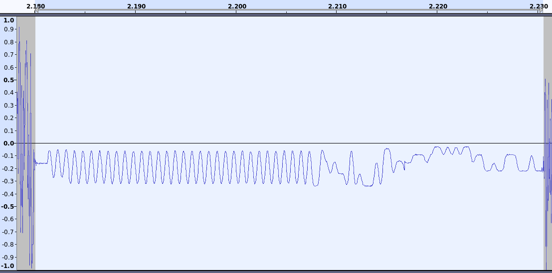
Recording taken with RSP1A and CubicSDR opened in Audacity. The selected length in the image is 51ms. It takes 48.3ms to send a packet with 6 data bytes. Codec2_1200 generates 6 bytes every 40ms. So Codec2 generates the packets faster than they are transmitted.
The following condition must be met:
23 = OH = overhead = the number of bytes that are sent, but are not Codec2 data. This includes preamble, sync, encryption, ...
Which can be simplified and generalized to:
N = number of data bytes, OH = number of equivalent bytes in overhead The upper communication layers will generate overhead as well. Authenticated encryption adds 20 bytes to the packet. Let's provision another 20 bytes for the higher OSI-layers.
So a number of data bytes should be at least N ≥ (23+40)/3 = 21. N must be a multiple of six, because of CODEC2_1200. So N becomes 24.
- N = 4 CODEC2_1200 frames per SI4463-packet = 4 * 6 bytes = 24 bytes
- OH = 23 + 20 + 20 = 63
- 23 bytes SI4463 data link layer (preamble, sync, CRC, etc.)
- 20 bytes of security data per packet (data secrecy + integrity)
- 20 bytes provisioned overhead
- Check 1: max. packet size : 15 + 24 + 20 + 20 = 79 bytes, which is smaller than the maximum capacity of 129 bytes of the SI4463. This however, involves stitching the two internal FIFO's of the SI4463 together. By default maximum packet size is only 64 bytes.
- Set property GLOBAL_CONFIG (group 0, index 3), field FIFO_MODE.
- Use FIFO_INFO command to make the change take effect.
- Each SI4463 packet contains 4 codec2_1200 frames, so 4 * 40 ms of audio = 160ms audio. The SI4463 sends one packet per 160ms.
- Check 2: total transmission time per packet = (23+40+24)*8/4800 = 145ms, which is smaller than 160ms.
- Speech total latency will be about 200ms, which is (not) acceptable. The acceptable delay for a normal conversation is 150ms. (FYI: the acceptable delay for your own echo must be below 50ms).
The downside of adding more data bytes in a packet is that the latency will increase. We have to find an optimum.
![]()
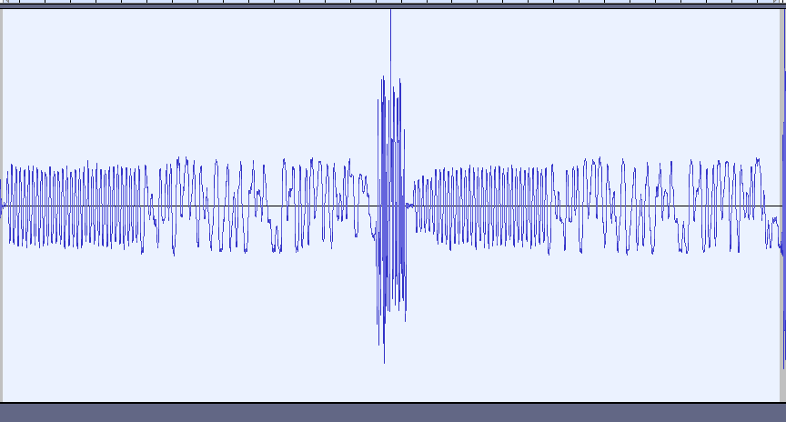
Two frames with 20 bytes of user data, separated by 7ms of noise (the high amplitude in the middle). See how much time goes into the transmission of the preamble at the start of every frame. -
Audio line level
01/24/2021 at 19:35 • 0 commentsCodec2 expects nominal signal levels to be able to decode data. So for testing how the codec2 encodes our packets, the PC will generate speech audio on its line-out (what voltage level to use here?), which is connected to the left line-in of the SGTL5000 audio codec, which will convert the audio voltage levels to 16bit PCM signed samples.
Maximum audio output voltage level
As a laptop only has a headpone output, no line out, I used an external sound device. The cheapest possible USB-audio card has been use here. It only costs €2.
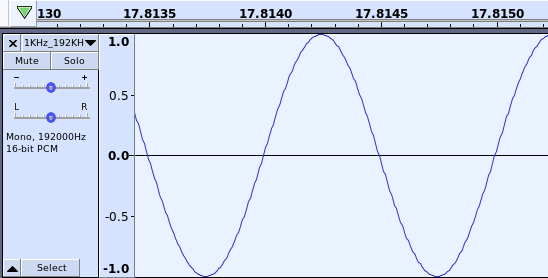
To find the maximum amplitude it can deliver, we download a 1kHz sine wave 0dB file (maximum amplitude). The values of the audio samples vary from -1 to +1.
![https://cdn.hackaday.io/images/7886221611515142020.png https://cdn.hackaday.io/images/7886221611515142020.png]()
1kHz 0dB wave file in Audacity Play it and set your computer sound volume to maximum. Then measure the amplitude. If the wave form starts clipping, then there's a problem in your audio system.
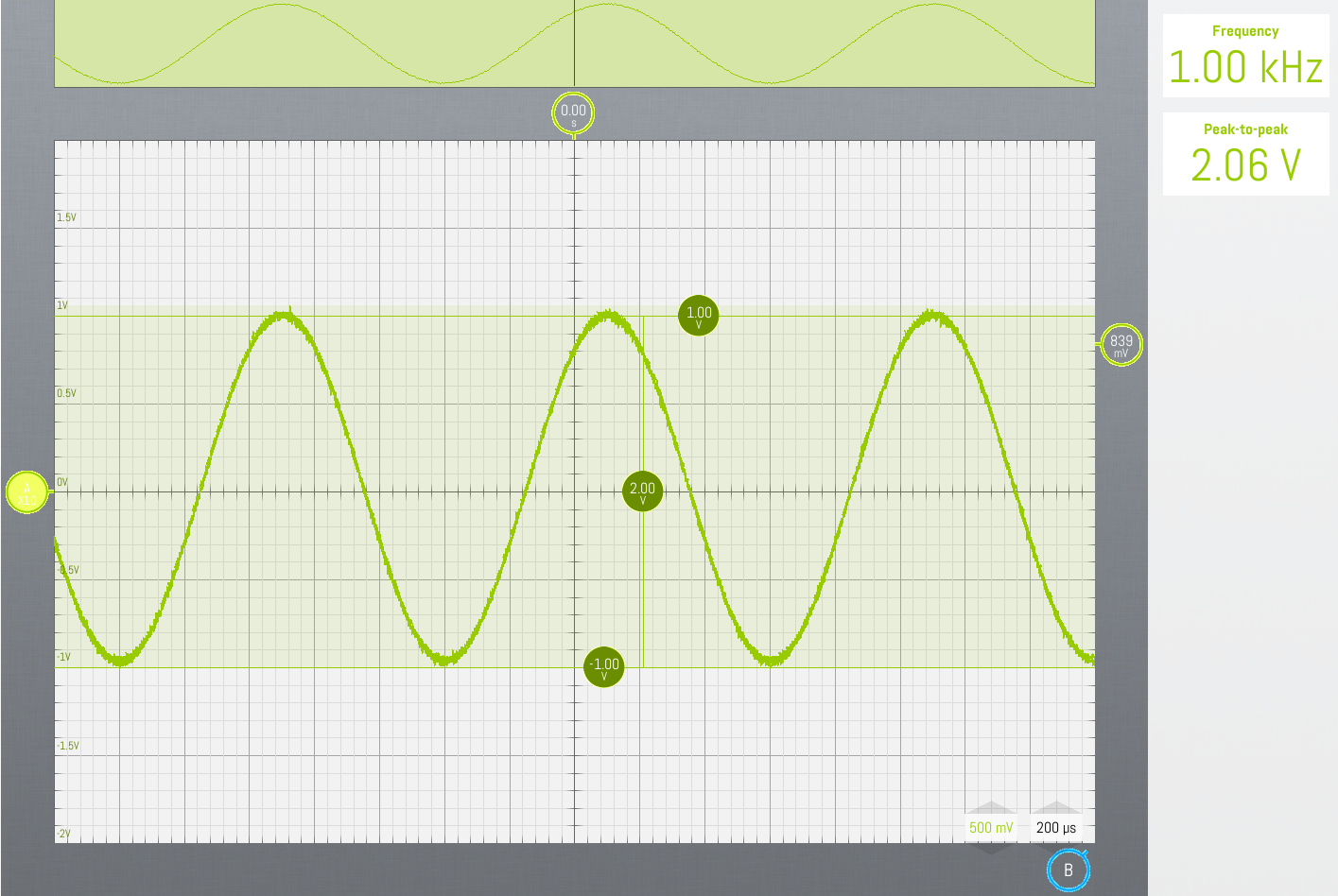
![https://cdn.hackaday.io/images/1174651611515177608.png]()
USB Soundcard at maximum amplitude, oscilloscope snapshot The unloaded headphone output of the Lenovo L580 Thinkpad even goes up to 1.68Vp (=3.32Vpp). Remark that the SGTL5000 only accepts up to 2.83Vpp (=1Vrms) line-in voltage levels.
Ok, so now we know that different audio sources have different maximum voltage settings.
Nominal signal level
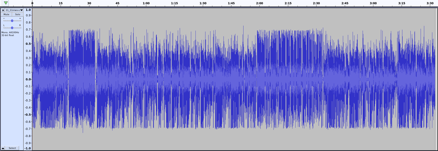
Maximum signal level is -1 to +1, but what should we use as nominal signal level? Let's download a speech sample from a news report, that one should be set correctly.
![https://cdn.hackaday.io/images/6552031611516446781.png]()
Audacity view from news report, signal level limited from -0.7 to +0.7. SGTL5000 audio codec
The analog gain stage before the ADC (controlled by the CHIP_ANA_ADC_CTRL register) of the SGTL5000 will need to be adjusted so that when a 0dB sine wave is played at maximum amplitude from the USB-sound card, it will result in 16bit samples that are also maximum amplitude.
Let's take a 100Hz sine wave, 0dB so that we have at least 80 samples per cycle. Remember we're using 8kHz sampling frequency because that's a codec2 requirement. Of course we might sample at higher frequencies, but then the ESP32 would have to down sample again.
The I2S samples could be printed to the Arduino serial plotter to get an idea of the amplitude.
-
ESP32 with SGTL5000
01/03/2021 at 14:36 • 0 commentsHardware
The SGTL5000 uses a virtual ground for the audio outputs. This likely makes it unsuitable for use in smartphone headsets in which the ground of the microphone is shared with the audio output. To be tested.
Generating I2S
The annoying thing about the Adafruit audio adapter is that it's not fully open source. These are the supply voltages:
- VDDD = 1.8V
- VDDIO = 3.3V (powers line out)
- VDDA = 3.3V (powers the headphone)
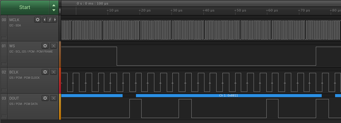
![https://cdn.hackaday.io/images/6563761610045017903.png https://cdn.hackaday.io/images/6563761610045017903.png]()
I2S standard format : data is one bit delayed with respect to WS edges. On the SGTL5000 datasheet, this is the one bit delay on I2S format with respect to the left-justified format on Figure 10. I2S Port Supported Formats. This seems to be normal I2S behavior.
The delay could be removed by setting the i2s_comm_format_t in the ESP32 to 0, but I'll just leave it to the standard setting.
The SGTL5000 considers the 16bit data as signed format. It's analog output is inverted, which actually doesn't matter much for audio. Voutmax corresponds to 0x8000 = -32768, while Voutmin corresponds to 0x7FFF = 32767).
The sample code to generate a 200Hz sine wave on the left channel of line-out and headphone can be found here.
References
-
References
09/16/2020 at 19:43 • 0 commentsProjects using the SI4463
- Little Free Radio: various data rates (and likely also packet lengths)
- SPACE-HAUC Ground Station UHF and their linux driver
- Eleph
Commercial products
Kiwi-tec LAP-E01
- Works in 920.6 ~ 928MHz band, +13dBm, Japanese TELEC certification.
- Uses Speex codec, which as demonstrated below (doesn't perform as well as Codec2 on low bit rates:
- 125kHz bandwidth LoRa
- Internal antenna : -0.4dBi
Prior art
nRF24 based
- Long Range Arduino Based Walkie Talkie using nRF24L01 : many similar projects, all using the RF24Audio library.
RFM12 based
- Walkie Talkie Duino using RFM12B "open source" (only to the Kickstarter backers).
RFM22 based
Analog FM based
- DRA818V analog FM module (lots of harmonics, will need a license to operate)
- Auctus A1846S : HamShield (by Casey Halverson), also available in Mini version.
- HamShield on Tindie
- Kickstarter
- Hackaday.io
- Instructables
- Github
- InductiveTwig
Comparable projects
KISS modem interface
LoRa
HamShield LoRa (by Casey Halverson)
STM32
- https://www.digikey.com/en/maker/search-results?&k=getting%20started%20with%20stm32
- NucleoTNC
- https://github.com/x893/Codec2WalkieTalkie
- 1024kHz FIR filter for sampling audio downto 4kHz
- QMESH
- Uses libcorrect as FEC library
ESP32
-
Hardware choices
09/15/2020 at 18:09 • 0 commentsPlatform
Flash size requirements
The codec2 library needs about 87KB, while the RadioLib needs about 10KB. Then, there's also the base Arduino libraries. And we still need to add our own code. To be on the safe side, a device with at least 256KB of flash will be needed.
ESP32
Test application built, based on Arduino codec2 library, but it crashed. This has been solved with esp32-codec2.
Some presumably also got it to work before I did, but they are unwilling to share their source code:
STM32STM32F4Discovery
- 168MHz
- lora-codec2
- STM32F407G-DISC1 (< €19)
- analog IO already on board
- supported by PlatformIO
- using exotic audio DAC
- rather large (66x97mm), might make integration more difficult.
Rowetel/Dragino Tech SM1000
- Github
- Implements codec2 on a STM32F405 (custom board design)
- audio : analog IO directly from STM32
NUCLEO-L432KC
Runs only on 80MHz, might be an option to shrink size.
More info on STM32 development
nRF5264MHz
github : Implements codec2 on a Adafruit Feather nRF52 Bluefruit LE.
Codec2 has been modified so that it can be built using Arduino framework. I doubt this implementation is working correctly.
- Adafruit ItsyBitsy nRF52840 Express - Bluetooth LE (Mouser & Digikey):
- small & cheap (€15), breadboard & IC-socket compatible
- support for Circuitpython & PlatformIO
- debug connection, but no integrated debugger
- as always from Adafruit : well documented
- Application to demonstrate PWM audio functionality on nRF52
Audio IO
I²S
On ESP32, using I²S is definitely advantageous because it can use DMA, which off-loads the reading and writing audio data from the processor.
As we're only processing low quality 8kHz speech here, a high-end audio codec like the SGTL5000 is not necessary, but it might be a good choice after all:
- open source support (pjrc)
- I²S sink & source in a single device.
- High quality audio might be useful for other projects and designs.
- Extra features:
- Input: Programmable MIC gain, Auto input volume control
- Output: 98dB SNR output, digital volume
- Development board price is acceptable.
A cheaper alternative is the Waveshare WM8960 Audio HAT (technical info).
PWM-DAC & ADC
The SM1000 and NucleoTNC contain the analog circuitry we need.
Adafruit Voice Changer also features some form of audio pass-through
-
Physical layer : wireless communication
08/26/2020 at 19:25 • 0 commentsTheory
Channel capacity
Shannon-Hartley law:
where C is channel capacity [bps], B is bandwidth [Hz] and S/N is signal/noise ratio.
Example: dPMR (C = 4800bps, B=6250Hz). So S/N must be at least 0.70.
Number of bits/symbol needed
Nyquist's Theorem :
Example: dPMR (C = 4800bps, B=6250Hz). So N is 1.3bits/symbol.
Noise floor
–174 dBm is the thermal noise floor at room temperature in a 1-Hz bandwidth.
e.g. for 10kHz bandwidth, the noise floor is -134dBm.
(see Long-range RF communication: Why narrowband is the de facto standard, Texas Instruments)
Legal limitations
We can only make use of unlicensed bands. Some bands only allow pre-certified equipment and fixed antennas. Here are some options for unlicensed spectrum. I left out the <100mW options and constrained myself to the sub-1GHz options. If you're looking for a DIY-solution for 2.4GHz, have a look at the nRF24Audio library.
27MHz
- Citizen band : 12W, SSB, 10kHz channels, 26.690MHz to 27.410MHz, some channels excluded
- Packet radio Germany : 27.235 MHz and 27.245 MHz
- Packet radio Netherlands: 27.235 MHz and 27.395(wikipedia)/27.405 MHz
- Packet radio Belgium : forbidden
- SRD : 100mW, 5 10kHz wide channels around 27MHz, <0.1% duty cycle
169MHz
- SRD : 0.5W, 169.4MHz to 169.475MHz, 50kHz channels, <1% duty cycle : BIPT B01-10
446MHz
- PMR446 : 0.5W, ,6.25kHz or 12.5kHz, 446MHz to 446.2MHz
- dPMR446 aka dPMR tier 1, ETSI TS 102 490 & ETSI TS 102 587.
823-832MHz
- Intercom : 100mW, BW<200kHz
865-868MHz & 874-874.4MHz & 917.3-918.9MHz
- SRD : 0.5W, BW<200kHz, divided into 4 allowable sub bands, <2.5% duty cycle
869.4-869.65MHz
- SRD860 : 0.5W, BW<250kHz, <10% duty cycle
Side note
Polite spectrum access = listen before transmit (LBT) and adaptive frequency agility (AFA).
As contradictory as it might seem, LBT+AFA is no benefit over 10% duty cycle. It restricts the system to 100s per hour per 200kHz bandwidth (=2.8% duty cycle), a maximum transmission time of 4s and so on... (see ETSI EN 300 220-1 V3.1.1 (2017-02), 5.21.3.1).
Modulation types
LoRa
LoRa is a wide band modulation (> 125kHz), which forces us to keep duty cycles <10%. To get enough throughput, SF6 would have to be used. When calculating the air time, we can achieve similar air times as narrow-band 4GFSK, but LoRa will need many times (x20) the 4GFSK to be able to do that.
Possible ICs : SX1278/RFM98
Parameters
The code used is here. The client keeps sending data to the server. The server acknowledges each packet. Every 10s, the server prints out a report.
The RSSI is low because both modules are connected to a u.fl/SMA cable assembly which ends in a 50ohm load. These cable assemblies don't perform well. The signal level could be dropped further by removing the cable assemblies.
RadioHead library, reliable datagram
- Bw = 125 kHz, Cr = 4/5, Sf7 = 128chips/symbol, CRC on :
- 10 byte/frame : Total bytes : 1160 Total packets : 116 Bitrate : 928bps Average RSSI : -112.82 Average SNR : 6.78
- 30 bytes/frame : Total bytes : 2700 Total packets : 90 Bitrate : 2160bps Average RSSI : -114.97 Average SNR : 5.02
- 60 bytes/frame : Total bytes : 3900 Total packets : 65 Bitrate : 3120bps Average RSSI : -110.23 Average SNR : 7.68
- Bw = 500 kHz, Cr = 4/5, Sf7 = 128chips/symbol, CRC on :
- 10 bytes/frame : Total bytes : 4680 Total packets : 468 Bitrate : 3744bps Average RSSI : -110.21 Average SNR : 0.70
- 30 bytes/frame : Total bytes : 10200 Total packets : 340 Bitrate : 8160bps Average RSSI : -108.82 Average SNR : 1.40
- 60 bytes/frame : Total bytes : 14880 Total packets : 248 Bitrate : 11904bps Average RSSI : -108.08 Average SNR : 1.75
Spreading Factor 6 doesn't seem to work using the RadioHead library. Anyway, the throughput is rather low, taken into account that most legal options require a maximum 10% dutycycle when using such large bandwidths. The values shown here are close to 100% duty cycle.
The test has been redone using the RadioLib library. The setup is a little different. This time there are no acknowledgements. The sender uses the smallest possible delay between packets:
- BW=125KHz, Cr=5, SF7
- 10 bytes/frame : Total bytes : 2560 Total packets : 256 Bitrate : 2048 bps Average RSSI : -89.60 Average SNR : 5.97
- 30 bytes/frame :Total bytes : 4260 Total packets : 142 Bitrate : 3408 bps Average RSSI : -85.77 Average SNR : 6.25
- 60 bytes/frame : Total bytes : 5160 Total packets : 86 Bitrate : 4128 bps Average RSSI : -85.97 Average SNR : 6.47
Sending larger packets allows for larger bitrates because the overhead per databit is lower than for small packets. However making the packets six times longer doesn't yield a sixfold increase in bandwidth, because of the packet overhead.
With 60 bytes/frame, LoRa would give us more than enough throughput for the digital walkie-talkie. Unluckily to stay within the legal limits, the power output would have to be reduced to a few milli-watts.
OOK
This is simply 100% ASK. It's spectrally more efficient than FSK, but might be more susceptible to noise.
The original tests were done without data encoding (no Manchester, no data whitening), as it turned out, the OOK had a lot of difficulties receiving long sequences of zeroes. Turning on data whitening significantly increased performance.
- 4.8kbps, RXBW=6.3kHz, 60bytes/frame, data whitening on:
Total bytes : 2820 Total packets : 47 Bitrate : 2256 bps Average RSSI : -125.32
2(G)FSK
Fairly low bandwidth, more suitable for voice comms using 10kHz wide channels. Duty cycle limitations would not be needed. In these small bandwidths, FSK is quite susceptible to doppler fading when sender or receiver is in motion.
Some basics
- Frequency tolerance : a 10kHz wide band on 434MHz requires clocks that only deviate a few ppm. I used the frequency error calculated by the LoRa example to sync the clock of the receiver to the transmitter. The adjusted value is then used in the FSK code.
- Frequency deviation (FDEV) = the difference between the minimum and maximum extent of a frequency modulated signal, and the nominal center or carrier frequency. fcarrier - fmin = fmax - fcarrier = FDEV
- Bandwidth is defined by Carson's Rule : BW = 2*(FDEV+BR/2) = BR+2*FDEV
- modulation index (m)
- MSK when m = 0.5, so FDEV=BR/4
- Example MSK calculation for GSM
- Narrowband FM when m < 1
- For SX1278 m must be between 0.5 and 10
Possible ICs : SX1278/RFM98, SI4463/RFM26, RFM23, AX5243-D, AX5043, CC1101 or newer (such as the CC1200).
SX1278
Using RadioLib, a simple client server program has been made. It offers polled-operation and interrupt based operation. Using CubicSDR, I noticed a problem in the interrupt mode : the transmitter keeps its radio continuously on. The TX-interrupt doesn't occur. There were two problems. On the Nucleo32, D2 is not suited as interrupt pin. D7 is used instead. In the code, the radio should manually be put to standby mode to save power. This also clears the interrupt.
- 48kbps, freqDev=50kHz, RXBW=125kHz, 60bytes/frame
- Total bytes : 26280 Total packets : 438 Bitrate : 21024 bps Average RSSI : -93.13
- 4.8kbps, freqDev=4.8kHz, RXBW=12.5kHz, 60bytes/frame : "optimal" settings for throughput > 1200bps
- Total bytes : 2400 Total packets : 40 Bitrate : 1920 bps Average RSSI : -113.09
These were all measurements done with data whitening off. Data whitening improves performance significantly.
SI4463
Unfortunately the SI4463 is not supported by RadioLib. A closer look at the SI4463 might reveal why. There's no PDF register description. You can download some HTML-API which explains the registers. To configure the radio, there's the SiLabs WDS3 application (Windows only) that creates the radio_config header file for you.
Fortunately, the RadioHead library supports the SI4463 in its RH_RF24-class. But it's not that simple... read more on it in the 4GFSK section below.The SI4463 is not a very popular IC for wireless modules. It's used on the HopeRF RFM26W, which is expensive on AliExpress. The Dorji SI4463 is equally hard to find.
The easiest way to use the SI4463 would be to order some HC-12 modules from the usual vendors. The STM8 on the module provides you with an AT-command interface so that you don't have to interface to the HC-12 directly. This can save you a lot of time.
I'm using the Ebyte E10-433MD-SMA module, but there are some issues with it:
- Pin row spacing is not a multiple of 0.1", so this module doesn't fit in a breadboard.
- Annoyingly small silkscreen pin labels.
- The crystal is 26MHz, while the RadioHead library is configured for a 30MHz crystal. RadioHead's initialization procedure works, but the module doesn't transmit or at least not on the correct frequency. The SiLabs WDS3 program is needed to generate a header file that matches this module. After creating that header file and including it, the SI4463 finally works.
![]()
Soldering right angled pin headers to the pads to make this module breadboard compatible. ![]()
Simple test setup. The output power has been reduced because the modules transmit into an open load. Frequency offset : device 1 : 433.99505MHz, device 2 : 433.99300MHz. So the difference between the two is about 2kHz (or 4.7ppm). The SI4463 has an AFC which can correct up to 160kHz of frequency difference. The preamble must be long enough for the receiver to "sync" on that signal.
- NiceRF RF4463F30
- +30dBm output
- Bands: 142–175, 283–350, 420–525, and 850–1050 MHz
- 64byte FIFO
- data whitening
- €17.22/2pcs, free shipping
- HopeRF RFM23BP
- +30dBm output
- Bands: 413-453, 848-888, 895-935 MHz
- 64byte FIFO
- data whitening
- Some drawings in the datasheet are copied from the SI4463. Is HopeRF using SI4463 ICs?
- €7.04 + €3.13 shipping + €0.59 (shield) + €1.09 (shipping for shield)
- Ebyte E10-433MS1W
- +30dBm output
- 425~525MHz
- very little documentation: 26MHz is probably a crystal, not an oscillator. What is the revision of the SI4463 inside? The GPIO pins to control the PA are described in some app. note.
- €5.75 (free shipping)
4(G)FSK
4GFSK vs 2GFSK & Calculation of the modulation index for digital frequency modulation
- modulation index m (innerdeviation is frequency difference of the two used modulating frequencies):
- 2x more spectrally efficient modulation than 2GFSK.
- For the same data rate and modulation index, 4GFSK has about 2dB loss in sensitivity with respect to 2GFSK.
- inner deviation = outer deviation / 3. For the same data rate the bandwidth is halved, so the inner deviation for 4GFSK is only 1/6 of the frequency deviation of the 2GFSK. This corresponds to a 5dB loss (depends on modulation index).
- Halving the RX bandwidth for 4GFSK reduces noise power in the modem by 3dB.
Possible ICs : SI4463, AX5243-D (SPI, no single ended antenna output, so can't be used with external PA), AX5043 (SPI interface), CC1101 (or newer).
SI4432 is obsolete. The OnSemi AX5243-D is not available on a 500mW - 1W module. The SI4463 should have a much better ACS (Adjacent channel selectivity) than the SI4432 or the CC1101.
The CC1101 module also has a high power version from EByte. RadioLib library doesn't support 4FSK (yet).
AX5043 looks interesting, but little tools are available. There's a home brew radio however.
SI4463
breadboard setup (4GFSK, 2.4ksps (=4800bps), 350Hz inner deviation, RX BW autocalc, -32dBm TX power, 60bytes/packet, 160ms packet interval): finding minimal RSSI for 0% packet loss:
Total bytes : 3000 Packet loss : 0% Bitrate : 3000 bps Average RSSI : -96.98dBm
It's quite disappointing that the RSSI is only downto -97dBm. According to the datasheet -110dBm should be possible. The least we can say about the breadboard setup is that it's far from ideal. It's still far off from the -118dBm specified by commercial PMR446 devices.
WiFi
I'm not planning to use wifi in the final application. It's only a proof of concept. If you want a VoIP solution that you could really use in your application, have a look at Mumble. It's used in the RigPi.
TCP
- wireless_mic_TCP : a server is connected to an audio source. Clients can connect to this server and output the received sound to an audio sink. One way transmission only. In contrast to the example it was based on, this implementation is fully non-blocking.
- wireless_2way_audio_TCP : simultaneous 2 way audio system. Voice-intercom over TCP-connection. A very simple VoIP application in some way.
- wireless_2way_audio_TCP_codec2 : the same application as above, but transferred data is first encoded with codec2.
UDP
References
- Citizen band : 12W, SSB, 10kHz channels, 26.690MHz to 27.410MHz, some channels excluded
-
Python : audio capture & playback
08/10/2020 at 11:32 • 0 commentsRequirements for pyaudio:
sudo apt install libportaudio2 libportaudiocpp0 python3-pip portaudio19-dev
sudo pip3 install pyaudio
sudo pip3 install sounddevice
Some simple test applications:
- play sound from WAV-file: plays 8kHz files on Wandboard, but not on my PC, as 8kHz is not supported by the hardware.
- record sound from mic/line-in to WAV-file
- audio pass through from mic/line-in to line-out, implemented in two ways: using pyaudio and using sounddevice library. On the Wandboard, the sounddevice library only seems to work for 30s or so. After that, there's sonic boom on the output. The Wandboard needs to be power-cycled to restore sound output. The pyaudio library doesn't seem to have that issue and keeps playing Judas Priest without problems.
References:
Audio resampling
Codec2 works with a fixed sample rate of 8kHz. The line-in and line-out work at 48kHz. A sample rate conversion is needed. Several options are considered:
audioop.ratecv
No libraries need to be installed. The implemented filters are simple first order filters and it certainly sounds like that.
This works both on the Core i7 8thGen and the Wandboard.
sudo pip3 install samplerateThis library runs fine on a Core i7 8thGen and on the Wandboard. Be sure to convert the output of this library to int16 before feeding it back to pyAudio. Python doesn't complain about wrong types as a C++ program would, but the result sounds terrible.
This "sync-best"-filter is audibly the best performing filter.
Works fine on a Core i7 8thGen. Takes more than two hours to build on a Wandboard. This package has more than 300MB of dependencies.
sudo apt install gfortran llvm-dev libblas3 liblapack3 liblapack-dev libblas-dev
sudo pip3 install resampy
play_sound_resampy : open a 8kHz wave file, up-sample it to 48kHz and then play it. Works fine on a Core i7 8thGen. On the Wandboard, it takes much longer to start and it hangs. No sound is ever generated.
 Christoph Tack
