 Deion
Deion-
1What is 555 oscillator
Simply put, the 555 oscillator is an integrated circuit that can output a pulse signal of a specific frequency.
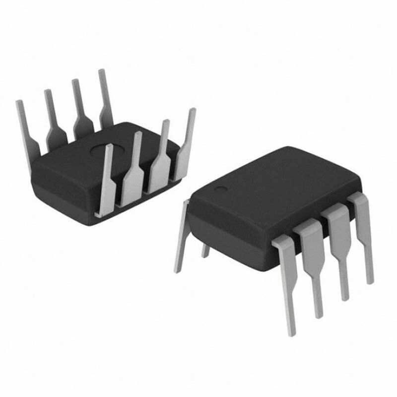
The little guy below is a 555 oscillator, does it look like a little crab? Crabs are definitely delicious in everyone's minds, but when asked to study an integrated circuit with the same number of claws as crabs, you may not have the patience.
Don’t worry, I will try to help you eat this small black box with only 8 pins like a crab.
![]()
You can check the specification here.
-
2Internal structure
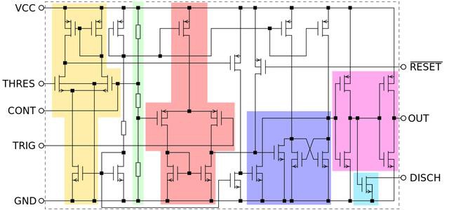
To know how an integrated circuit works, we first need to know its internal schematic diagram. The internal schematic diagram of the 555 oscillator is shown in the figure below.
Fortunately, there are not many internal integrated transistors, only 26. You have to know that the A12 X chip used in the iPad Pro integrates more than 10 billion transistors, and even the A12 of the iPhone XS integrates several billion of them. Although they are all chips, they are similar in size. It can only be said that the advancement of science and technology is so surprisingly fast.
![]()
For the above schematic diagram, it should be difficult to understand if you have not studied digital or analog electricity. Even if you have learned it, you may not be able to understand it. Although there are only 26 transistors, the knowledge involved is extremely wide, almost all of the university’s digital, electrical and analog electronics.
It doesn’t matter if you don’t understand it. The following is the simplified schematic of the 555 oscillator. The colored parts are modular, corresponding to the comparator and the trigger. Their names sound similar, but one belongs to the analog circuit, and another belongs to the number of electricity.
We only analyze the schematic diagrams now, not involving their construction principles, because if we talk about them, it is tantamount to relearning the analog electronics, and we may not be able to finish it with 10 articles.
-
3Principle block diagram
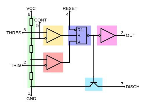
The simplified block diagram is very easy to understand. Each block diagram corresponds to the colored circuit in the figure above.
The yellow triangle and the pink triangle below are two comparators, and the purple one on the right is an R-S flip-flop.
The green ones on the left are three resistors with a resistance value of 5K. This is also the origin of the name of the 555 oscillator. There is also an oscillator with 556. Can you guess the difference with 555? At this time, you might say that in addition to the two 5K resistors, the other one is a 6K resistor.
Is it really like this? This is not the case. The 556 oscillator has an additional 1 than the 555, but this 1 does not represent the resistance of 1K, but two 555 oscillator modules contained in the 556. Such naming is truly surprising. If I were to name it, I might name 556 as 555D, and D represents double.
The picture below is a simplified diagram of the various functional modules inside the 555. It doesn't matter if you still can’t understand it, because we can use this 555 oscillator directly, even if you don’t know how it works.
![]()
-
4Pin
For beginners who are just getting started, you can use 555 to make a few small experiments, and then learn the bottom layer of 555. Through this kind of top-down learning, you are more able to understand your goal, otherwise you may even not know what you can do with what you have learned.
The quick way to learn this kind of module is to figure out the definition of its various pins, and then build a system, just like when we are learning programs, we have to print "Hello World".
![]()
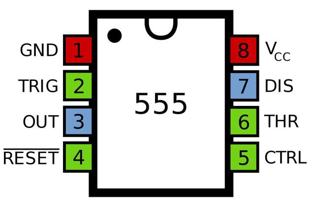
Next we talk about the role of each pin
Pin 1: negative pole of power supply
Pin 8: power supply positive
Pin 4: reset pin, connect the positive pole here
Pin 5: discharge pin, connected to the negative pole through a capacitor
So easy right? You have already learned half of the 555 pins, and then I will introduce the remaining four.
Pin 2 and Pin 6: The comparator control pin. These two pins are connected together, controlling the comparator according to the different voltage to output high low-level, thereby controlling the trigger.
Pin 7: It is connected between R1 and R2 with fixed wiring method. Now We don't have to care about it.
Pin 3: Pulse signal output pin, it is also a useful pin for us.
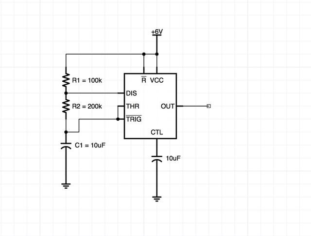
After we know the pin definition of 555, the next step is to build its system, for example, using it to control an LED to blink.
![]()
The system is as shown in the figure above, and there is only one step left to finish this project, that is, the load behind the OUT pin. Because our 555 can output more than 200 mA of current, it can drive the load, but some only output a pulse signal with a few milliamps of current, those 555 oscillators cannot drive a load.
Next, I connected an LED light to the OUT pin. As shown in the figure below, I connected an LED light to the OUT pin and a 1K resistor in series to limit the current.
![]()
Then the problem comes again. We know that the OUT pin of the 555 oscillator outputs a rectangular wave, but how to know its frequency?
This is very simple. The output frequency of the OUT pin can be calculated by R1, R2 and C1 in the above figure.
The frequency of the rectangular wave is f=1.44/(R1+2R2) C1
As shown in the picture above, our R1=100K, R2=200K, C1=10uF. So the output frequency of the rectangular wave f=1.44/(1000000+4000000)10UF=0.288HZ555
0.288 is the frequency, converted to period: 1/0.288=3.4S, which means that the LED light changes state every 1.7S.
For this circuit, I built the actual circuit with a breadboard, and the experimental results are consistent with expectations.
-
5Experimental phenomena
The LED light changes state almost every 1.7 seconds. How about it? I guess you can’t wait to try it yourself. Just do it!
Build LED blinking circuit with 555 oscillator
This project is to build an LED flashing circuit on a breadboard.

Discussions
Become a Hackaday.io Member
Create an account to leave a comment. Already have an account? Log In.