NotBlackMagic
-
Software Update
12/09/2020 at 09:30 • 0 commentsOver the past few months, I changed many small things in both the STM32G4DAQ Firmware as well as on the PC Software side.
Firmware
On the firmware side the Analog Output software handling was improved. The already used circular buffers that feed the DACs through DMAs were moved from the main SRAM1 to the smaller and separate SRAM2. This change allows for the processor to access and process data from SRAM1 simultaneously with the DMA accessing the circular buffers in SRAM2. This removes concurrent memory access wait states and therefore performance of the main code execution.
The other change to the firmware was adding the control and acquisition for the Analog Input Block B. Now both the Analog Input Block A and B can be used, simultaneously, which allows for two full speed acquisition channels of up to 62.5 ksps or up to 8 differential, 16 single ended, acquisition channels.
PC Software
On the PC Software side, the main change was switching the graphing library from the previously used LiveChart to the open source ScottPlot which is simpler and much much faster. For an idea of how much faster, with LiveCharts, it was difficult to get Graph refresh rates of 1 Hz when displaying big swing, full range, graphs. With ScottPlot this is now easily possible, currently I'm using a refresh rate of 10Hz which works very well and can be increased (drawing 2 sets/plots of 512 points each).
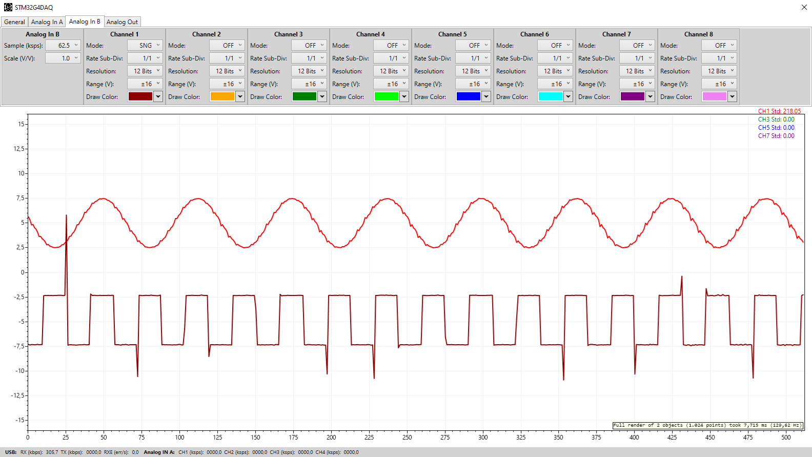
The other addition was the needed new Tab for controlling the Analog Input Block B, as well as adding the funcitonality of changing Graphs line colors. This new Tab as well as the new look of the graphs using ScottPlot is visible in the image bellow, it also shows the drawing speed of ScottPlot:
![]()
Next steps will be focused on discovering the cause of the still present spikes in the acquired signals as well as working on the Digital IO port. A new Analog Output OpAmp will also soon be tested, as soon as it arrives.
As always, all this and more can be found on the website. A new addition, not shown here, is the interface protocol used to control and communicate with the DAQ. I also try to give more frequent and smaller updates over on Twitter.
-
PC Software: Analog Output
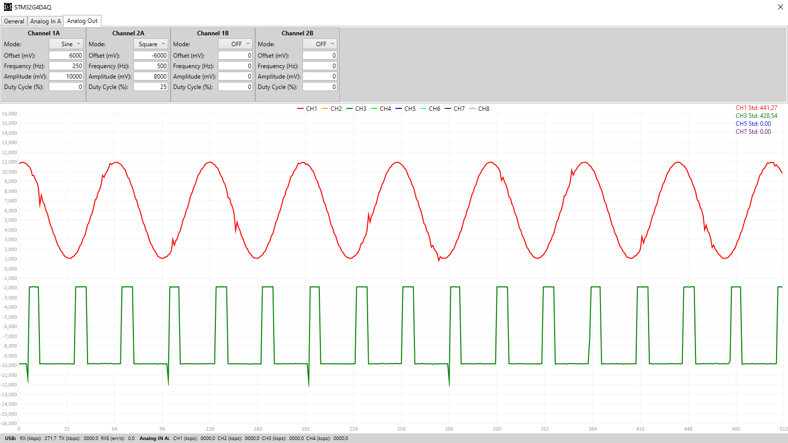
09/22/2020 at 21:57 • 0 commentsThe last week was spent on improving the signal generation functions of the PC Software. All signals are now generated with a variable number of sample points that scales with the signal frequency. A minimum of 20 points is used, at the highest signal frequency of 100 kHz, and this scales up to a maximum of 100 points for signal frequencies of 10 kHz or lower. The figure bellow shows a sine wave with the increased number of points, here 100, as well as a new type of signal that the PC Software can now generate, square waves.
![]()
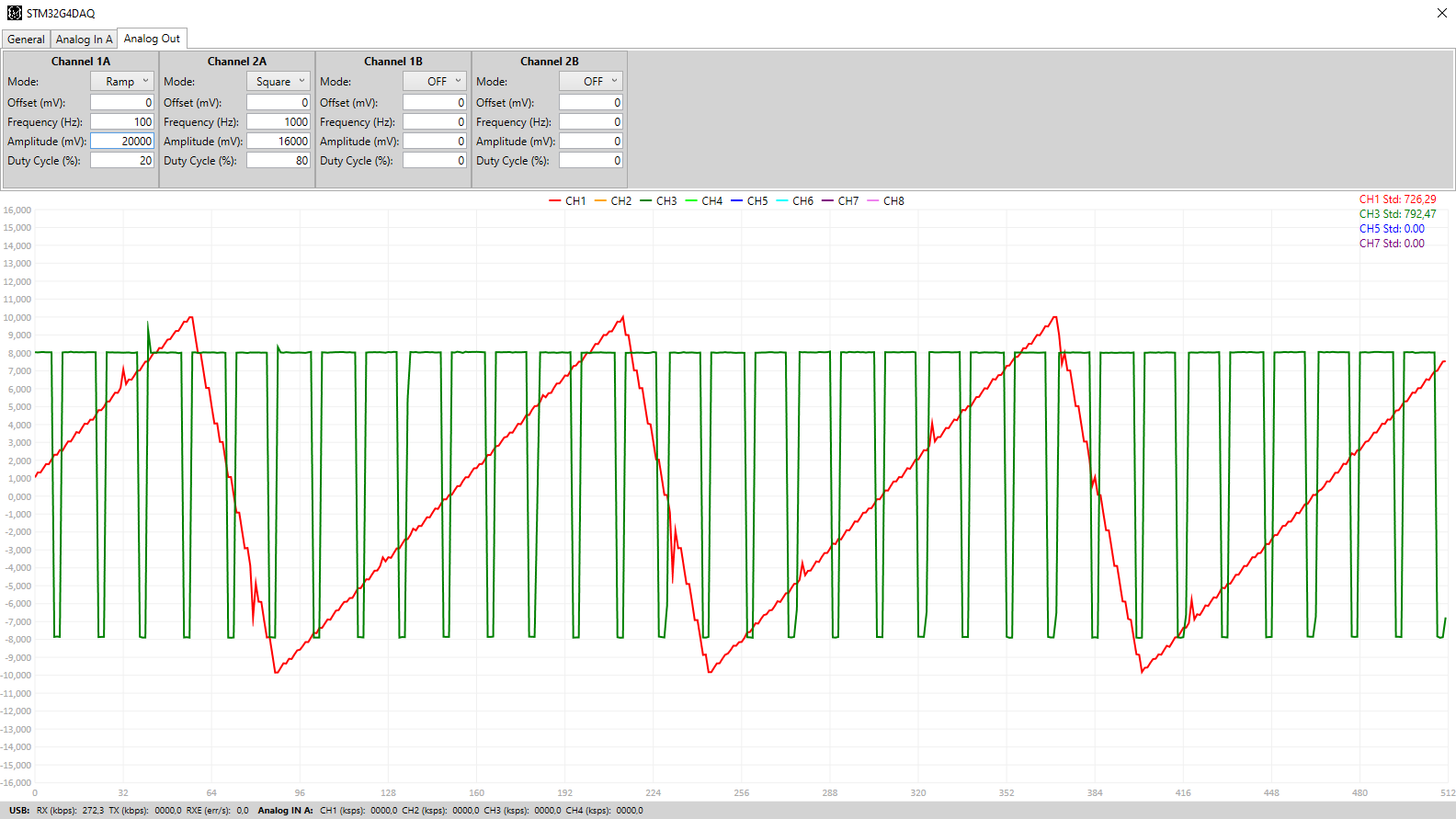
Besides the improved sine wave generation and the added square wave signals, a ramp signal generation was also added. The ramp center point, highest point, can be configured with the duty cycle parameter. The Figure bellow shows an example of a generated Ramp signal as well as another square wave:
![]()
Both the above images are taken with the DAQ sampling its analog outputs.
The current PC Software is available on my GitHub page. For more information and more figures visit my website.
-
Analog Input Noise and PC Software
09/16/2020 at 16:18 • 0 commentsAnalog Input Noise
During the last few weeks, using the PC Acquisition Software, the analog input noise was analyzed. For now only of the Analog Black A but the values should be the same as the hardware and layouts are the same. To get the baseline noise level one analog input channel is configured in differential mode and its inputs are shorted. The standard deviation of the acquired ADC samples is then calculated, this gives us the input noise in ADC counts. In this test scenario a standard deviation of bellow 2 counts was measured, for all ranges and sample rates.
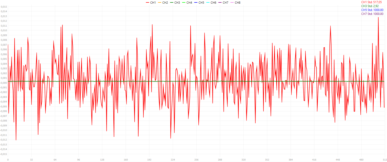
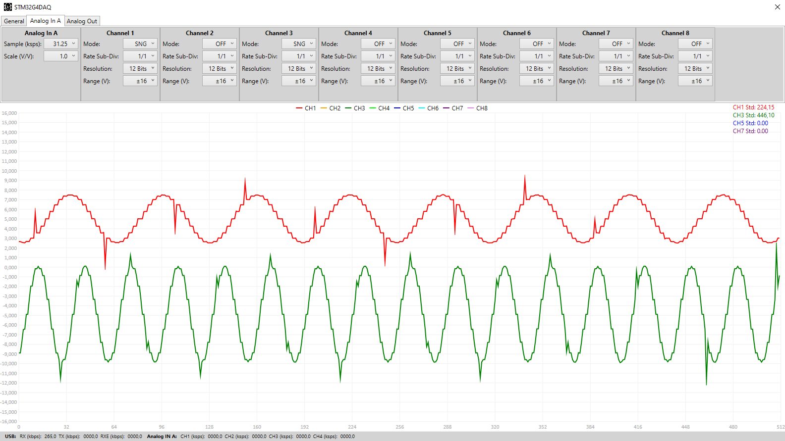
To get an idea of cross-channel interference the same test as described above is performed, but this time a full range noise signal is injected into an adjacent channel. The output of this scenario is shown in the figure bellow, showing a screenshot of the PC Acquisition Software Window. The noise/standard deviation is bellow 3 counts on the tested channel, in green. The noise signal is visible in red.
![]()
Overall, in all tested scenarios, ranges and sample rates, the standard deviation was always bellow 4 counts which means that the DAQ has a worst case effective resolution of 10-bits.
PC Software
As seen above, the PC Acquisition Software is now functional but with a lot of limitations. It is capable of configuring both the Analog Inputs and Output of the Analog Block A. The Analog Input acquisition window refresh rate is very low, only refreshed every 1s, but the PC DAQ driver receives and saves the samples in real time without problems. The limitation is on the Graph Drawing, which needs to be optimized.
The Figure bellow shows the PC Software with the Analog Input Menu open. The signal shown is generated by the Analog Output channels 1 and 2 and is acquired by the Analog Input channels 1 and 3, using the settings shown in the figure.
![]()
The Analog Output signal generation can, for now, only generated DC signals and sine waves with 20 sampling points, as can be seen in the figure bellow. Also, at high sample rates, the acquired signal sometimes has the spikes seen in the figure above. It is not clear yet what is the origin of them...
The PC Software is available on my GitHub page.
For more information and more in-depth explanations visit the website. I also sometimes publish sneak peaks and pictures of project progress on both Instagram and Twitter.
STM32G4 DAQ
A DAQ with 8 Diff/16 Sin. Ended +/- 12V input channels and four +/- 12V output channels using the STM32G4