-
1PARTS AND MATERIALS REQUIRED!!!
- *ARDUINO UNO (It is highly recommended to use arduino nano i doesnt had the nano so i have used uno)
- *ULTRASONIC SENSOR
- *A BUZZER
- *A LED
-
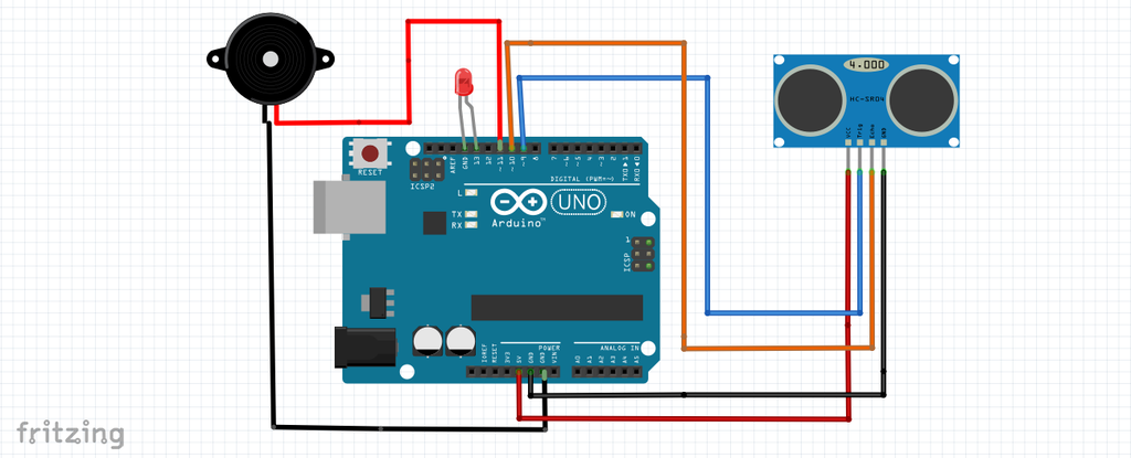
2CIRCUIT DIAGRAM FOR THE CONNECTIONS!!!
![]()
-
3NOW ITS TIME TO UPLOAD THE CODE!!!!
//Dynamic Innovator const int trigPin = 9; const int echoPin = 10; const int buzzer = 11; const int ledPin = 13; // defines variables long duration; int distance; int safetyDistance; void setup() { pinMode(trigPin, OUTPUT); // Sets the trigPin as an Output pinMode(echoPin, INPUT); // Sets the echoPin as an Input pinMode(buzzer, OUTPUT); pinMode(ledPin, OUTPUT); Serial.begin(9600); // Starts the serial communication } void loop() { // Clears the trigPin digitalWrite(trigPin, LOW); delayMicroseconds(2); // Sets the trigPin on HIGH state for 10 micro seconds digitalWrite(trigPin, HIGH); delayMicroseconds(10); digitalWrite(trigPin, LOW); // Reads the echoPin, returns the sound wave travel time in microseconds duration = pulseIn(echoPin, HIGH); // Calculating the distance distance= duration*0.034/2; safetyDistance = distance; if (safetyDistance <= 22 ){ // Enter the Distance digitalWrite(buzzer, HIGH); digitalWrite(ledPin, HIGH); } else{ digitalWrite(buzzer, LOW); digitalWrite(ledPin, LOW); } // Prints the distance on the Serial Monitor Serial.print("Distance: "); Serial.println(distance); } -
4TESTING THE CONNECTIONS AND THE CODE!!!
After uploading the code now its time for the testing of the sensor
bring your hand in front of the sensor the buzzer and the led activates!!!
![]()
-
5FIXING THE SENSOR,LED,BUZZER TO THE CAP!!!
FIX the arduino to the back strap of the cap with the help of some rubber bands.
- and fix the ultrasonic sensor infront of the cap.
- and fix the buzzer back side of the cap.
-
6WATCH THE VIDEO FOR WORKING AND MORE DETAILS!!
ALSO SUBSCRIBE AND LIKE THE VIDEO!
The Cap That Doesn't Let You Touch Your Face!!!
This is a anti face touch alarm cap that doesnt allows to touch your face.. this is a trainer cap to not to touch our face!!!

Discussions
Become a Hackaday.io Member
Create an account to leave a comment. Already have an account? Log In.