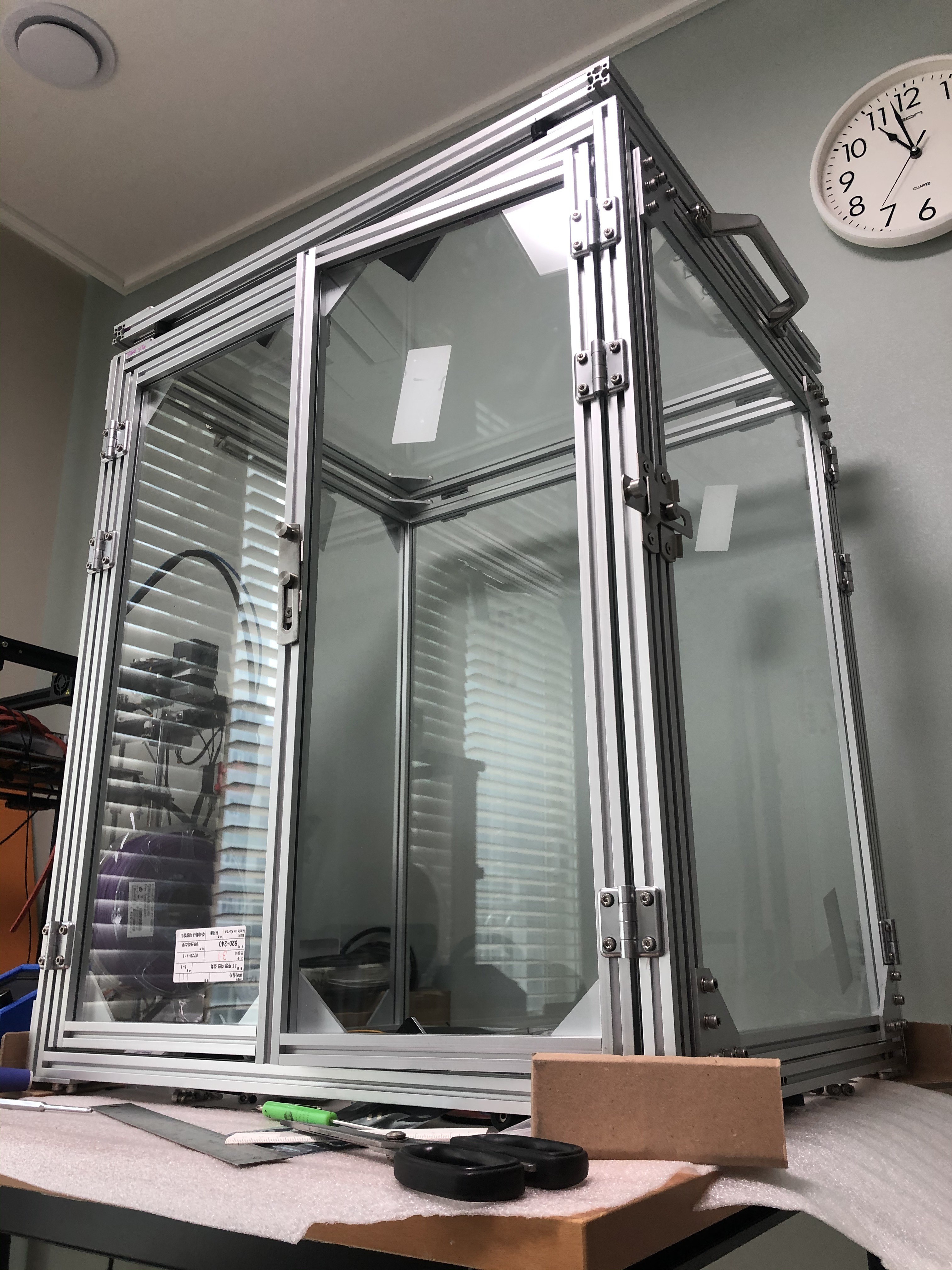
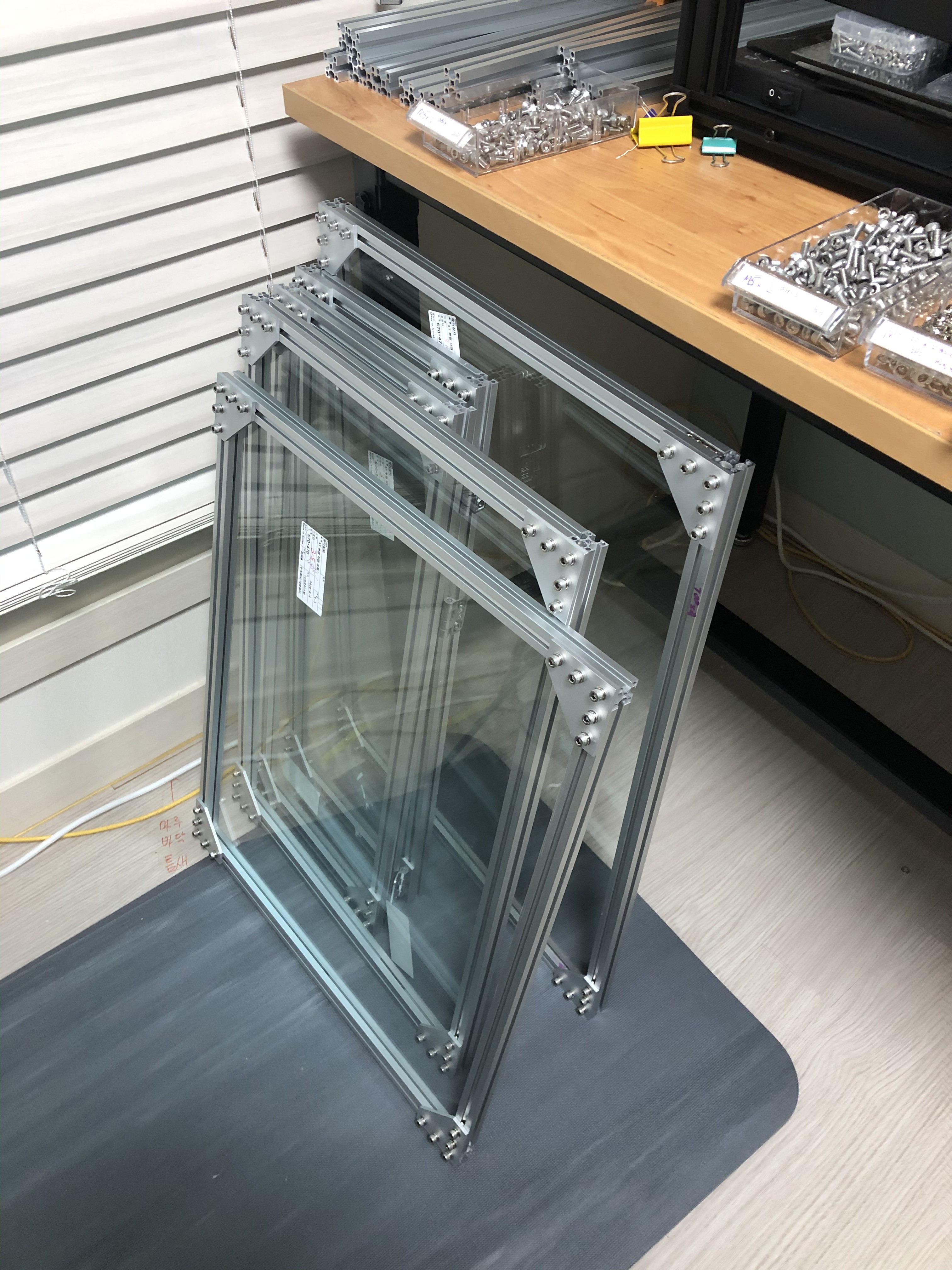
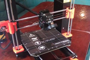
A gray-headed electrical engineer ventures outside his comfort zone by building a sturdy enclosure for a Ender 5 Pro 3D printer. This project has gone from "how hard could it be" to "I may have bitten off more than I can chew". But success is in sight. I made a test door panel to prove the concept (see gallery). All the hardware pieces have arrived, and the extrusions and glass panels will arrive next week. Drawings are 75% complete, and will include DXF, OpenSCAD, and a spreadsheet BOM, including a rambling narrative with photos.
Details
Check the GitHub repo for the more details where I've updated notes about the design, assembly instructions, and other material.
Files
cage-panel.pdf
Engineering drawing of the basic frame/panel, which is the building block of the design. DWG and DXF files can be found in the repository.
Adobe Portable Document Format -
182.84 kB -
09/02/2020 at 00:59
Project is once again done, but not before I had another measurement scare. As I was working on the front door hinges, I realized the doors wouldn't close! The glass was hitting the frontmost piece of the printer (two timing belt pulleys on the top front corners). My measurement of the 3D printer was not accurate enough. I was very lucky -- the error was very small. The depth of the cage only needed to be about 10 mm deeper. I was able to pick up this extra depth by changing the framework of the rear face from 2020 extrusion to 2040. This gave me an extra 20 mm depth, more than enough, the the only down side is that the top lid is a little short, but even that I could fix if it worries me too much down the road.
If you have an Ender 5 and want to build this kind of cage, I would increase the depth by more than 20 mm, just to give a little more margin. I would probably bump the depth say 50 mm?
Belatedly wrapping this up. There are still small tweaks I'd like to do here and there, but that will never stop. Updated drawings, pictures, and provided assembly instructions. Check out the repository.
Added some design details to the repo. Been working on an exploded view render from OpenSCAD. Should have it ready tomorrow. Work and a nearby typhoon delayed final assembly of the cage another day or two - that's life.
As I started to assemble the first panel tonight, I found yet another mistake. I ordered two of the larger panels incorrectly. In this case, it was an error when I rolled up the various Parts Lists into a to-purchase BOMs. It was an extremely unlucky typo - neither of the two panes were the correct size.
Ordered:
2 ea 640 x 470 mm panes
Needed:
1 ea 670 x 470
1 ea 670 x 570
I will plow ahead building what I can, new panes on order, should arrive before Friday if I'm lucky.
Did some cleanup of the files and organization, pushed a project repository on GitHub. This repository includes some more photos (I think I've maxed out the gallery space on Hackaday.io), the OpenSCAD files, and a 2D CAD drawing ( DWG, DXF, and PDF) of the panel. The panels form the basic building blocks of the design.
Yet to do, documentation-wise:
complete and upload the final assembly drawing
notes and comments on the design
explanation of some of the OpenSCAD craziness
As for the enclosure, the remaining six rails of the correct length will arrive today. I will start assembling everything tonight. I should have it assembled and running by the weekend, knock on wood.
Almost all the remaining parts arrived Friday. A bundle of cut-to-length 2020 profiles, and the tempered glass panels. See gallery.
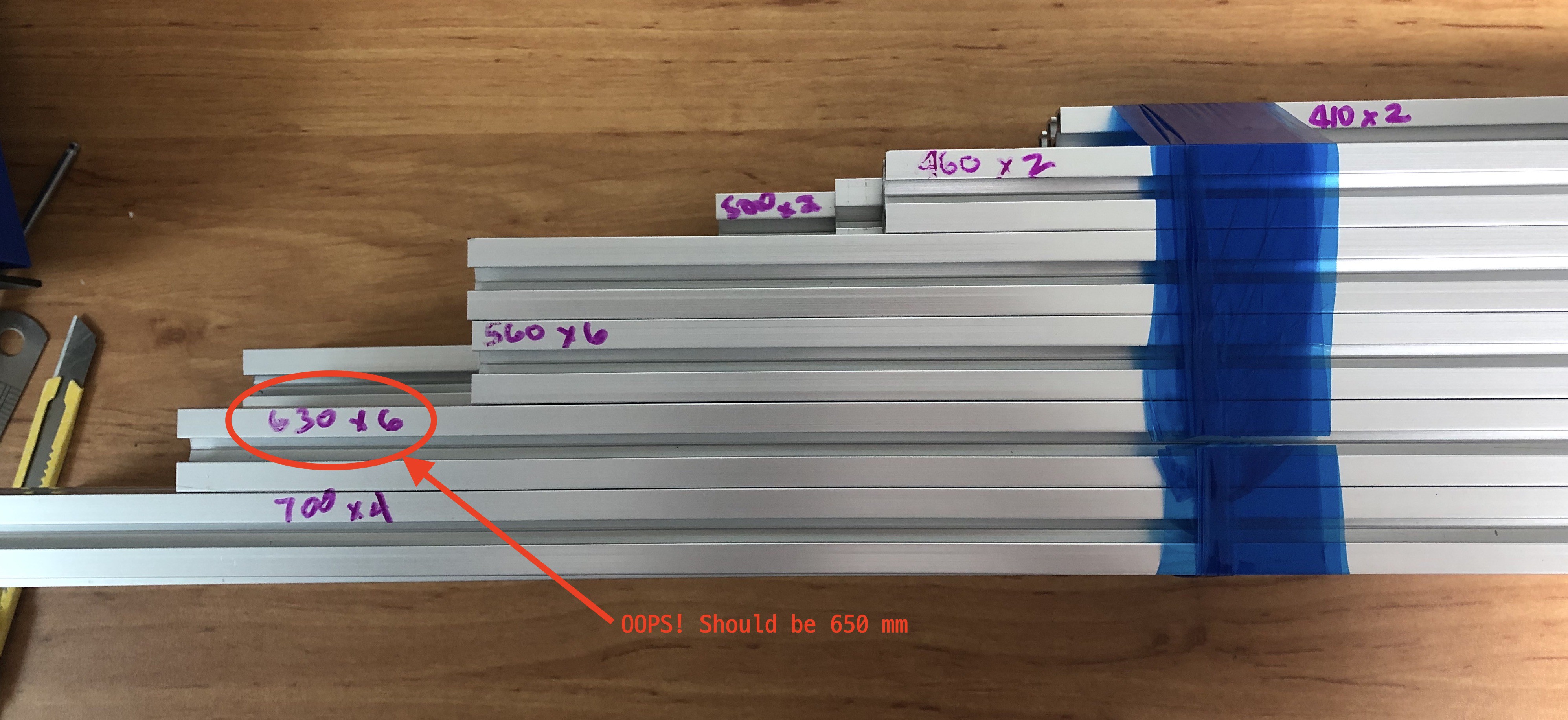
Despite triple checking my numbers, I mis-ordered on length of profile, requesting 630 instead of 650mm. Corrected pieces ordered Saturday, should get here Monday or Tuesday.
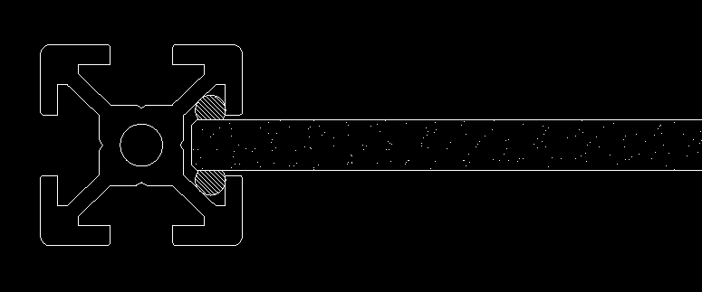
I also had one heck of a time with gasket materials to keep the glass securely in place. As you will see (when I finally upload my drawings), I had a careful plan that a pair of 3mm gaskets with circular cross-sections would be perfect. Alas, it proved to be a bear to install them. First problem was how to install the gaskets. I basically had two cylindrical rubber "ropes" that I had to squeeze in between the glass edges and the insides of the 2020 profile. This was proving to be quite awkward. The second problem was even when I had only one gasket installed, the force required to bring the frame corners together was scary.
In the end, I decided this idea was overkill. Unlike ordinary gaskets on windows, whose goal is to prevent leaks, in my application the main function is to just keep the glass from rattling in the frame. I pulled most of the gasket material, and just left a short pieces along each edge. Problem solved.
This discussion might be getting ahead of myself, since I still haven't posted drawings yet, but you can get the idea of the problem from this sketch above and picture of the test panel in the gallery (that test panel didn't have any gasket, and taught me that I needed one).
I've been curious for some time about 3D printers, but never took the plunge until the virus hit. Back in March, a friend of mine pointed out that he was making miniature people, cars, and buildings for his HO-gauge model railroad layout using a $300 printer from China. I knew the time had come. His model was the Ender 3, but I splurged and got the Ender 5 Pro.
Shortly after receiving my new printer, another friend told me I needed an enclosure, advice that I kept putting off until I realized he was right. After doing a little research, I wasn't really impressed with any of the off-the-shelf solutions. Having an enclosure that was not flammable seemed to be desirable, but many of the popular ones weren't. Building my own seemed an option, but I imagined complex 3D pieces to join panes of glass together at the corners began to worry me. And any "good" enclosure needs doors, panels, mounting points for accessories, etc.
Then suddenly, I had an idea ... use the same type of aluminum extrusions that comprised the 3D printer as frames for a glass enclosure. and it seemed much more approachable. This hack page will force me to document my project, and hopefully nag me to wrap it up sooner than later.
The main design is locked in. I was a little worried about a few educated guesses I made in the design, so I built a small test panel. Surprisingly, everything went together as expected. The only tweak was one I had planned for, that was selecting the type and size of packing to keep the glass from rattling in the frame. I have all the hardware in-hand, and pulled the plug on the extrusions and glass panels yesterday.
I have a substantial part of the documentation already completed. This includes a BOM, with part information and data sheets, and CAD drawings in DWG/DXF format (assembly drawings) and OpenSCAD for 3D modeling and exploded view animation. I'll try to post an update every couple of days until it's all built and in-service.