-
Flip-flop in detail
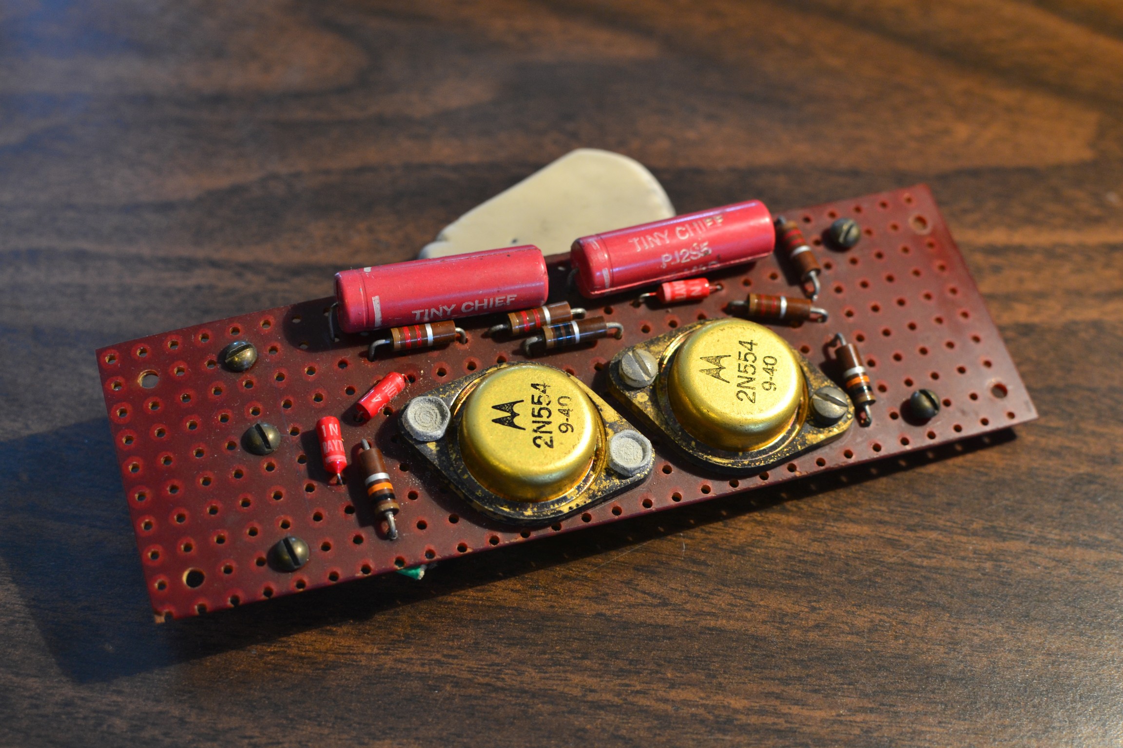
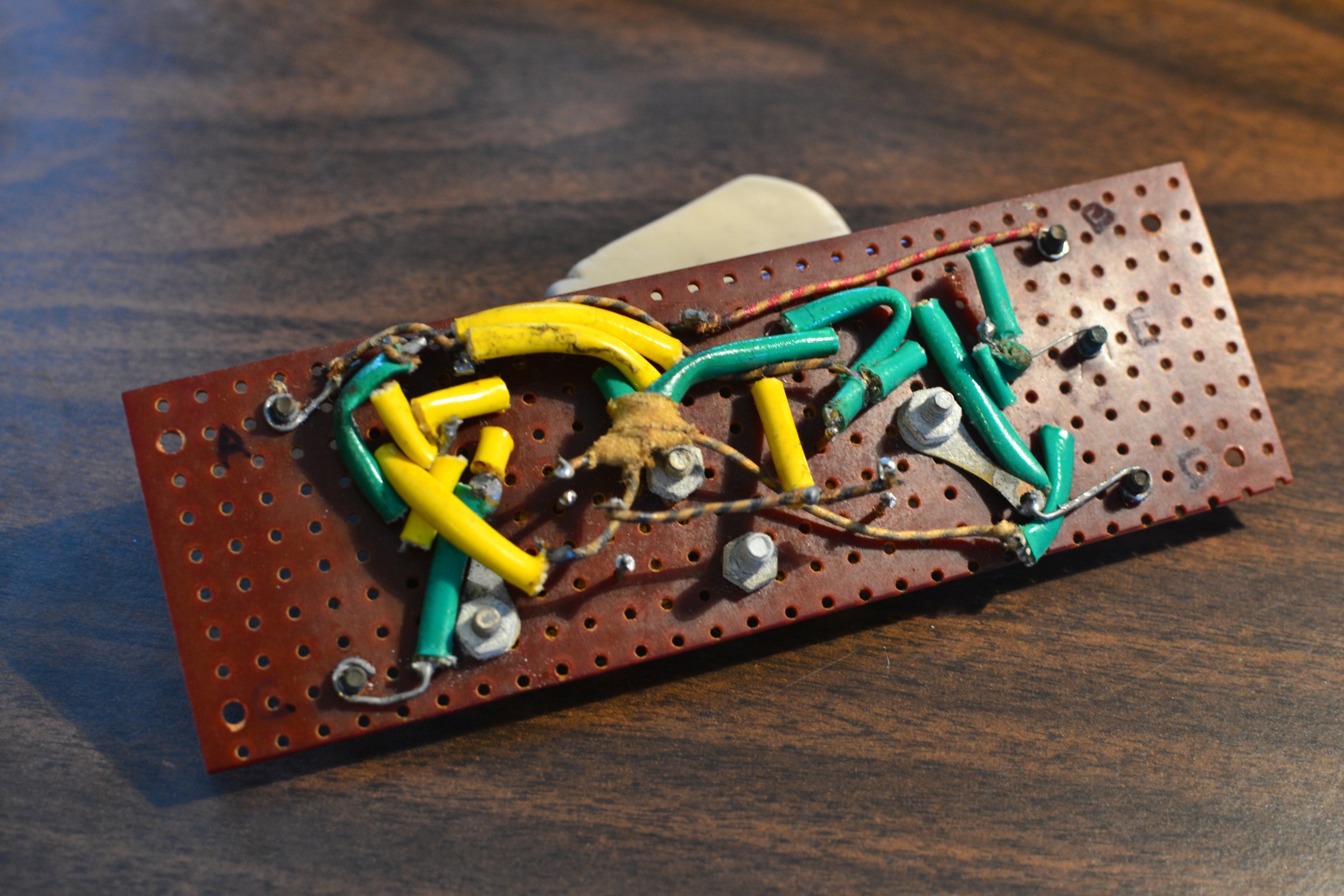
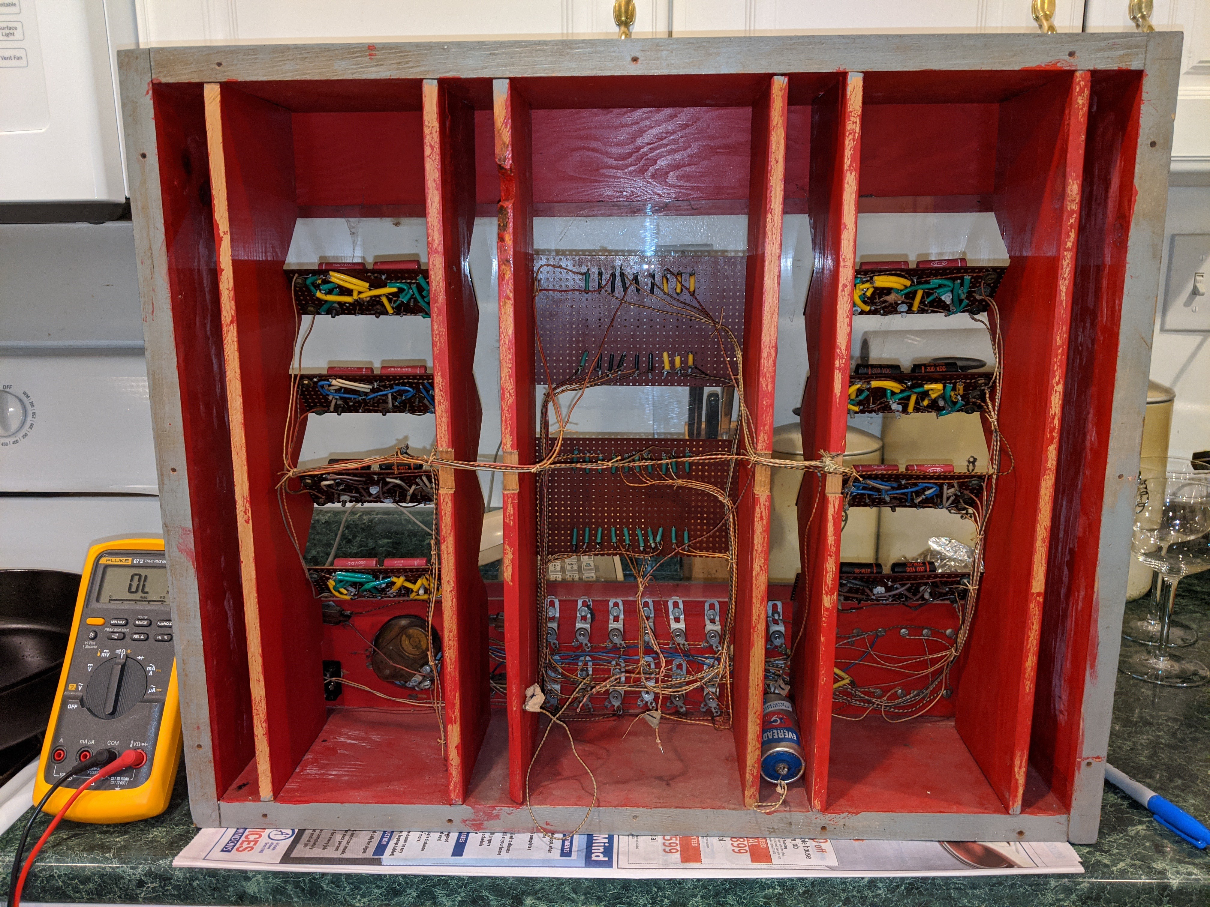
09/07/2020 at 20:37 • 1 commentHere's a closeup on one flip-flop module (#1 in the machine's sequence, or top-left as seen in the main photos.) The construction obviously shows skill, although I'm guessing not a lot of formal training. Lots of odd wiring choices that I feel like could have been done in a more straightforward way. He was a fan of compound joints with many connections coming together.
In that pic I have a few joints desoldered for testing purposes. Another odd choice is that two of the other modules have their transistors installed upside down. Rather than just flip them over to make all the units identical, he wired those two modules in mirror fashion--confusing. I can't tell if they all were made at the same time or not. The parts aren't identical from unit to unit but whether that means they were done at different times or just used whatever was on hand I can't say.
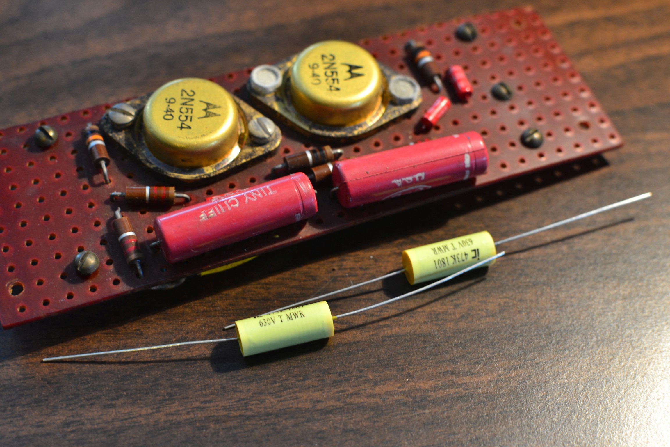
All the original caps have drifted way off, but the resistors check out and the transistors seem OK, although with a little more leakage than you'd want in a modern piece. Some people have brought up keeping the original caps for aesthetic reasons and hiding the new ones. I don't really mind the new ones and I like the snazzy yellow, but what're your thoughts? I'll rebuild this soon and test it out.
-
Getting my flips to flop?
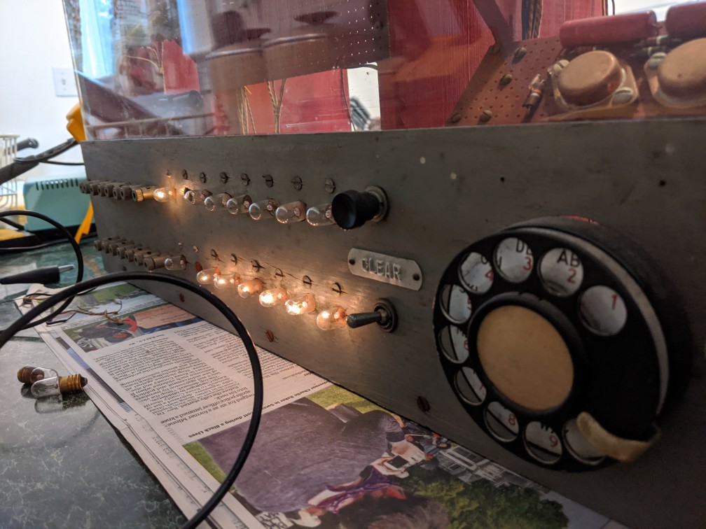
08/27/2020 at 17:57 • 0 commentsThe core of this thing are eight bistable flip-flip modules each based around two germanium 2N554 transistors. As-found the machine will power up and illuminate some of the output lights, but the flip/flip triggering is very erratic. Most modules need to be triggered multiple times before switching outputs. Any readers have thoughts on the problem?


Naturally he original sealed paper .05uF 100V capacitors are all suspect at this age. Most measure several times the rated capacitance and show signs of electrical leakage. My first experiment was replacing the caps in one module with a pair of random (0.85uF) known-good films caps I had on hand. The triggering improved a little but is still very unreliable. Correct caps have been ordered, but I'm wondering how much could a drifted cap affect the circuit's function?
-
Discovering the electronic layout
08/27/2020 at 17:26 • 0 commentsThis machine appears to have been built using the Jan 1960 Electronics Illustrated version of the plans as the starting point. Other magazines such as Popular Electronics have different descriptions of the same fundamental circuits. Member @Yann Guidon / YGDES has published several logs going into the historical detail of the design.

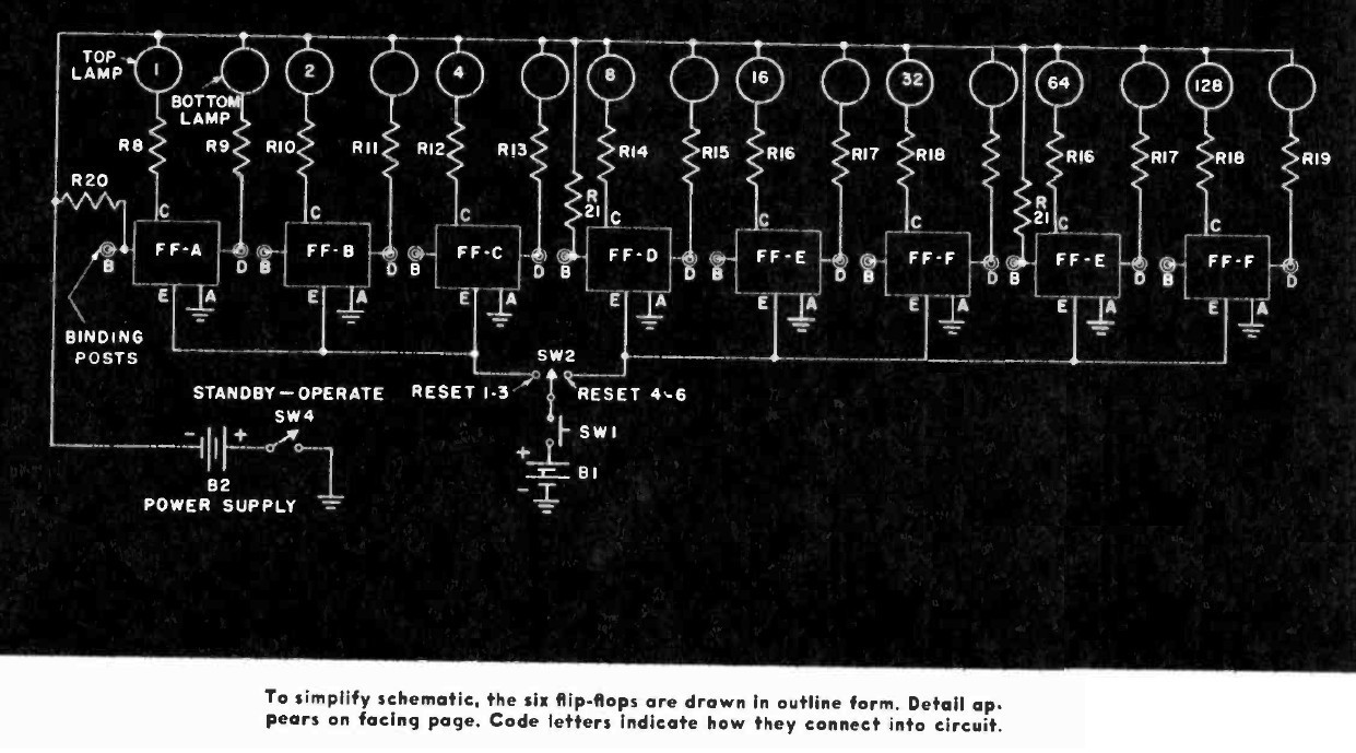
Compared to the published machine, the Transbiniac has two extra flip-flop modules and a supporting 10K resistor, the multiplication circuit is gone, some of the wiring has been simplified, and there's no AC power supply. I've altered the original overall schematic to reflect the added modules:

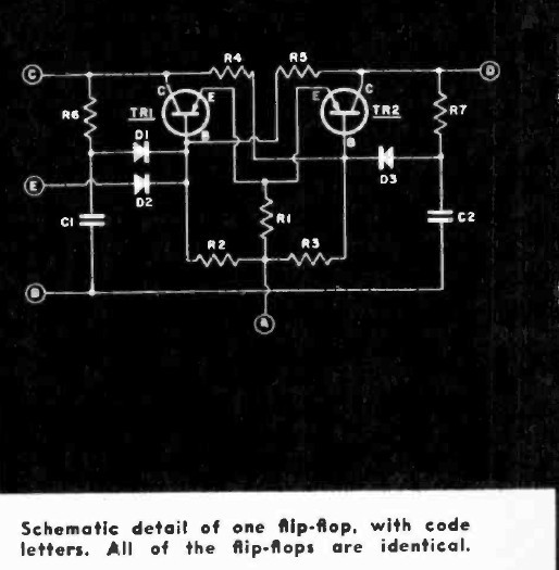
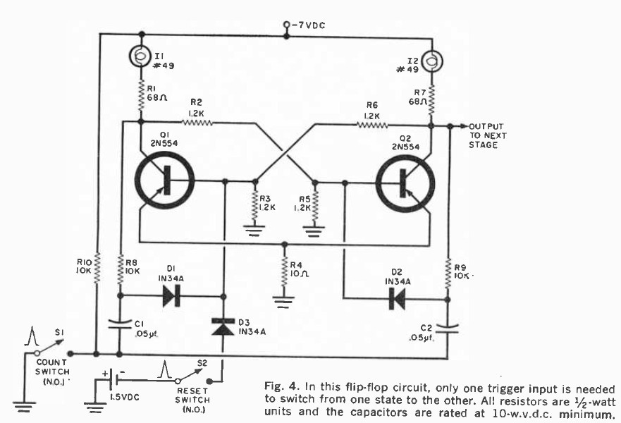
The flip-flops themselves appear to be unchanged from the original published designs. One from the Electronics Illustrated article and another from the March 1961 issue of Popular Electronics:


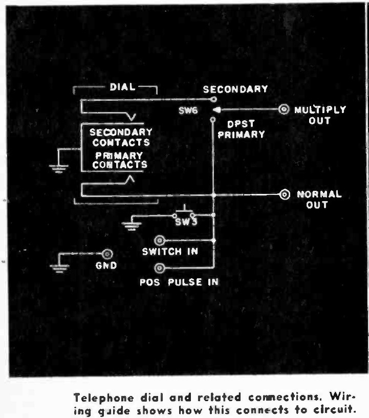
The last change/difference is one I can't tell if it's intentional or not. The original plans call for a normally open trigger circuit consisting of a momentary switch plus a rotary telephone dial. In my machine, the switch and the rotary dial are both wired as NC and don't appear to work in that configuration. My dial also doesn't appear to have the same switch type as the published plans, but my vintage telephone kung fu is pretty weak.

Restoring the TRANSBINIAC computer
Bringing a vintage DIY binary counting computer back to life
