-
Software Features, User Interface and Prototype
11/20/2020 at 16:06 • 0 commentsTo start off, thanks to the video sponsor: JLCPCB for sponsoring this project. JLCPCB Prototype for $2 (Any Color): https://jlcpcb.com
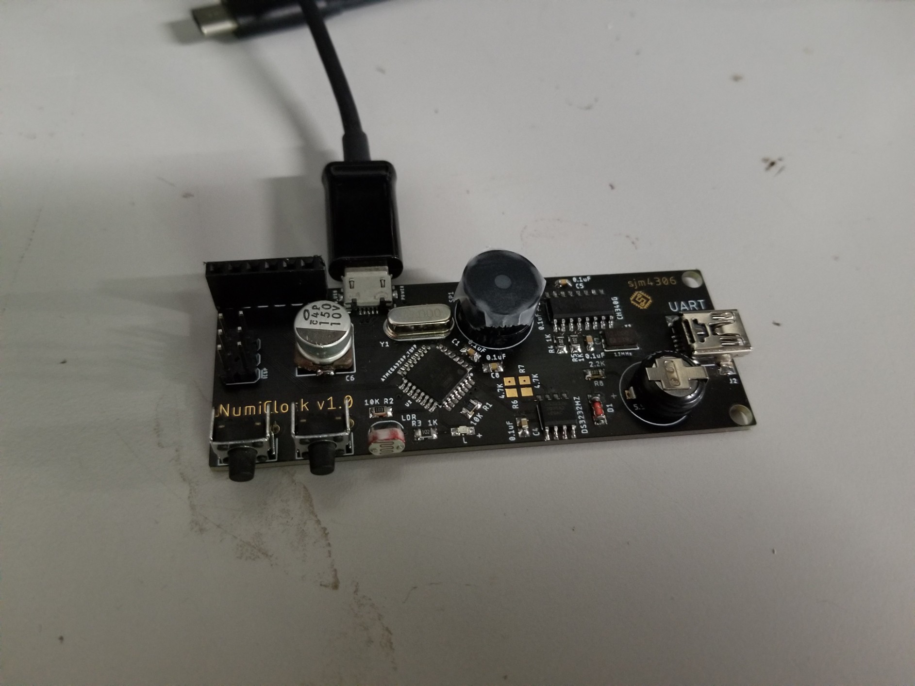
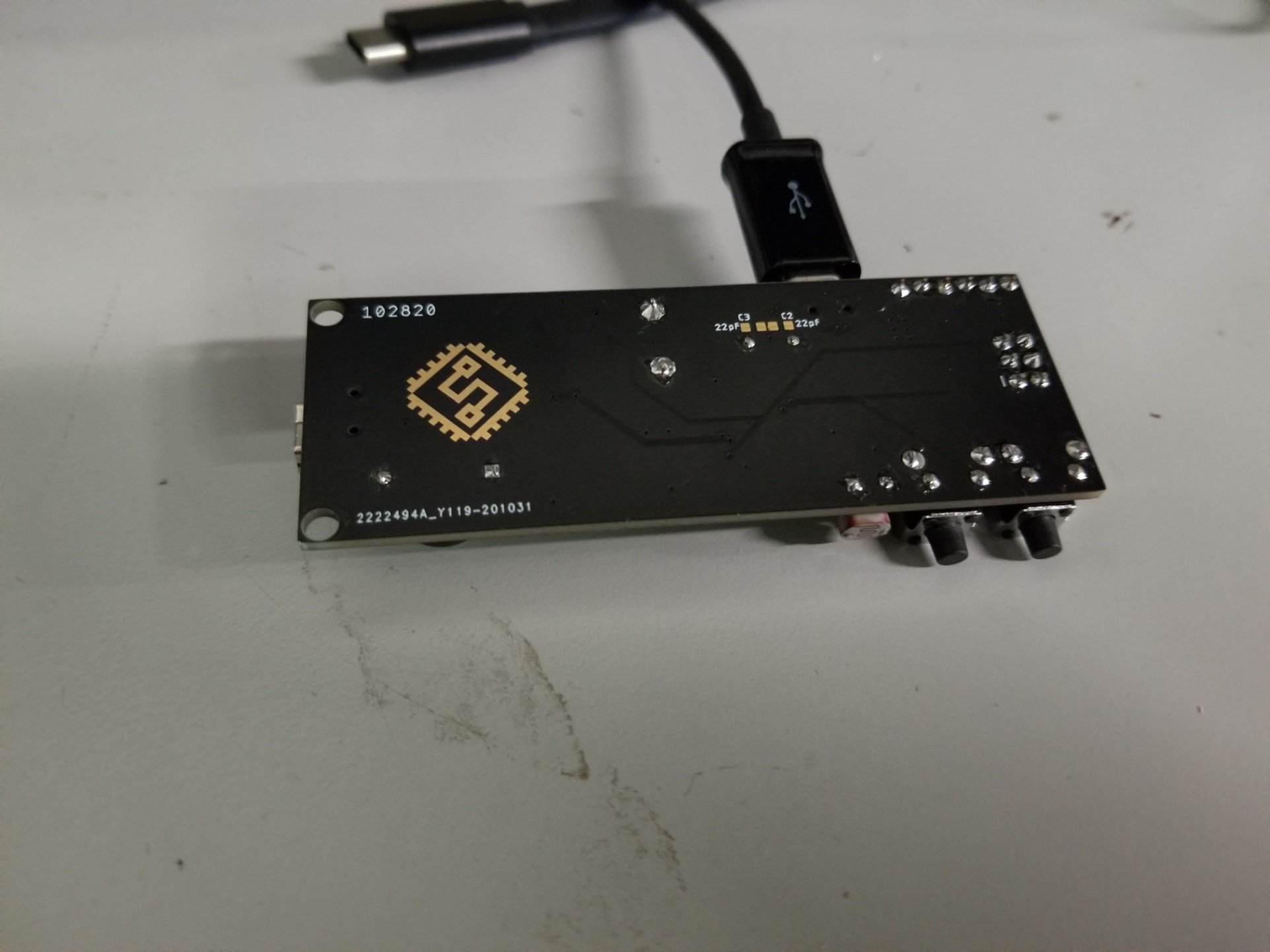
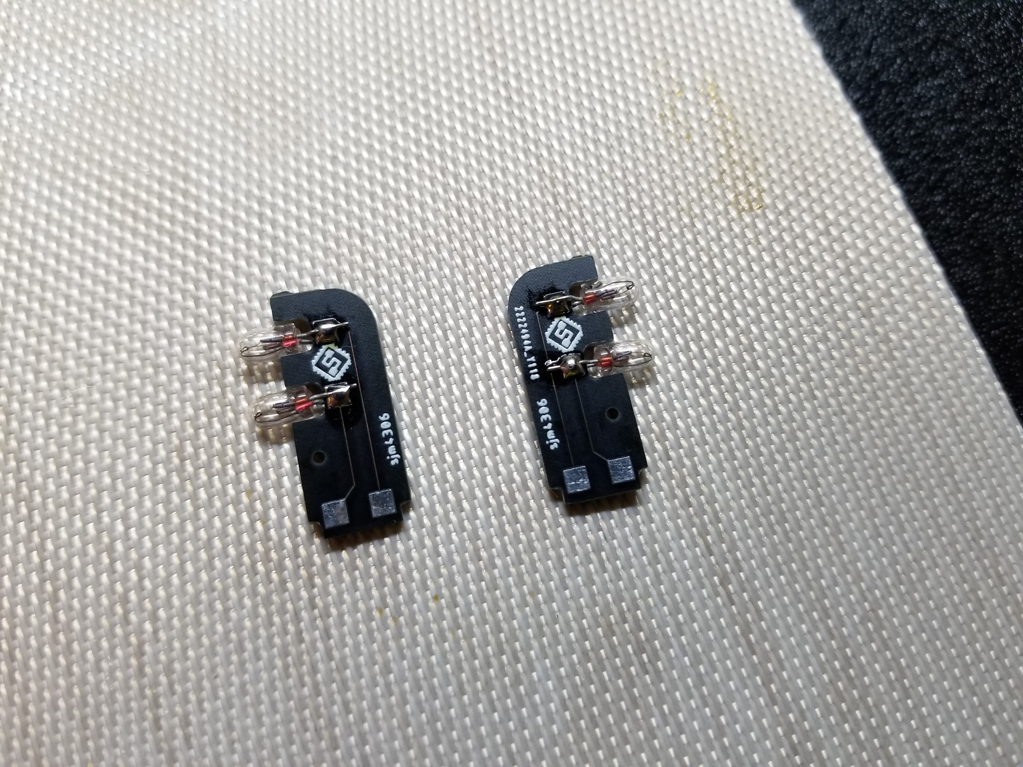
The main clock board arrived pretty quickly thanks to JLCPCB (along with the tiny vertical colon bulb holders pcbs) so I set off assembling and testing them.
![]()
Top of assembled main board
![]()
Bottom of assembled main board
![]()
Aren't these little vertical bulb boards adorable? I should've included a banana in the pic for scale ...
One annoyance I found (which was 100% my own fault) was the CH340G usb serial chips I purchased from eBay ended up being fake (much surprise, very gasp!!!). Luckily I had a few extra from a past order that I knew worked. Note to future self, don't cheap out and buy from questionable sellers. Ah well, lesson learned and I got my money back.
I've finally moved on from the DS1302 RTC I've used in just about every previous clock. The accuracy using the external 32.768k crystal is pretty bad (on the order of +/- ~12ppm), overall being off by a few minutes over the course of a few weeks. I did a quick search and found the DS3232M which has an internal temp compensated MEMS oscillator (+/- 5ppm out of the tray, can be trimmed in software for greater accuracy), the same easy to solder soic-8 package, i2c interface, 256 bytes of sram, and battery backup (though oddly no charging like the DS1302, but an external diode and resistor quickly solves that).
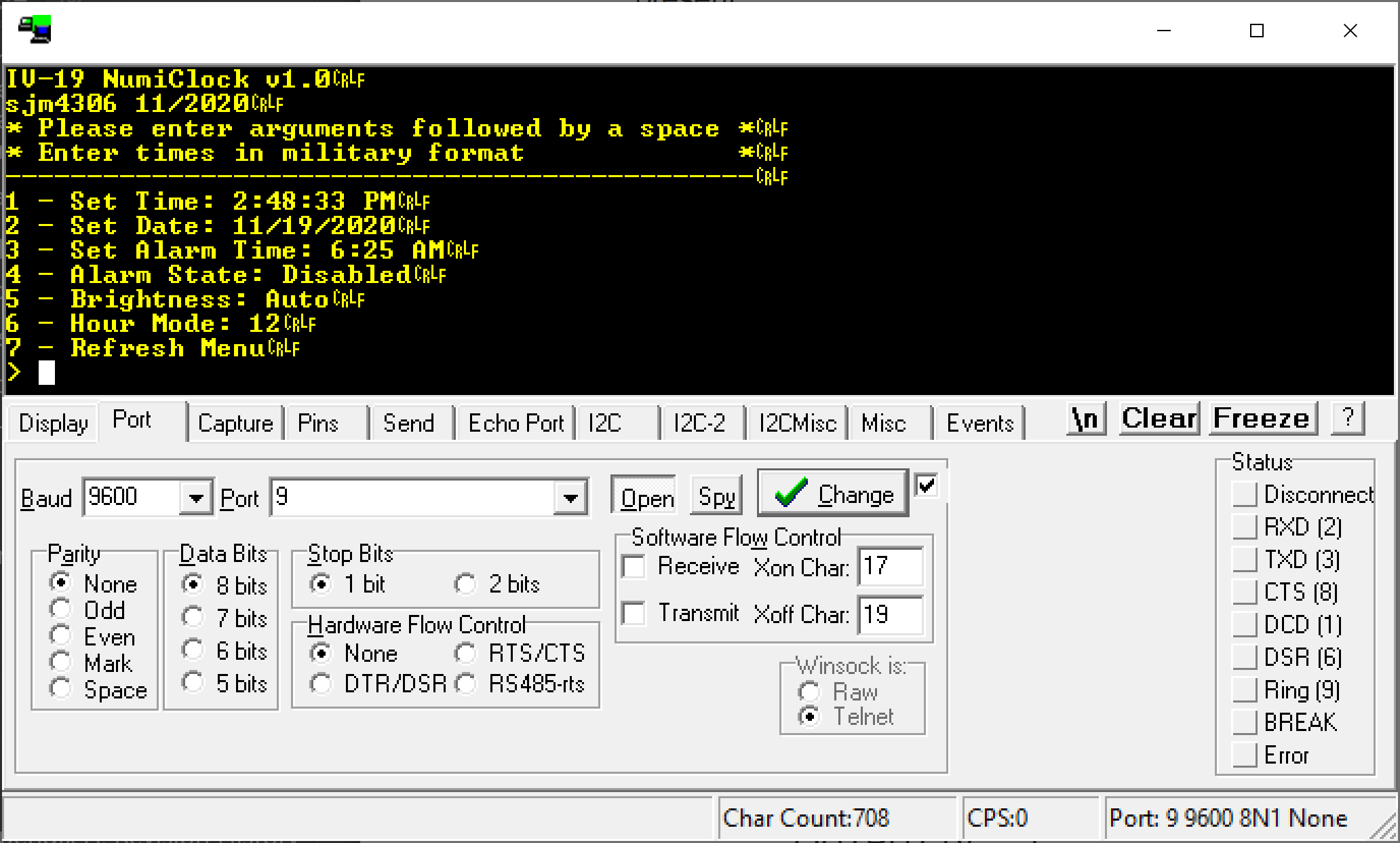
My first step was to write some new software to talk with the new RTC and print out debug info over serial. In fact I went a bit further and programmed a serial menu system that allows complete control of all settings using nothing more than a usb connection and a serial terminal. In addition, it'd be trivial to attach a serial bluetooth or wifi module to allow wireless control (I added a second mini usb port on the main pcb with direct connection to the serial pins of the atmega to allow modular connection).
Realterm used to display the serial menu connected over usb
Additionally I finally added an ambient light sensor to a clock, so it was a simple task of mapping measured raw values in the range of ~183-960 and map them to 128-255 pwm (which happens to be inversed since the output enable pin on the shift registers that control the tubes is active low). I couldn't gone fancy by using a lookup table or even fancier by using a nonlinear or piecewise linear function to approximate the human eye response, but I want lofi and just used y=mx+b to find a line segment which corresponded to the measured points with the values I measured. The brightness equation then came out to y (pwm) = -0.163*Raw_ADC_Value + 285. When updated at a 10Hz sample rate this results in very silky smooth brightness adjustment with little noticeable response nonlinearity.
Another new feature I added was having a user settable alarm (I know it took me awhile to add this to my clocks, but I actually do plan on building a case for this and using this as an alarm clock). The onboard piezo isn't very loud so I will have to test if it can wake me from my usual deep slumber.
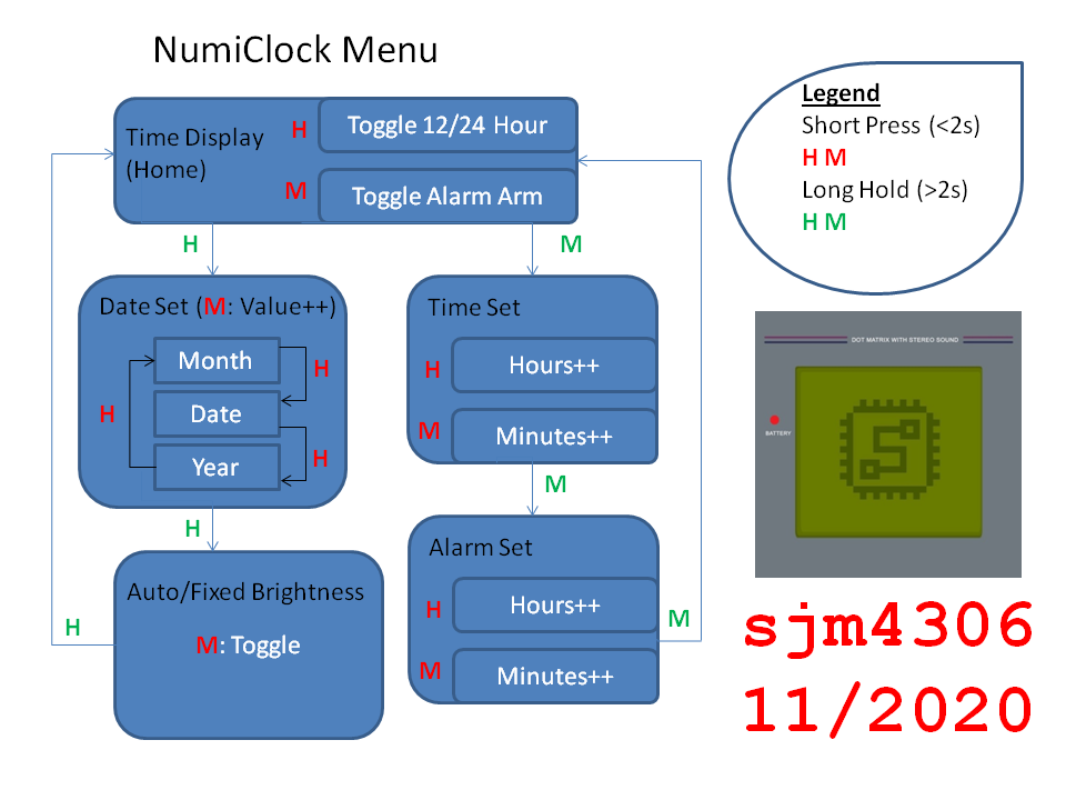
The final (but probably most important) part of this project was developing the user interface, which is made more difficult by the design choice of only having 6 seven segment digits, 4 colons, and only two physical buttons. I first drew out a pseudo flow chart with what I thought would be a reasonable interface.
Yeah I already know this flow chart breaks from convention, but I think it gets the point across without taking up too much space.
![]()
![]()
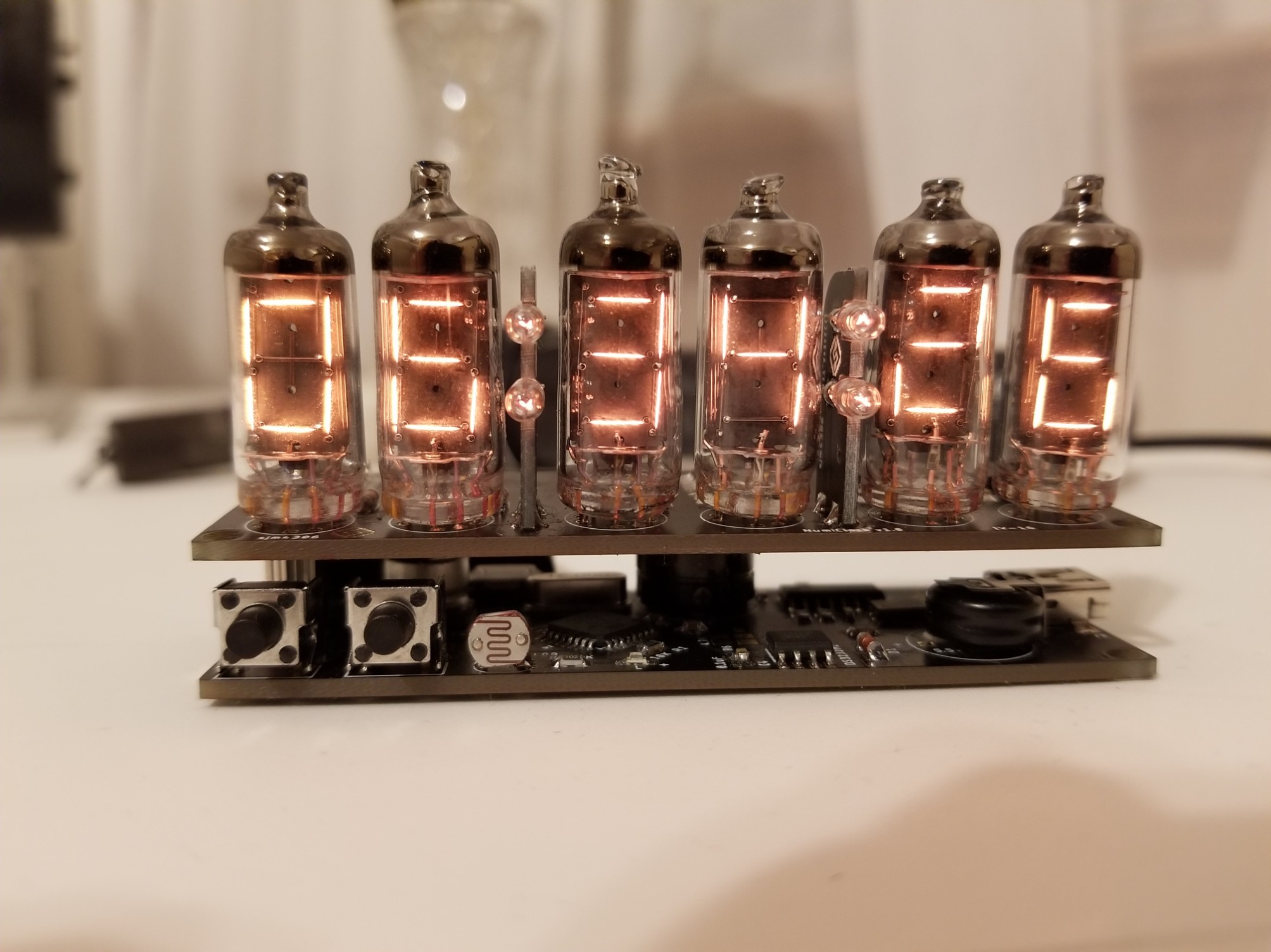
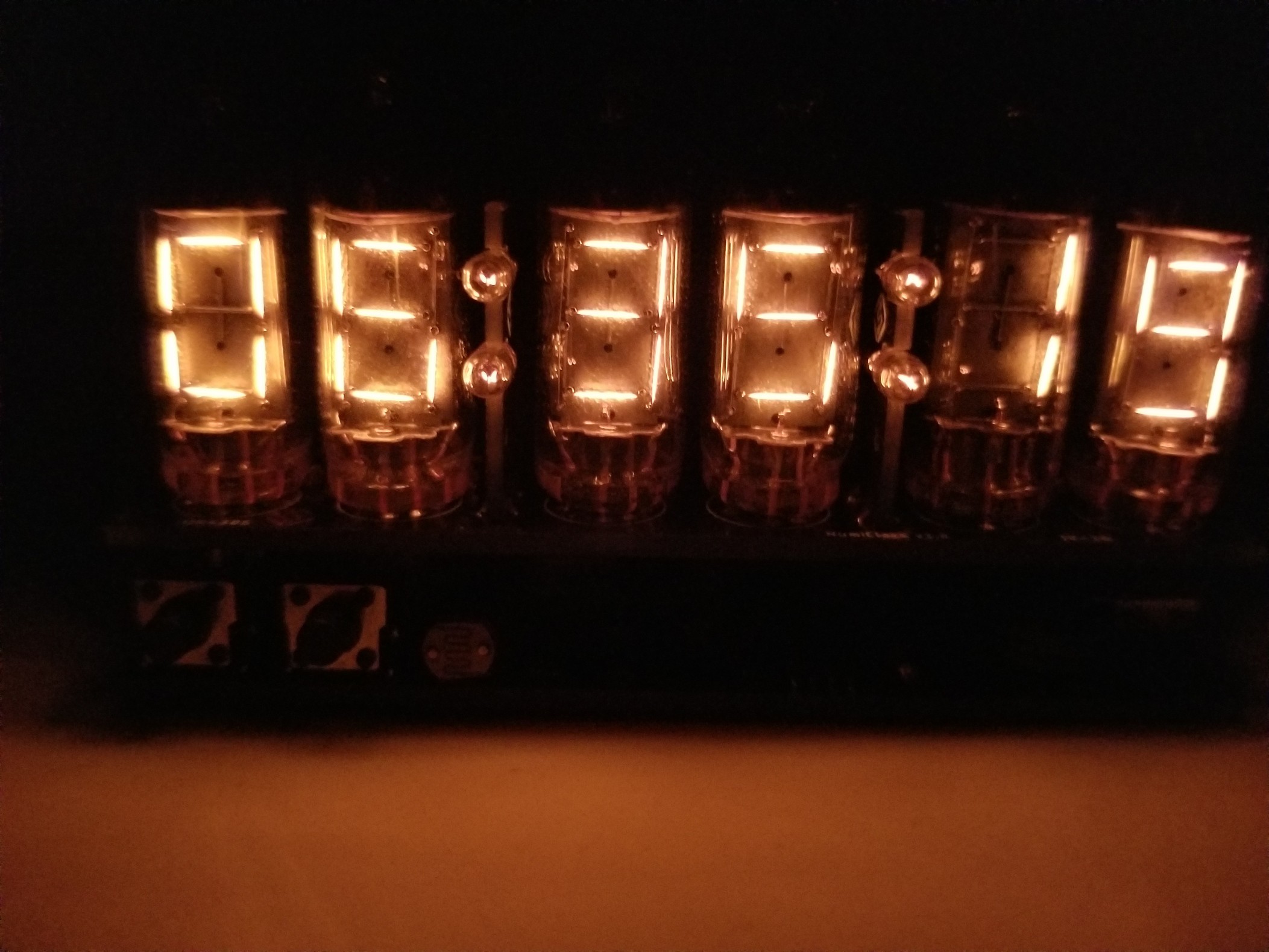
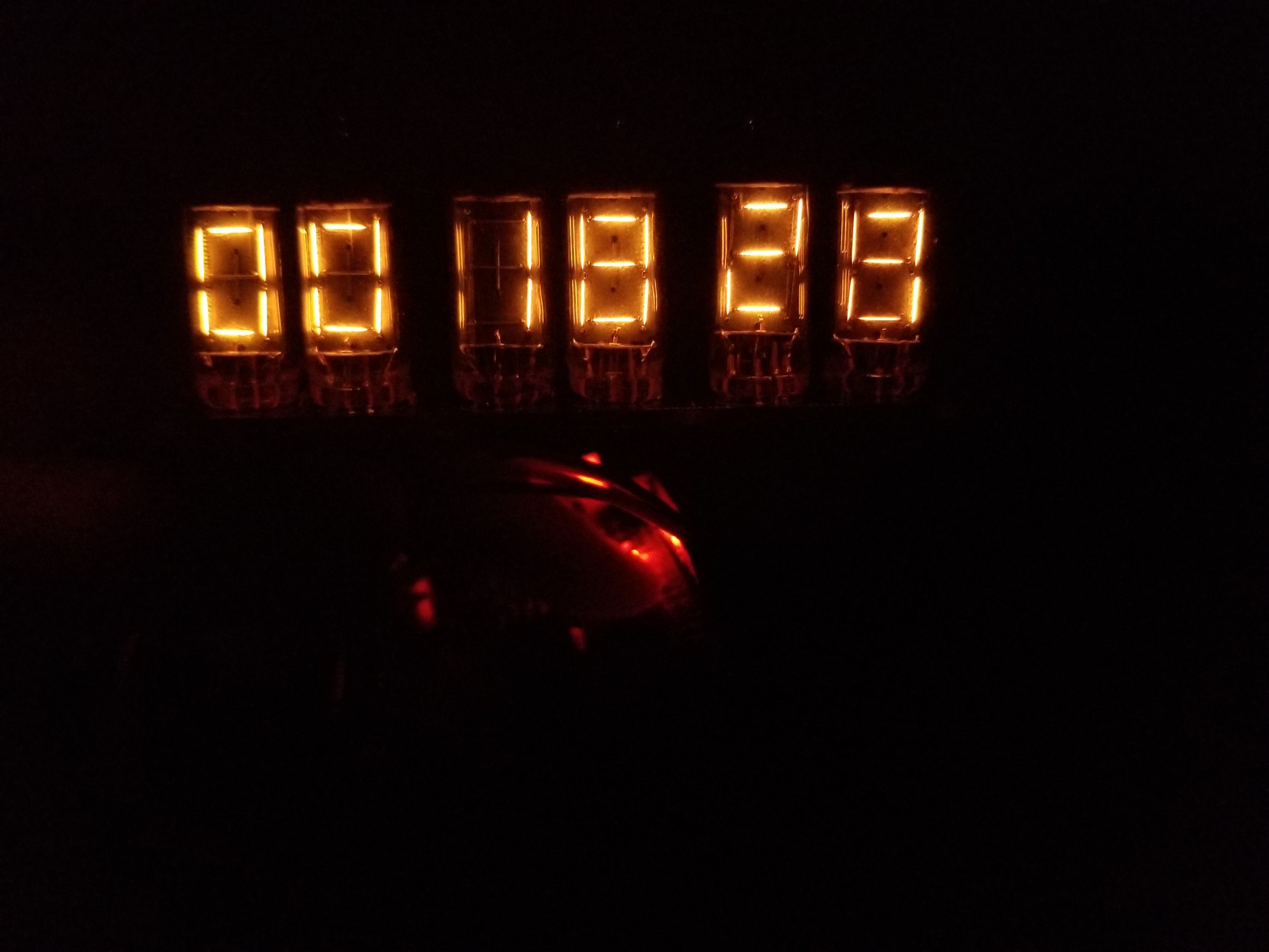
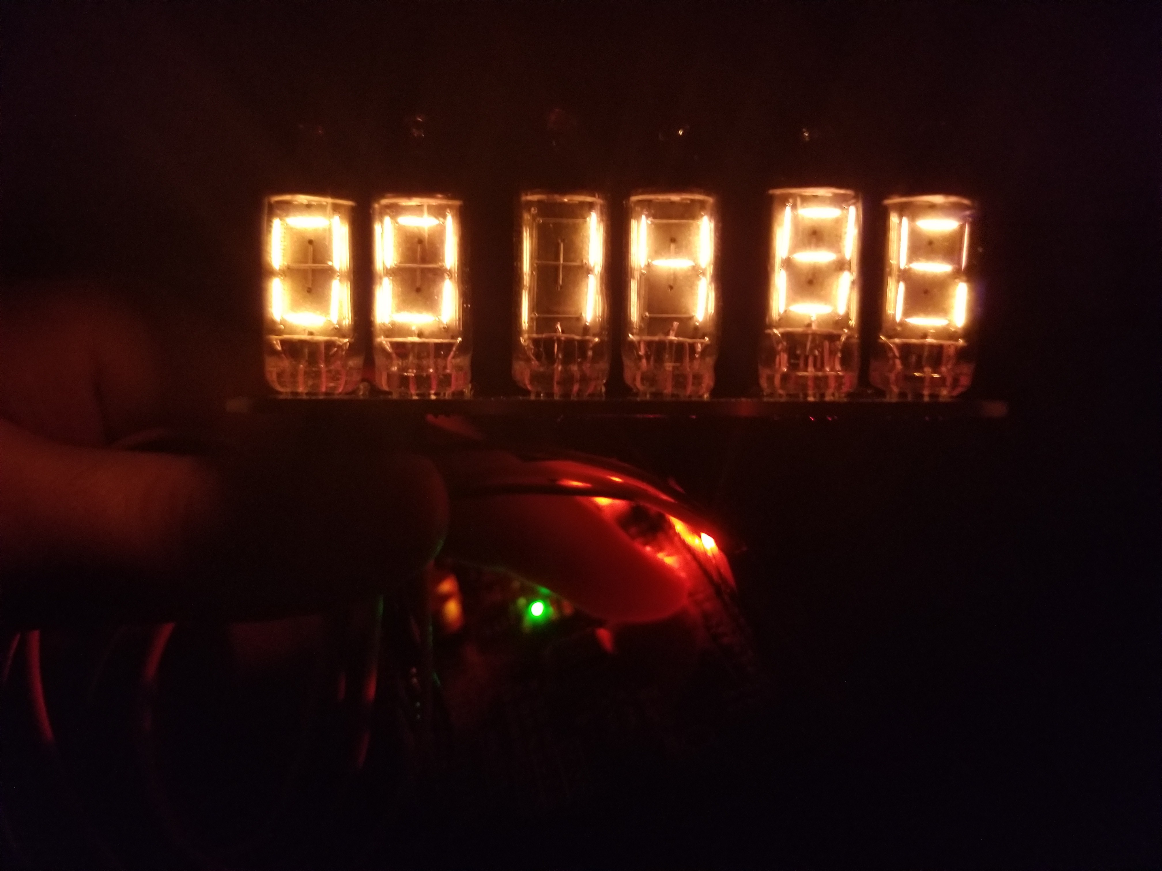
Here's some eye candy of the Numiclock!
So that's the current progress as it stands. I'm still hunting some bugs and thinking if I want to add any additional features (gotta be careful of feature creep though). In the next log I'll shoot a video of the clock in operation with a demo of the interface and controlling over usb.
-
Driving the Tubes (with SPI)!
09/06/2020 at 21:01 • 0 commentsTo start off, thanks to the video sponsor: JLCPCB for sponsoring this project. JLCPCB Prototype for $2 (Any Color): https://jlcpcb.com
My IV-16 Numitron Tubes took a little while to arrive from Europe but now that they are here I've designed a little board to hold them along with the circuity necessary to drive them. All tubes are driven unmultiplexed with each having their own 74HC595 serial shift register so all six tubes can be controlled with only 4 pins (one of them being a pwm brightness control). In this video we take a look at the display boards I just received fresh from JLCPCB, assembly them, program some test code to drive the tubes with a simple counter demo, and look at the final display board running. In the next video we will design, assemble, program and test the additional vertical colon boards as well as the main bluetooth clock board. Stay tuned to see the final clock!
![]()
![]()
IV-16 NumiClock
I love vintage display technologies and building clocks so naturally the IV-16 Numitrons are perfect!
 sjm4306