Extract the RS540 12V DC Motor from the portable air compressor and print its case using Ender 3 or another 3D Printer. The file is
provided here.
Attach the Dremel Chuck to the end of the motor axis. It's also possible to don't use a chuck by printing the drill bit threaded holder (file provided). If you don't use a chuck, put a small piece of soft rubber on the outside of the PCB drill bit to keep it from "dancing" inside the holder metal tube.
Glue a 3.5" HDD magnet to the outer wall of the 3D Printed Motor Case
Remove the Ender 3 Extruder head and attach a 90° steel angle large enough to hold the drill attachment. I don't have pitctures, sorry, but it's shown in the demo videos. Don't forget to screw the extruder head again.
2
The Drill Attachment Wiring
We are going to use the Ender 3 Extruder Cooling Fan to control the drilling motor. Cut the wire close to the extruder head. I use a simple switch (a DPDT one will do) to enable or disable the motor control. A resistive voltage divider is used to lower the Ender 3 Fan voltage from 24V to 10V.
Glue the IRF3205 (with the gate-source resistor) to the motor case (it won't usually heat enough to justify a heatsink). A detailed schematic is shown below:
3. To power the drill, use a regular computer 12V PSU. My drill attachment has 2 plugs: one for power (goes to the PSU) and another for switching (goes to the ender 3 fan)
3
Drilling Part I
Place the PCB to be drilled on top of a cardboard sheet (it doesn't need to be thick, mine is 1mm), which goes on top of the Ender 3 printing table. Hold everything with clamps on the corners. Alternatively, you might use double-sided stick tape.
Manually position the drill (and the drill head) over the point you wish to set as the (0,0) (X,Y) point. The drill should just barely touch the board and shouldn't scracth the copper when it is moved.
4
Drilling Part II
This will depend on the software you use. This is the workflow for KiCAD 5:
On KiCad, create an auxiliary axis and set it anywhere you desire. Keep in mind this will be the same (0,0) (X,Y) point where you positioned the actual drill.
Go to Plot, Generate Drill File, Use Auxilliary Axis as Origin, generate Drill File.
On FlatCAM (tested with 8.991 beta):
Before anything else go to File, Backup, Import Preferences from File and load the preferences provided here.
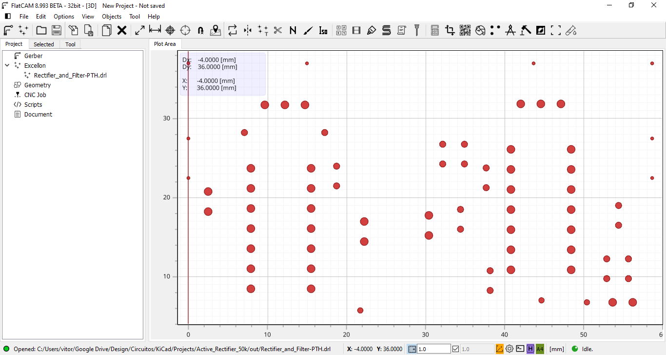
Go to File, Open, Open Excellon and select the KiCAD PTH file. Ypu will see something lik this:
2. Click on your excellon .drl file under the Project tab, then click on the Selected tab, choose marlin as the preprocessor and click on Generate CNCJob.
3. Under Prepend to CNC Code, add:
G92 X0 Y0 Z0
M106 S200
4. Under Append to CNC Code, add:
M107
M84
5. Click on Save CNC Code.
5
Drilling Part III
Click on the generated .gcode file, drag it and drop it on the provided Marlin Excellon Fix F100 Z.exe. This will patch the generated to G-Code to move the drill in the XY plane at F100 speed. As of FlatCAM 8.991 beta, it locks the XY speed to F3.0 without the fix.
Now, everything should be ready. Just upload or copy the G-Code File to Ender 3 and hit print. I use Octoprint to allow remote printing.
 Vítor Barbosa

Discussions
Become a Hackaday.io Member
Create an account to leave a comment. Already have an account? Log In.