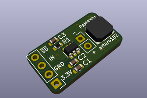
Saw someone selling a two tone buzzer on Aliexpress for $10. Immediately my brain said, are you serious?
Just by investing a little bit of your time and enthusiasm you can make this circuit for under 3 dollars.
Components Used
---------------------
For this project we need:
- 1 x 555 Timer IC
- 1 x Pushbutton Switch
- 2 x 1N4148 Diodes
- 1 x 10μF Capacitor
- 2 x Ceramic Capacitors (103)
- 4 x 47K Resistors
- 1 x 8Ω Speaker
So, this is the simple schematic of the two tone buzzer circuit using the 555 timer IC.
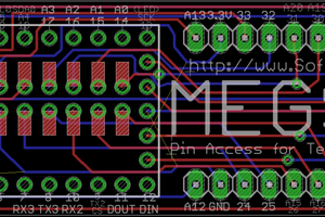
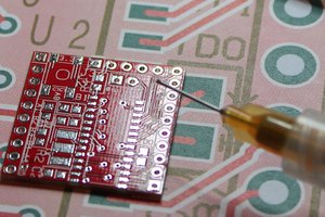
And, this is how my board looks like.
The link to the gerber file is here: http://scorphq.com/GrpHDD/GerberFiles/Gerber_Door_...
You can also download it from my website or my blog: http://diy-projects4u.blogspot.com/
Lets start the project by soldering the 4, 47K resistors to the board. Then, lets solder the 2, 1N4148 Diodes to the board. After that I am soldering the 2 ceramic capacitors to the board. Next, I am soldering the 10μF Capacitor followed by the base of the 555 timer IC. Finally, I am soldering the male female pin-headers to the board. It really doesn't matter what order you solder the components to the board; however, putting the small components first makes the process a bit easy.
Once all the components are in place its time to install the IC to the base, that's it all done.
By pressing the push button switch you can now produce the two tones from the 8Ω Speaker attached to the pin headers.
Thanks
----------
Thanks again for checking my post. I hope it helps you.
If you want to support me subscribe to my YouTube Channel: https://www.youtube.com/user/tarantula3
Video:
Full Blog Post: https://diy-projects4u.blogspot.com/2020/09/two-tone-doorbell-using-ic-555.html
Gerber File: http://scorphq.com/GrpHDD/GerberFiles/Gerber_Door_Bell_V1.zip
BTC: 35ciN1Z49Y1bReX2U7Etd9hGPWzzzk8TzF
DOGE: DDe7Fws24zf7acZevoT8uERnmisiHwR5st
LTC: MQFkVkWimYngMwp5SMuSbMP4ADStjysstm
ETH: 0x939aa4e13ecb4b46663c8017986abc0d204cde60
BAT: 0x939aa4e13ecb4b46663c8017986abc0d204cde60
Thanks, ca again in my next tutorial.
 Hulk
Hulk


 arturo182
 T. B. Trzepacz
 Torbjörn Lindholm