 mlos
mlos-
1LED Control Module
Behaviour
The LED Control Module (LCM) drives an RGB LED using different colors and blinking patterns indicating the system state.
- Green blinking: Starting. This state is displayed until Volumio is completely operational.
- Green steady: Started. Normal operation.
- Red blinking: Stopping.
- Red slow blinking: Stopped. Indicates that the system can be powered off. Turning off the Pi during normal operation is not recommended, and it cannot be powered off completely using software.
![]()
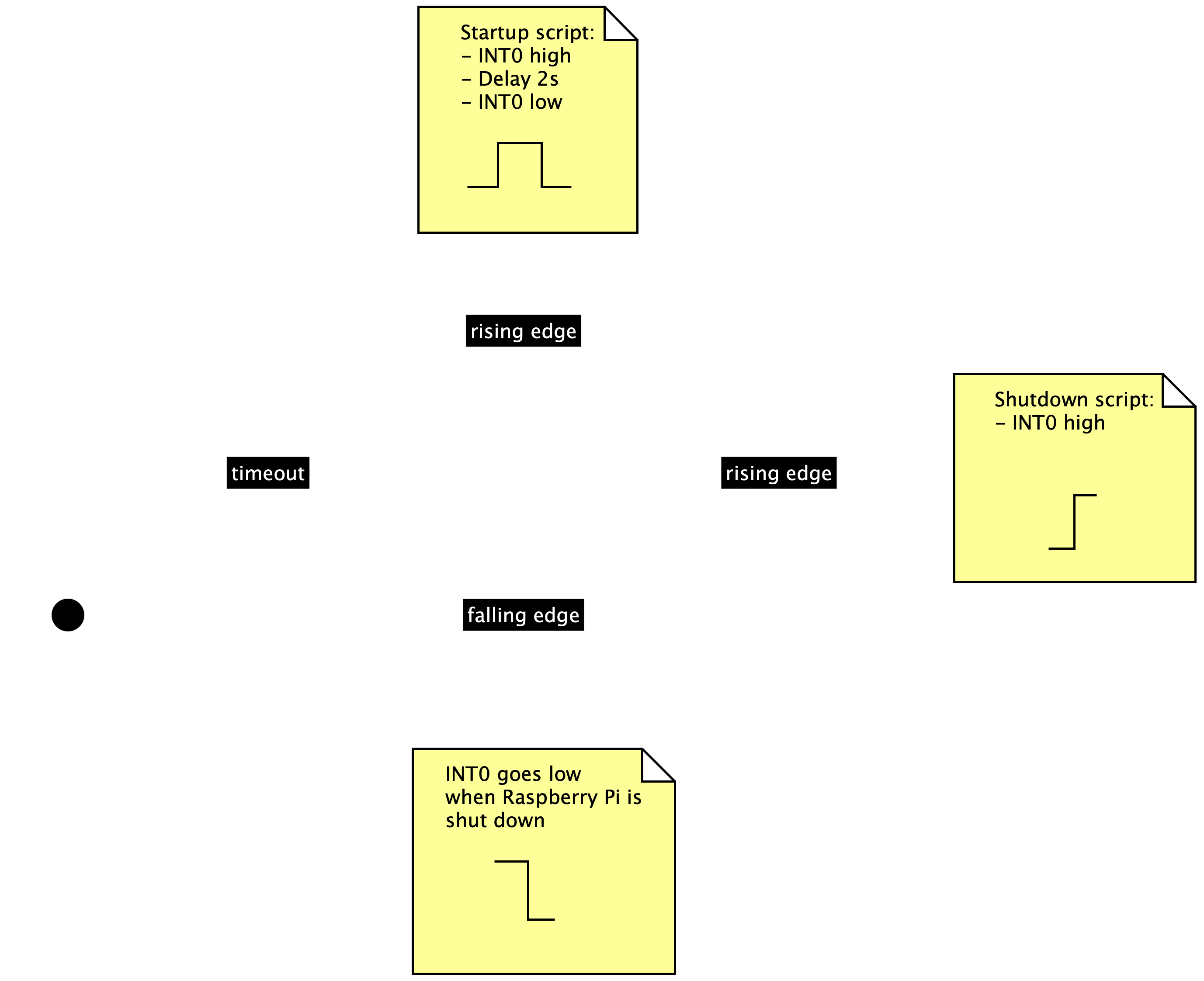
The state diagram (done with yEd) shows the different state transitions.Implementation
The LCM is implemented using an ATTiny85 microcontroller listening to level transitions on the a GPIO pin on the Pi, and driving an RGB LED according to the above state diagram.
The GPIO pin on the Pi is controlled by regular startup and shutdown scripts that have to be installed after installing Volumio. The pinout is described in the Prototype step.
Hardware
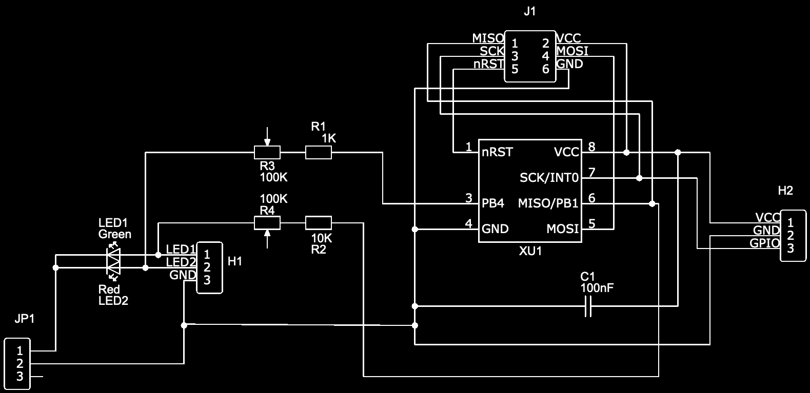
The circuit (drawn using EasyEDA) consists of the following main components.
- A six-way AVR ISP header (J1).
- Input header, including the GPIO connection from the Pi (H2).
- Output header, for connecting the LEDs (H1).
- The LEDs will only work when pins 1 and 2 of JP1 are shorted. Otherwise pins 1 and 2 of H1 can be used for an alternative connection. Used for debugging.
- The resistors R1 and R2 are used to reduce the basic brightness of the LEDS.
- Potmeters R3 and R4 can be used to further tune the brightness.
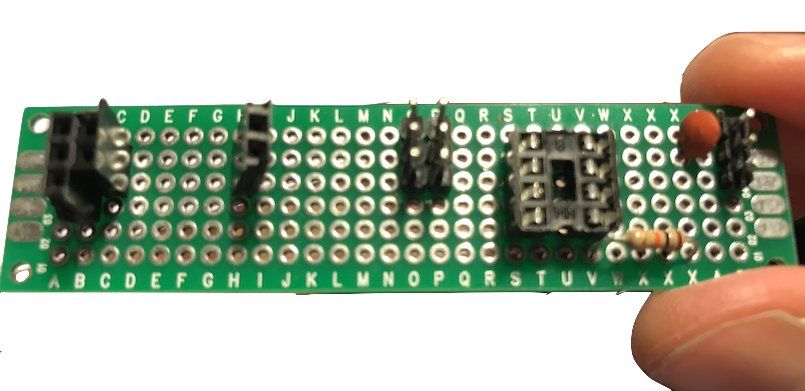
The hardware components (not yet mounted in the picture) are mounted using through hole soldering on a simple PCB.
![]()
Software
The LCM firmware can be found on GitLab. The code is fully documented. From a high level perspective, it implements the state machine depicted above and uses (low frequency) PWM to blink the LEDs according to the current state.
The software was developed on a Mac using the GNU AVR toolchain. Conveniently, the toolchain comes installed with the Arduino IDE.
The Arduino was used as a programmer, with the ATTiny being the target, connected through the P1 header on the PCB.
-
2Install Volumio and scripts
NOTE: some familiarity with Volumio is assumed. If you are not familiar, their Quick Start User Guide may be helpful.
Install Volumio
Download Volumio, and install it on a micro SD Card. A minimum of a 4GB is required, 8 GB is recommended.
Check the Raspberry Pi Foundation's website for some useful guides on how to write an image file onto an SD card using your favourite OS.
Install Scripts
Boot into Volumio, and make sure you can access it over SSH.
Follow the instructions from the GitLab project. The GPIO pin can be changed in the startup script.
-
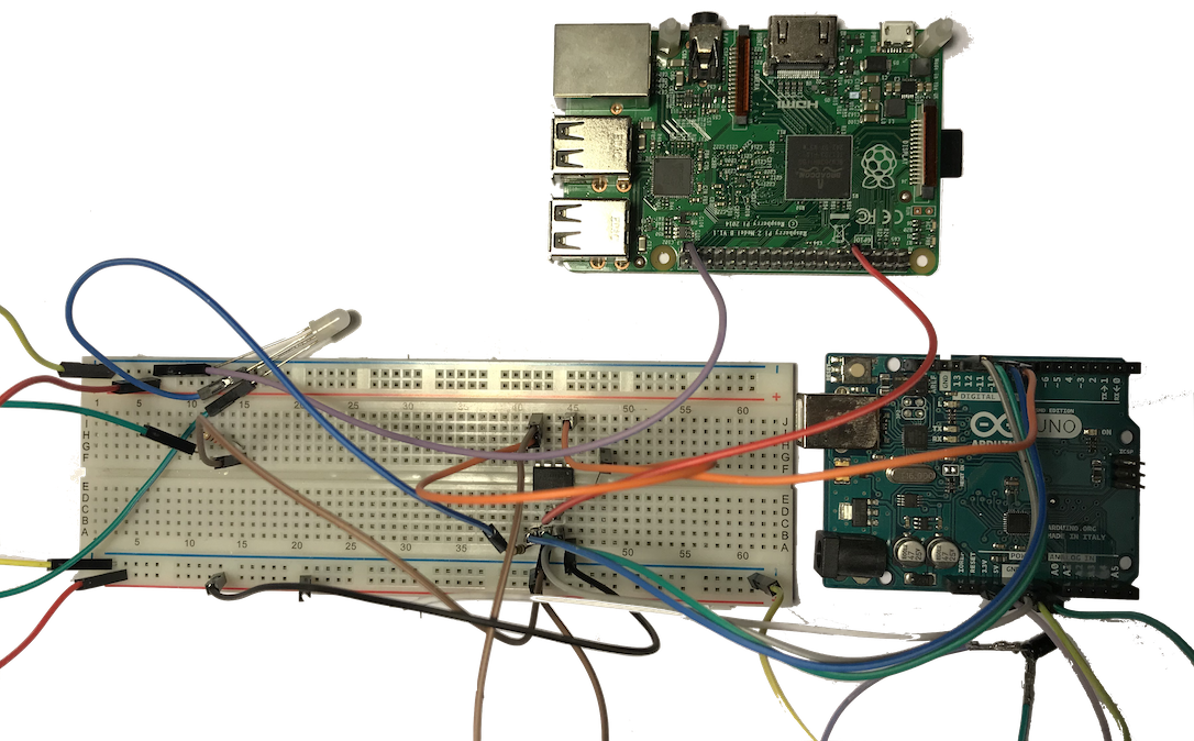
3Prototype
Now it's time to put together a prototype, to see if the hardware and software.
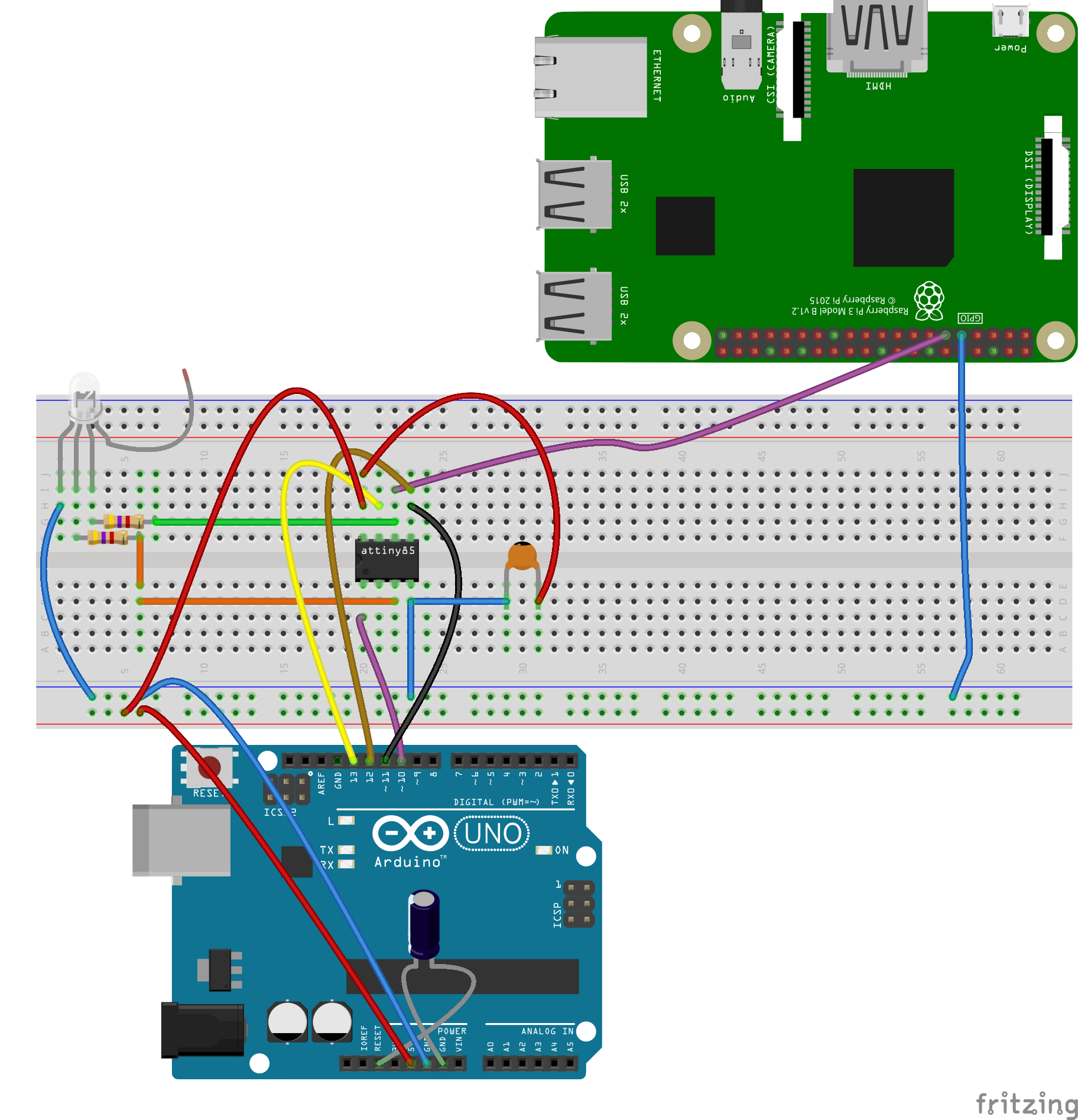
The diagram (created using Fritzing) shows the system as it becomes one step closer to the real hardware.
![]()
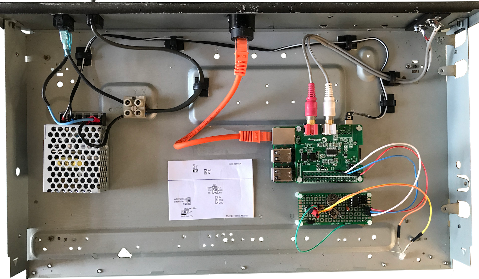
And now with the real hardware (spot the differences...):
![]()
On the Pi, GPIO 17 was chosen as the LCM GPIO-in (eventually connected to INT0 on the ATTiny) because this pin goes to low when Pi is shut down. It can be changed to another pin as long as it behaves as GPIO 17 and does not conflict with the pins specified by HiFiBerry.
-
4Casing
It's time to build the case. For this, I disassembled the CD player enclosure and prepared the separate parts.
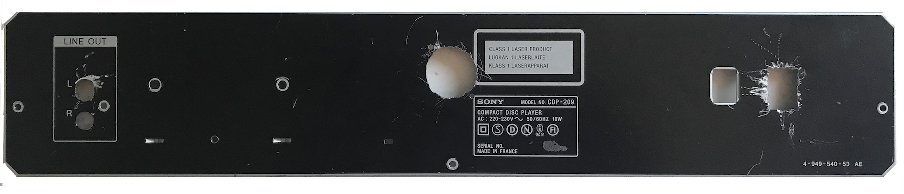
The back panel
Let's start with the back panel. Drilling some holes - tools available: a hand drill.
![]()
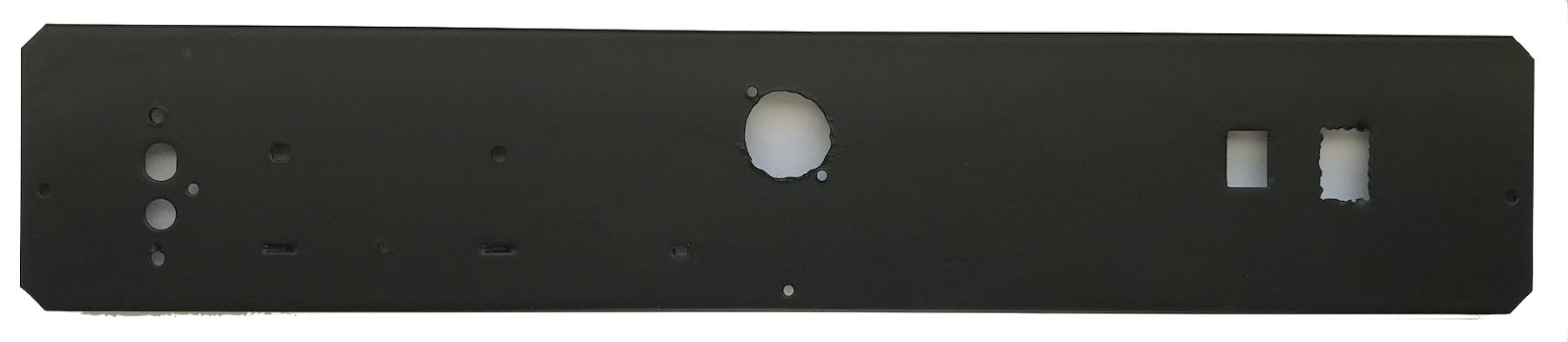
Once all is drilled out, it looked like this.
![]()
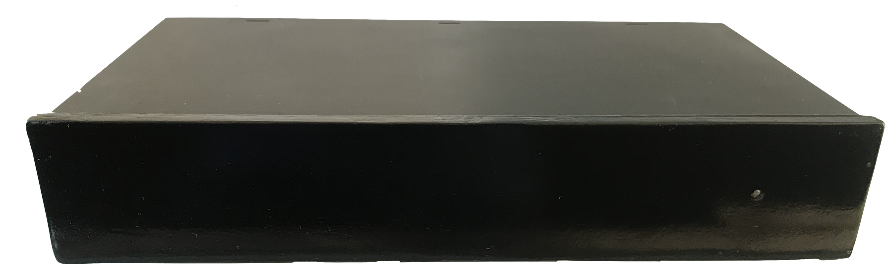
After a paint job.
![]()
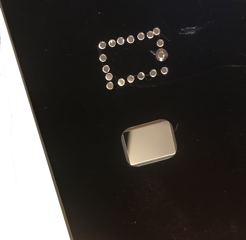
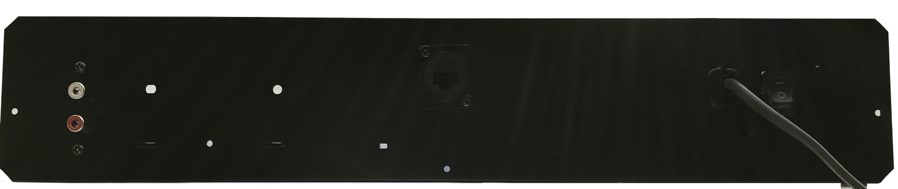
Inserting panel mounted components.
![]()
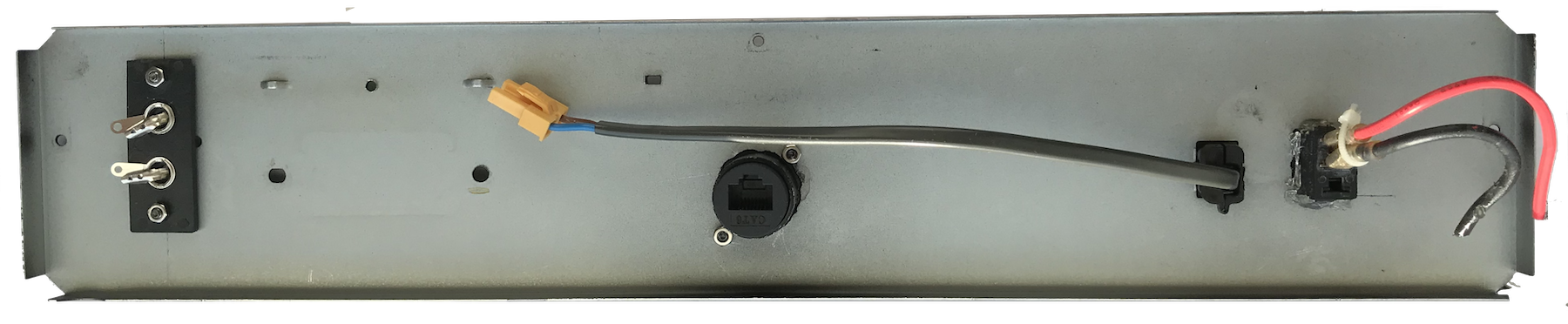
The inside
![]() The Front Panel
The Front PanelMade from a piece of wood and many layers of spray paint. The result is still rough and not as smooth as I had hoped. For now, it will do.
![]()
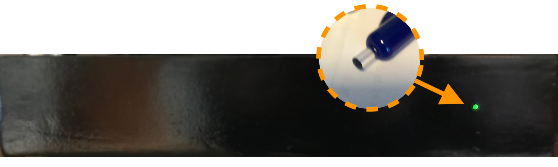
The cap of a Bic pen serves as a light pipe.
![]()
Putting in the components.
With the help of various spacers and guides I mounted the pieces of hardware. The LED was fixed to the front panel "light pipe" at a later stage (not shown).
![]()
Tadaa
![]()
-
5Retrospective
No project is complete without a retrospective. Here we go:
The good
- It just sounds great, at least in my opinion. I'm using lossless audio (Flac).
- An existing HiFi casing provides an excellent project box.
- Panel mounted components help hiding ugly hand drilled holes.
The bad
- No on-device playback control. Always needs a Web interface. Admittedly both Desktop and mobile interface looks pretty good, but sometimes you just want to interact with the player itself.
- After a software update, the scripts driving the LED module need to be re-installed.
- I may need to write another script for that integrates with the update mechanism to solve this problem.
The ugly
It is not easy to get a smooth, professionally looking front panel - either you use good tooling (don't have that at hand) or have it made somewhere.
Both options exceed the magic $100 dollar limit as of which it becomes more interesting to just buy a media player instead. But that takes away the DIY-fun, so ...
... the next
Here are some ideas for Nemo 3.
- Spend some extra $$$ on a anodised alumunium front panel and/or professional casing.
- Touch screen interface.
- Check out a DAC with a different chip, e.g. the ESS9023 in the Audiophonics Sabre (the HiFiBerry has a PCM-5122).
 The Front Panel
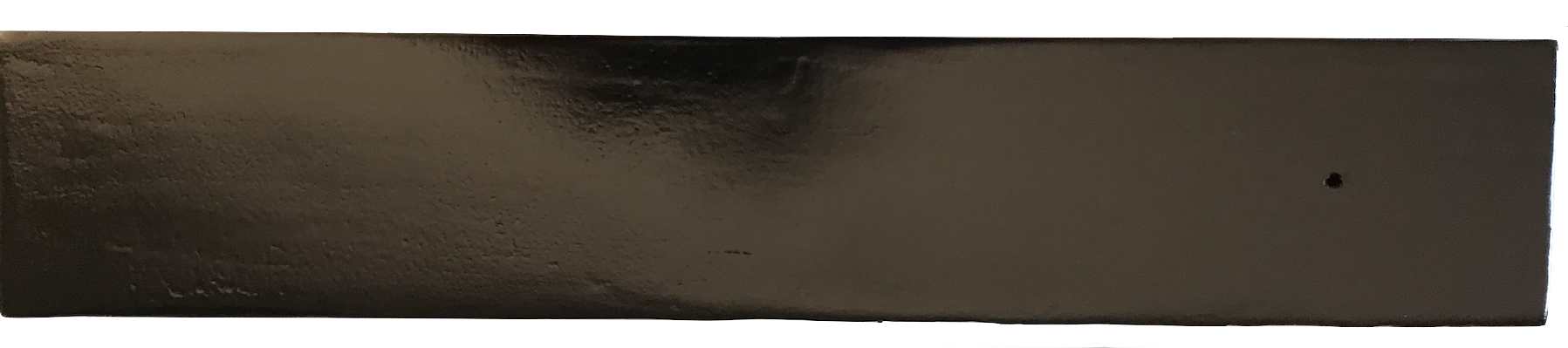
Discussions
Become a Hackaday.io Member
Create an account to leave a comment. Already have an account? Log In.