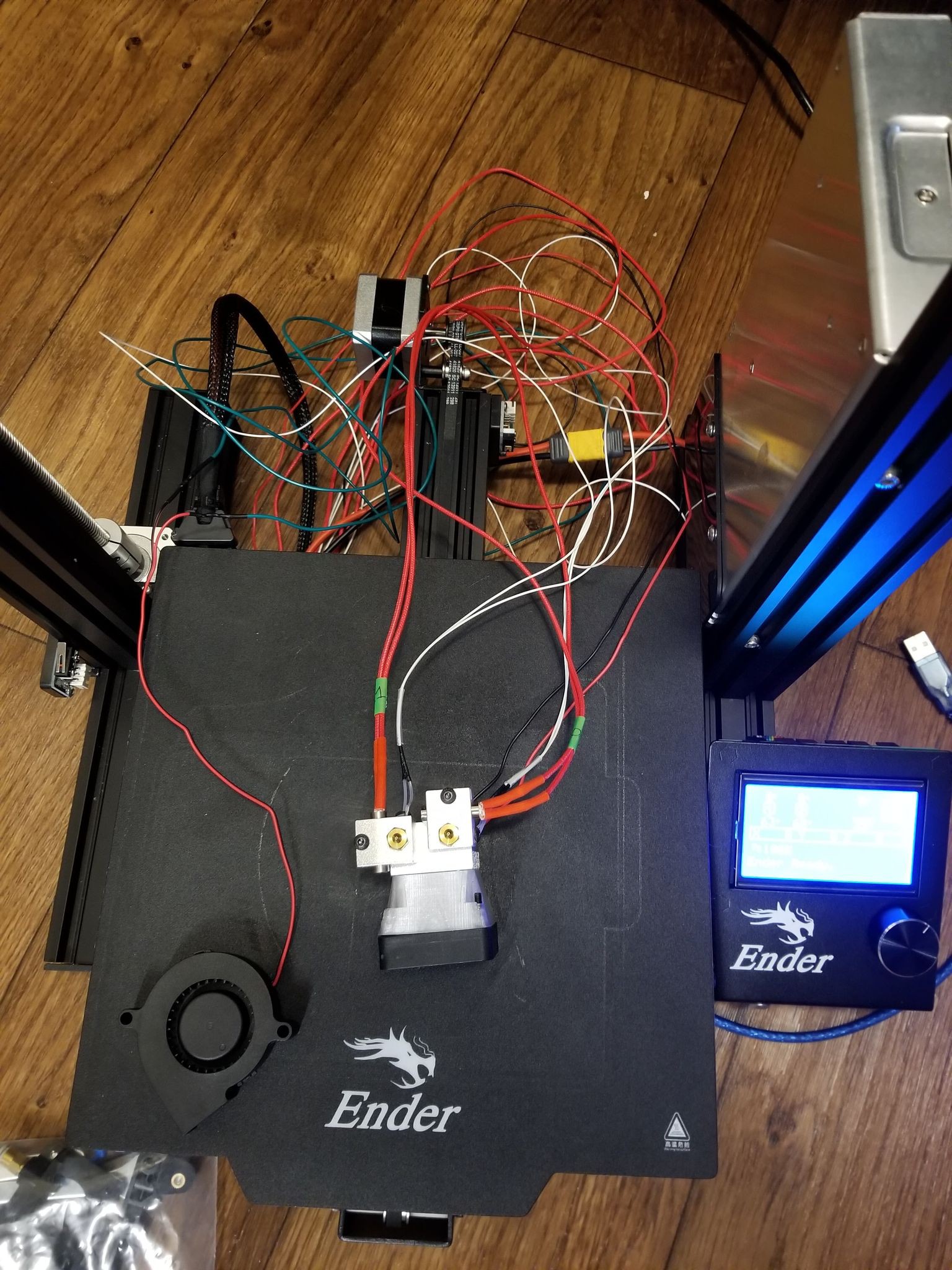
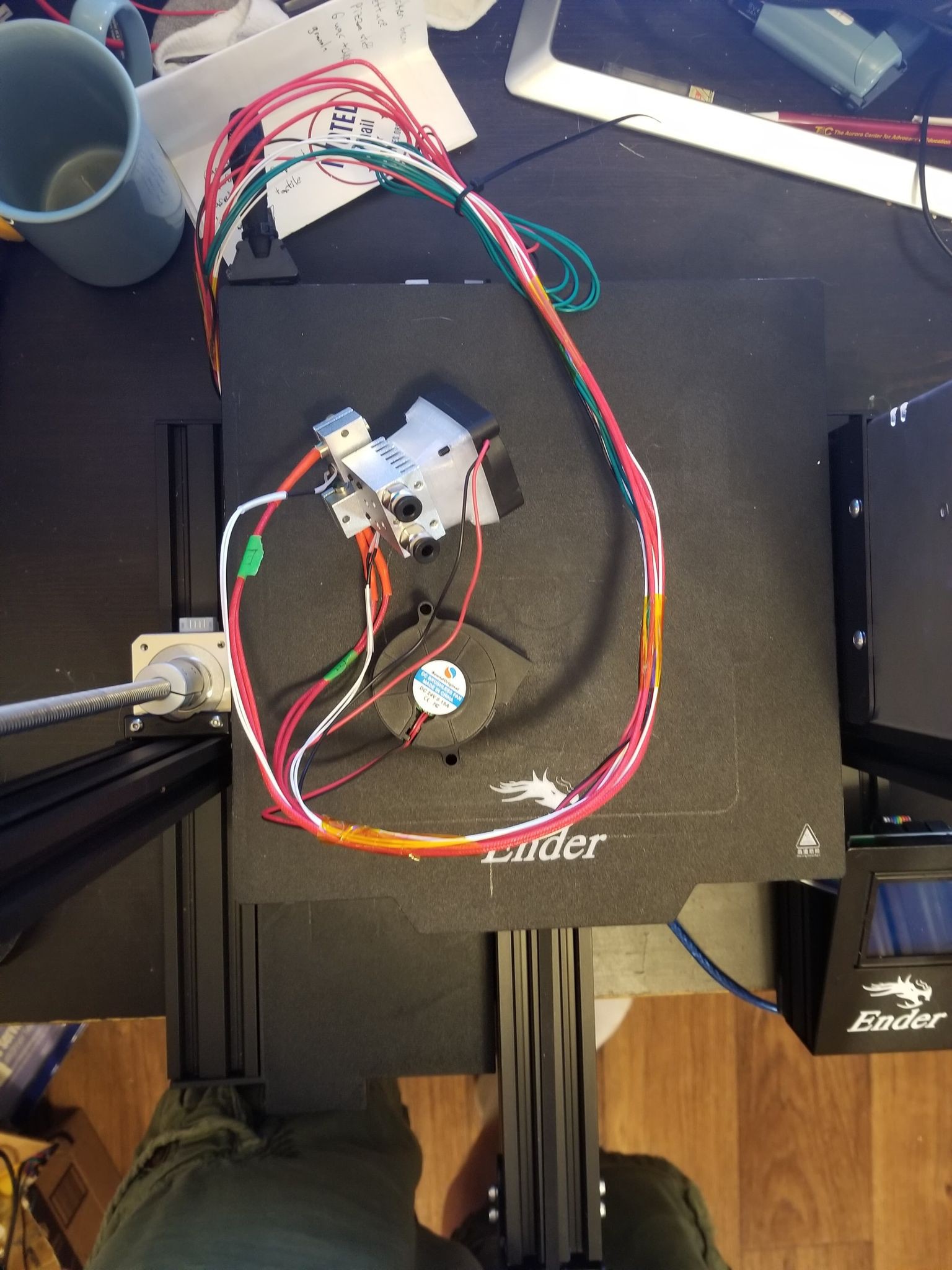
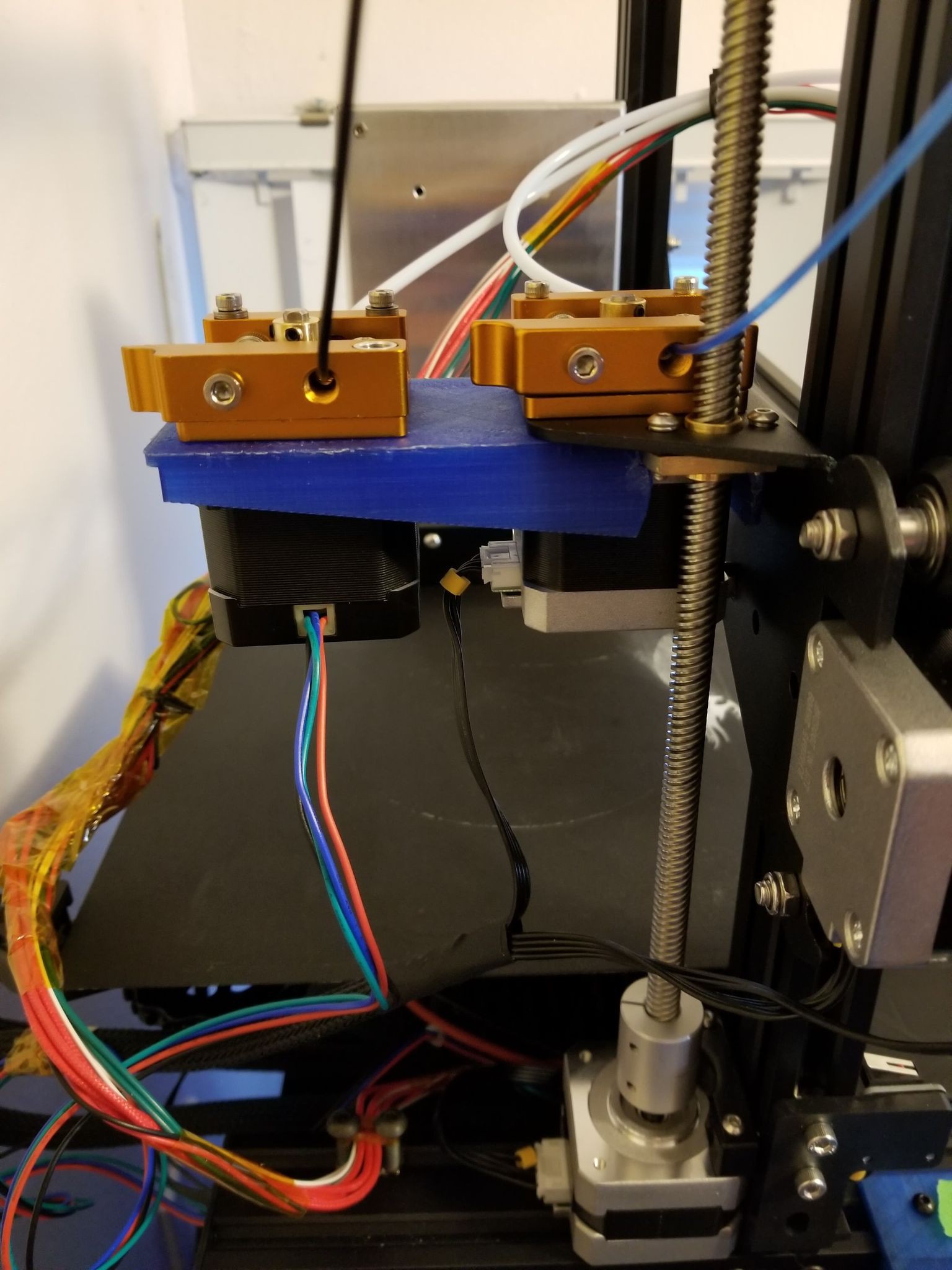
Thermistors held in by washers now. Socks on the heater blocks. It took a bit of finagling to get the wires in comfortable positions, you can see below how I managed it by turning the left nozzle 90°, and routing the heater/thermistor/fan wires over the top of the x-rail.
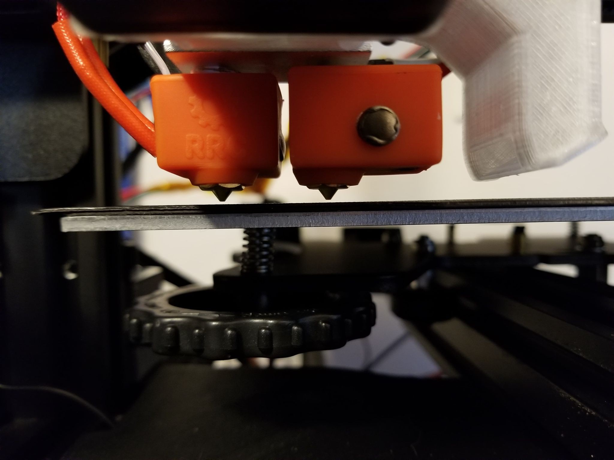
The hardest part of installing the hotend was probably getting the two nozzles as level as possible. After greasing the throats and inserting them in the heat sink I just eyeballed their height's, and ended up with what I think is good enough.
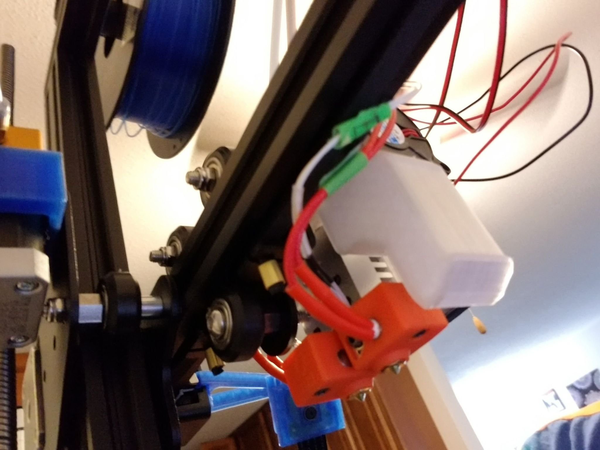
Finally was able to mount both steppers with their extruder frames. It might be worth getting a more powerful stepper for the z-axis eventually, as it has substantially more weight now.
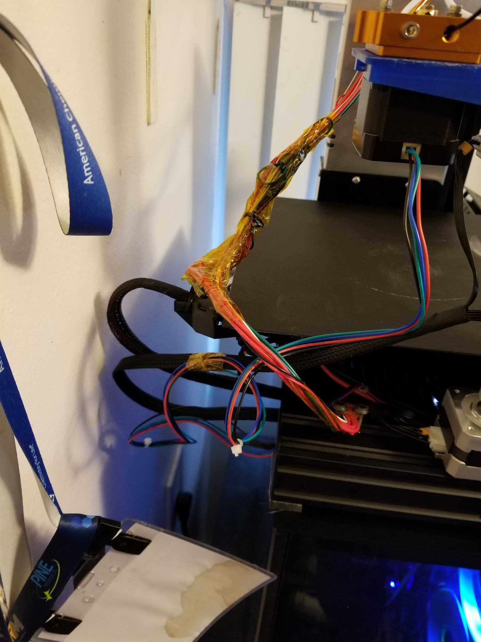
Very poor cabling again, I just wrapped all the wires to the hot end with polyimide tape, and used a couple screws/t-nuts with a loop of tape around them to hold the cable out to the side so the y-stage wouldn't catch it.
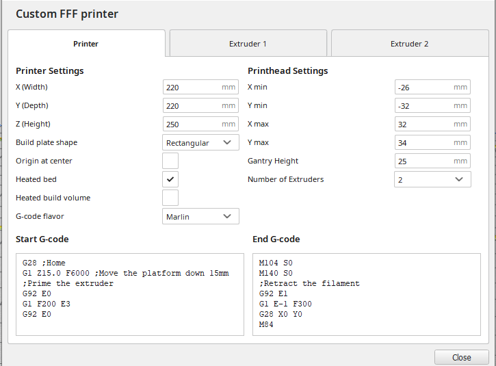
the full printer is shown belowYou'll need a custom printer profile in cura, I just copied the X/Y min/max settings from the Ender 3 Pro profile. There are nozzle offsets you can play with in the extruder tabs, but I haven't messed with those values yet.
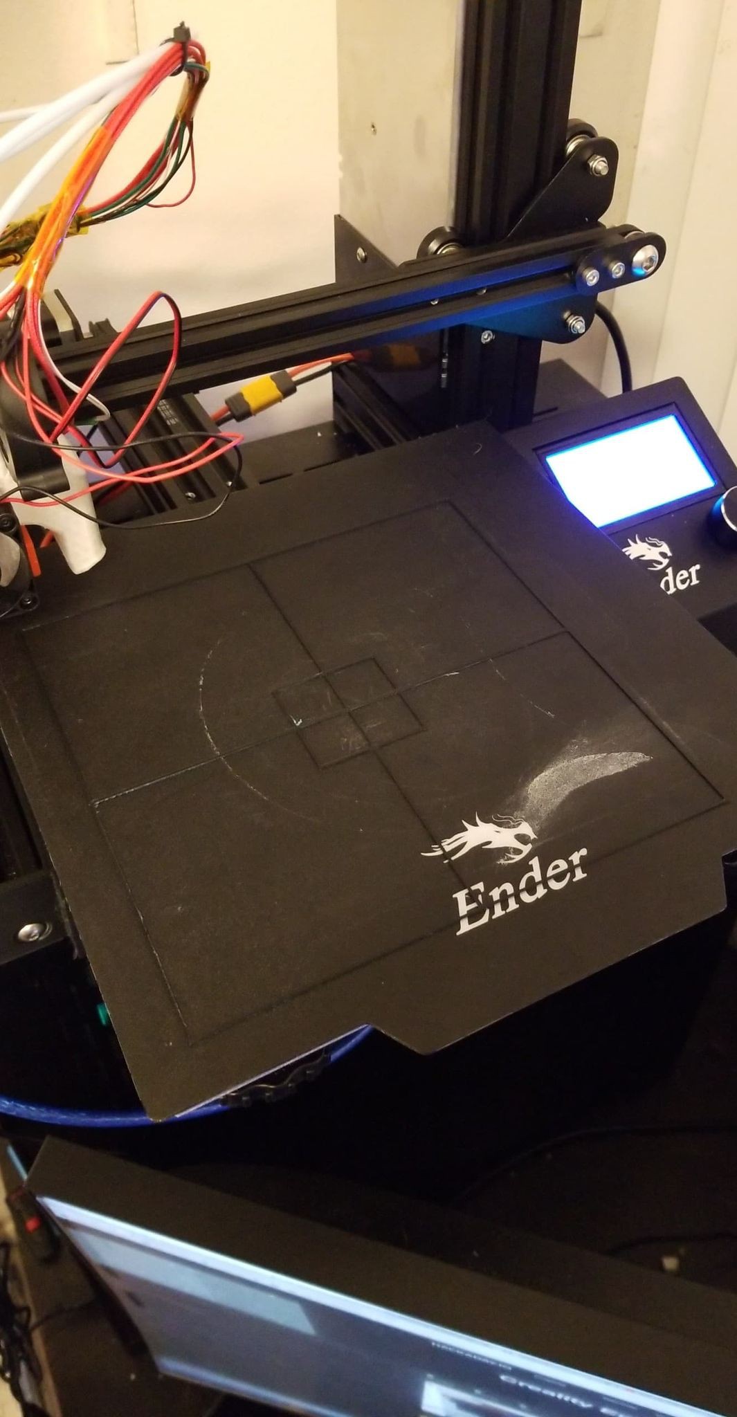
After manually leveling the bed, I fired up the first dual print to check the accuracy of the nozzle offsets in the firmware (which is just 18mm x-offset for nozzle 2). I was pretty surprised actually, but the offset in the firmware took care of aligning the nozzles during printing pretty well. The print isn't centered on the buildplate, but that should be a pretty easy fix either somewhere in the firmware or in the cura profile.
I printed the first two layers with translucent blue PLA from nozzle 1 and the next 2 layers with black PLA from nozzle 2.
Top of print:
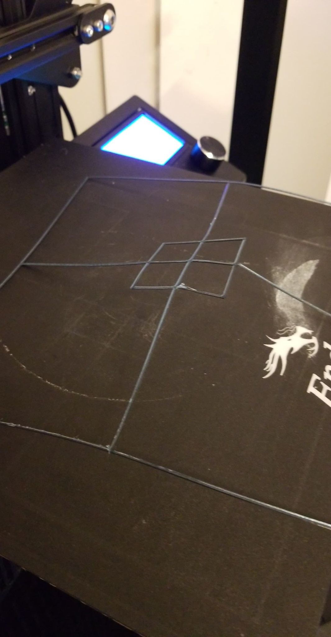
Bottom of print:
I'll have to do a bit more finessing to get the X/Y offset just right, it looks like there might be ~100µm or so misalignment, but the nozzle heights were level enough that they didn't damage each other's extrusions.
So yea, not sure if I'll post any more updates, from here on out I think it'll just be pretty vanilla PID and stepper calibrations as well as tuning the nozzle offsets.
still waiting on the longer machine screws/washers/thermal grease, so I can't finish up the hotend or mount the second extruder stepper yet.
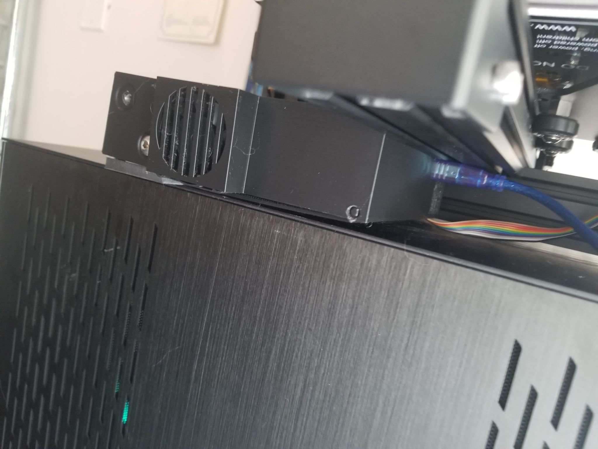
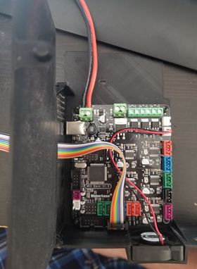
I found a slight issue with the motherboard enclosure, the USB port position causes the Y-axis rail to slightly conflict with any USB connector plugged to the board. Only using one screw to fix the enclosure to the printer allows the enclosure to rotate enough to take the strain off of the USB connector port. Revisions of the motherboard enclosure should probably use taller standoffs to move the USB port a bit further from the rail, but at this point I'm not going to worry about it.
I got the crimp connecter kit which allowed me to interface the thermistors with the motherboard and start testing the hotend components. Was able to perform the hot tightening of both nozzles, they both briefly produced some smoke but I think that's normal on first heat-up. After that I wired up the heatsink fan (to the remaining 12/24V connector on the motherboard) and the part cooling fan (to the 'fan' screw connector terminal on the motherboard), and the bed heater and thermistor, and taped up all the cables going to the hot end. My cable management could use some work but it'll do for now.
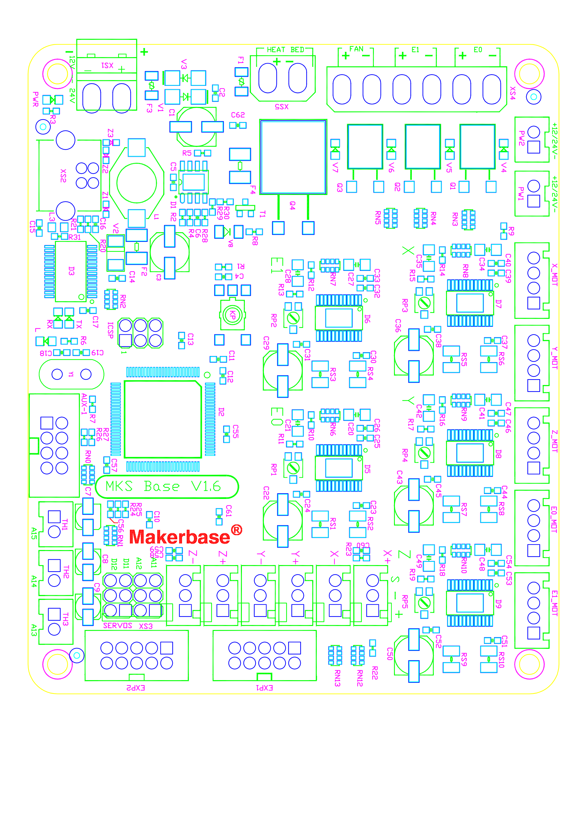
Quick note on thermistor placement: A13 is for E0 (nozzle 1) thermistor, A14 is the bed thermistor, and A15 is E1 (nozzle 2) thermistor.
Next I went ahead and wired up all the steppers to the board. For the endstops I had to cleave the original 2-pin connector mouldings (leaving the original crimp connectors on though) and refit them into 3-pin connectors to fit in the MKS Base. The MKS Base uses 5V pull-up resistors on the signal pin, so the wires going to the endstop switches needed to go to ground (-) and signal (s) with the 5v (+) pins left unused.
After plugging in all of the steppers and endstops to the motherboard, I reassembled the printer and booted it to test the stepper drivers. Fortunately all of the drivers worked, but the X, Y, Z, and E0 (original stepper the came with the printer) directions were all reversed. E1 (the new stepper) was rotating the proper direction, but I wasn't too sure about the connector orientation of it because it wasn't keyed like the others so I may have reversed the windings on that one. But either way just a quick firmware edit to flip the directions of the X/Y/Z/E0 motors (see configuration-rev3.h), and everything was going the right way
Big note: don't forget to adjust the z-endstop position, or you will run your hotend into the bed if it's already mounted to the x-carriage when you start homing.
After repositioning the z-endstop, axes homing went well, jogging all axes and both extruder steppers works. Pretty happy with the motherboard at this point. I don't want to jinx anything but it seems like all the components are functional.
At this point I've received all of the major components for this upgrade (motherboard, extra stepper, extruder frame blocks, hot end), and printed out all the needed mounting pieces.
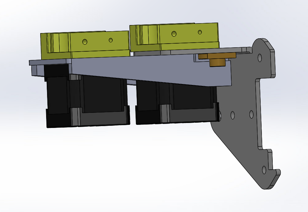
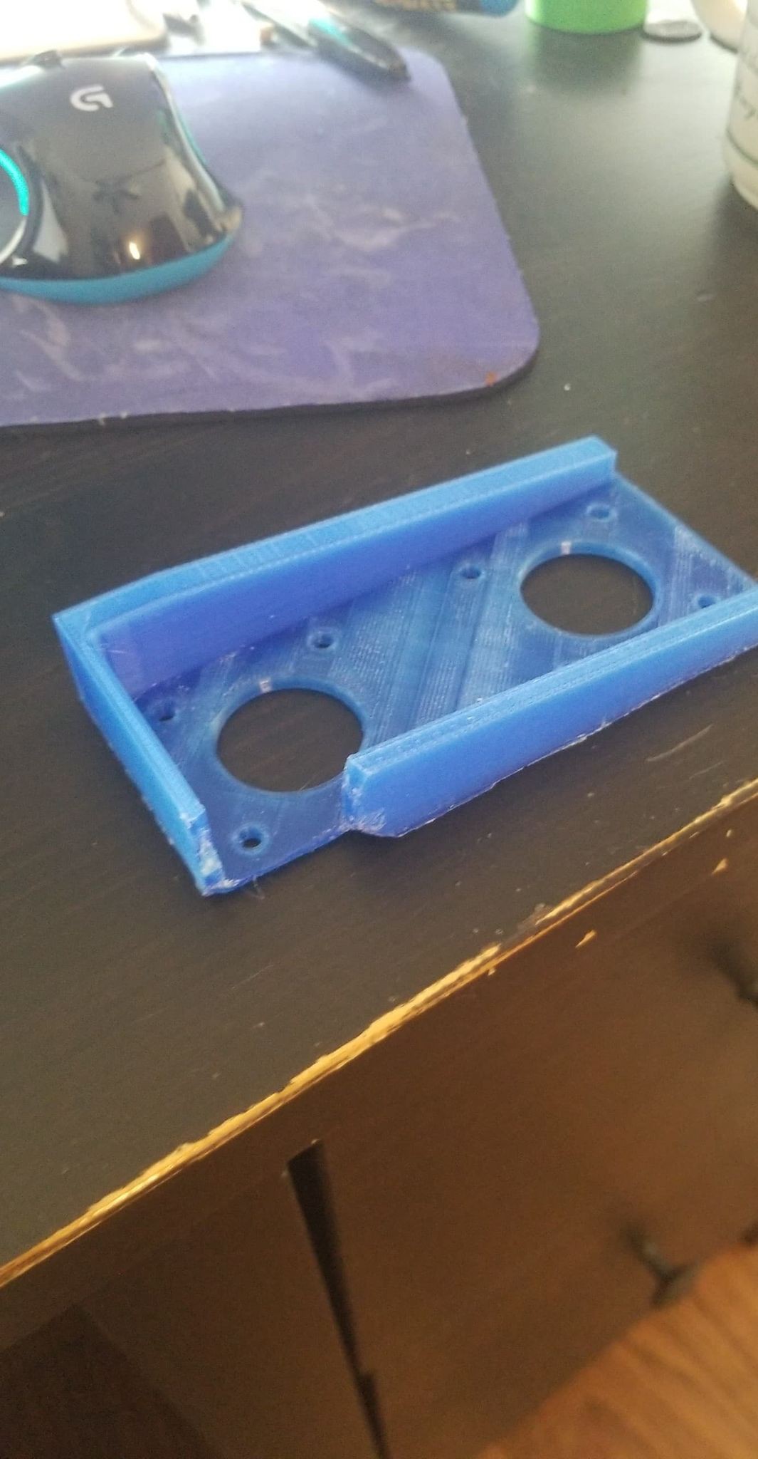
The only part I had to design from scratch was this mount for a second extruder stepper. I designed it to mount between the z-axis carriage and the first extruder stepper, with the mounting holes for the second stepper extending out to the side.
Based on the CAD model I thought I designed it with enough clearance for the lead-screw threaded piece, but that ended up being more obtrusive in reality, so I had to hack a big chunk of the mount off in that area:
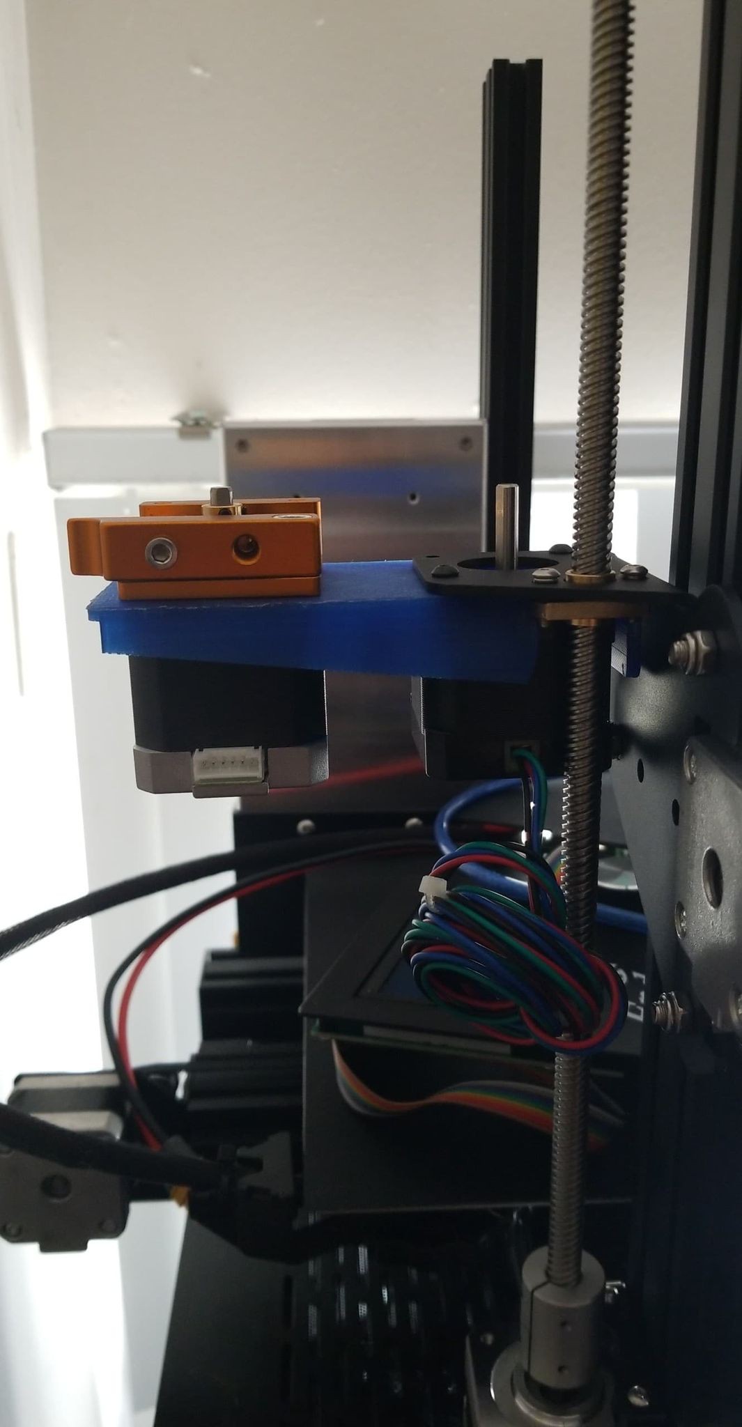
After that though it fits pretty nicely on the z-carriage:
only other thing to note with that mounting scheme is that the screw holding the inner z-axis bearing protrudes out just enough to conflict with the first stepper after it's lowered an 1/8" relative to the rest of the carriage because of the thickness of the new mounting bracket. There was a washer on that side of the carriage though, which when moved to the other side reduced the amount that screw protrudes just enough for the stepper to fit.
I'm still waiting for some longer socket head screws to be able to mount the extruder frame block to the stepper through both the z-carriage and the second stepper mount.
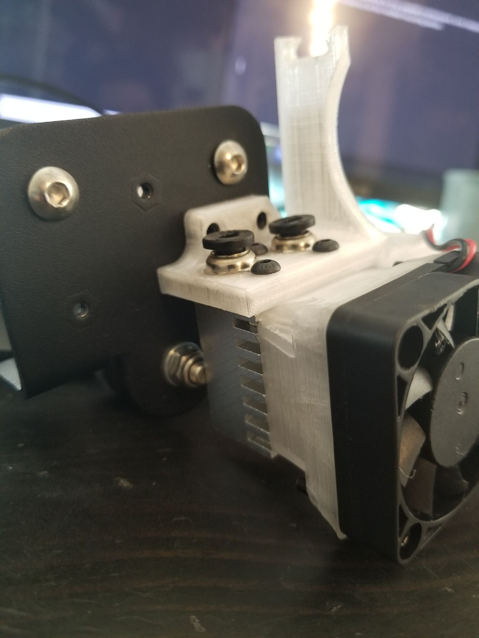
The hotend mount from krestoverson (https://www.thingiverse.com/thing:2854282) fit very snugly around the mounting holes on the x-carriage, so I don't think screws are needed for that:
The original heatsink cooling fan needed the printed adapter (https://www.thingiverse.com/thing:1049548) to fit, but as krestoverson noted you can't use the 12V fan that comes with the hotend since the ender 3 supplies 24V power. The mounting slot for the part cooling fan didn't print properly, but I should be able to still hold the fan with a washer for extra support area.
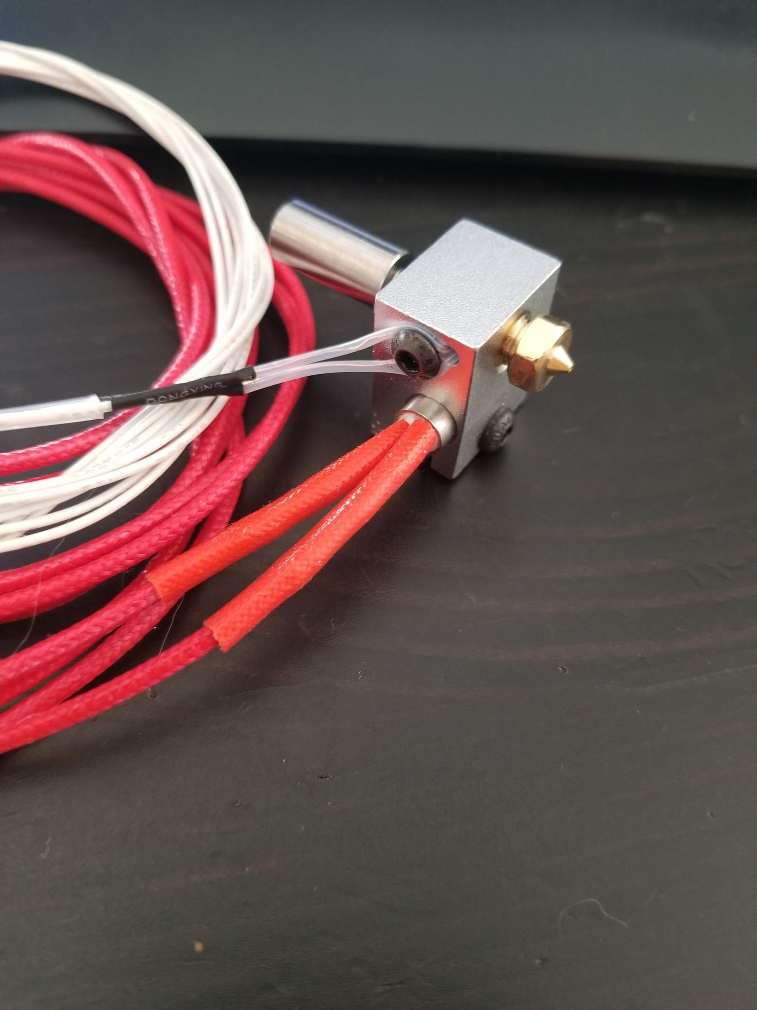
Assembling the heater blocks was kind of tough to figure out since I haven't done anything like it before but I think I'm on the right track. I'll definitely add washers to the screws that are holding in the thermistors (didn't come with the hot end kit). I also had to separately purchase the 24V heater cartridges, as the kit comes with 12V cartridges. The thermistors come already sealed in tubing and with heatshrink at the joint between them and the wires going to the control board, but the wires are bare ended so I'm waiting on the proper crimp connectors to interface the thermocouple with the control board. There were various online resources I followed to figure out how to put this part together, the most helpful was from the E3D wiki (https://wiki.e3d-online.com/Cyclops_%26_Chimera_Assembly), but I haven't heated it up yet because I'm waiting for the thermistor connectors so I'll wait to call that a success until I've actually heated/tightened the nozzles and get them level. Also waiting on the thermal grease which is recommended for getting good heat conduction from the throat to the heatsink.
Finally the motherboard enclosure from TeachingTech for the MKS Gen L was simple enough to modify for the Base board.
It has the same Rs values for the stepper drivers and the same family of drivers (A498...) as the Creality3D V1.1.4 board that came with the printer, so I read off the stepper Vref voltages on the stock board and adjusted the ones on the MKS Base to match as close a possible. Knoopx had measured Vref values on his stock V1.1.2 board (https://gist.github.com/knoopx/e6c40a009e796203b93a75a3ed6a5ab8) and the values I measured were more-or-less the same:
Driver:
Vref:
Extruder
.728
X
.557
Y
.569
Z
.557
For the stepper I ordered for the second extruder, which has a 2A current rating, setting the driver to 90% meant trimming the Vref to 1.44V.
I've attached the current marlin firmware configuration I'm using (rev1 9/25/20).
I had to compile it with platformIO, there was a weird bug with using the arduino IDE because of how long command line instructions can be.
Also of note, the EXP1 and EXP2 connectors on the MKS Base are upside down, so I had to chop off the orienting nub on the ribbon wire connector and plug it to the board upside down to get the display to work.
Will update once I have the additional screws and crimp connectors and hopefully will have the new hotend up and running and ready for tuning.
 P
P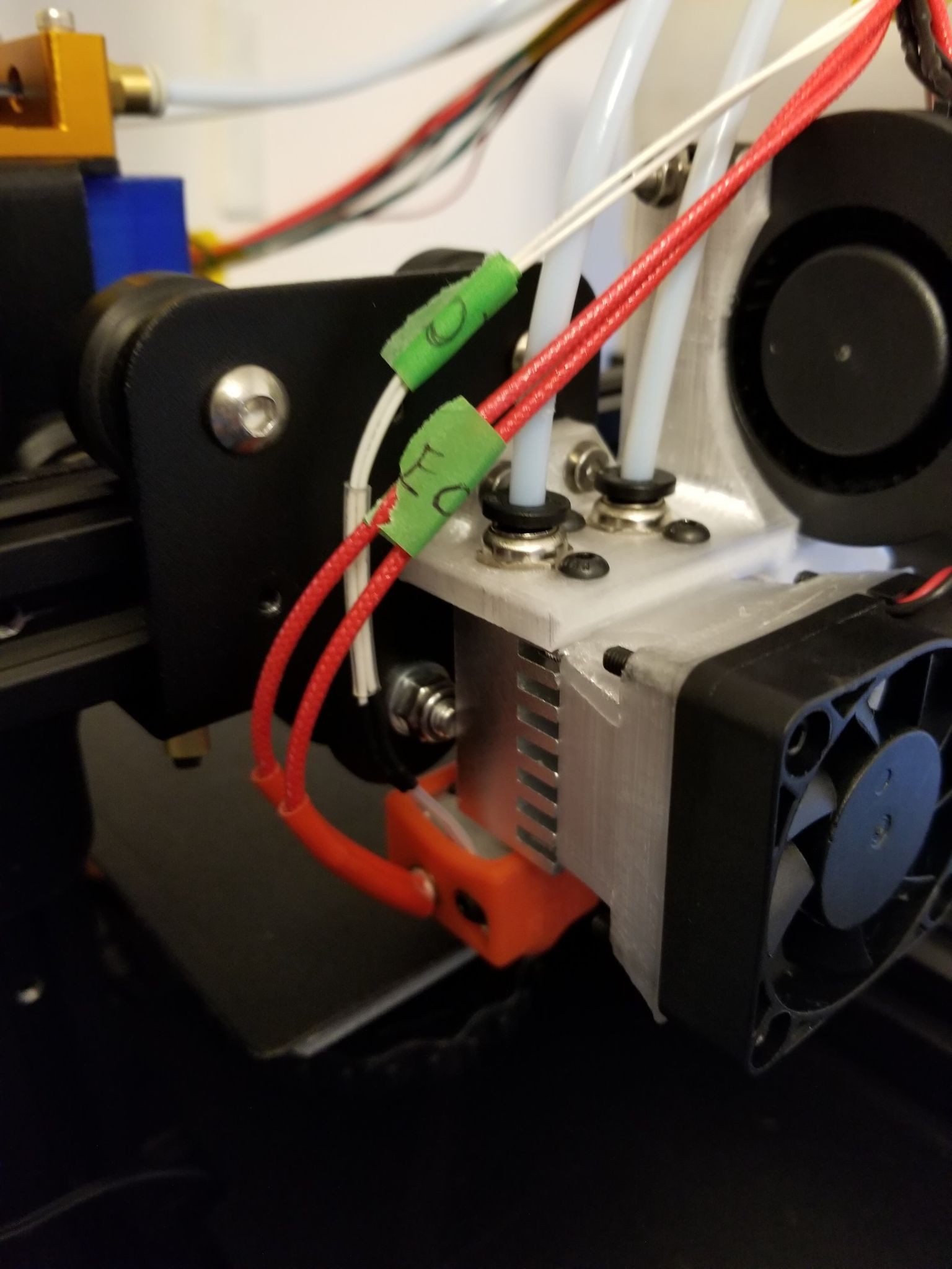
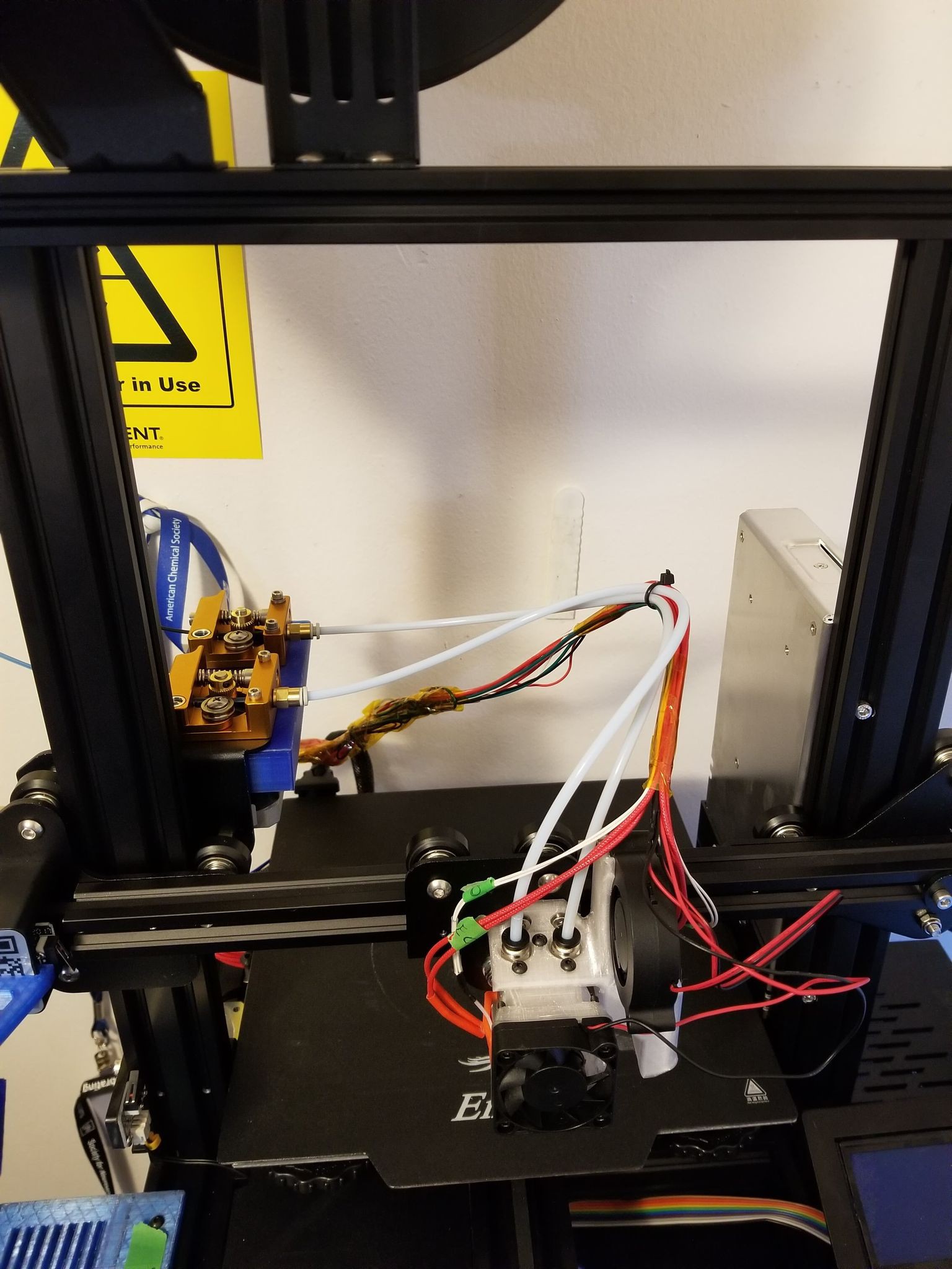 You'll need a custom printer profile in cura, I just copied the X/Y min/max settings from the Ender 3 Pro profile. There are nozzle offsets you can play with in the extruder tabs, but I haven't messed with those values yet.