-
Convection Fan
08/31/2021 at 23:41 • 0 commentsIntroduction
One of the biggest issues people report with these ovens is that some parts of their PCBs don't get hot enough to reflow the solder while other parts get so hot they components start to get burnt. In Jerry Walker's video series he adds and small convection fan and concludes this is one of the most beneficial modifications to prevent this issue.
This was, by far, the most difficult modification. It requires adding a motor, a switch, and the fan blade. However, the ideal position for the fan blade is in the center of the heating chamber and there is a thermocouple located there. I chose to relocate both thermocouples to the side of the chamber. This also freed up room above the heating elements to allow the fan blade to be installed between the heating elements and the top of the chamber.
Relocating the Thermocouples
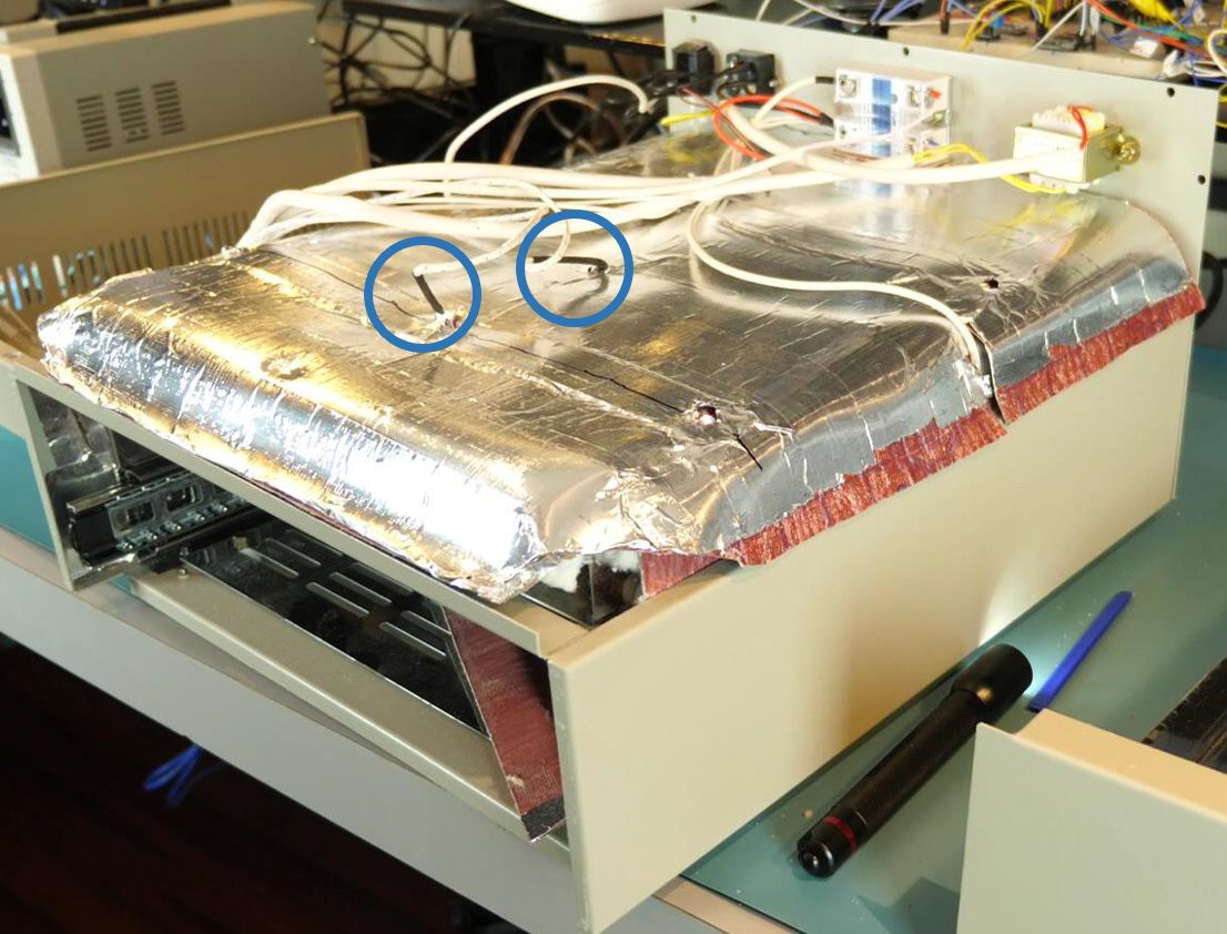
The thermocouples were originally located at the top of the chamber.
![Original Location of the Thermocouples Original Location of the Thermocouples]()
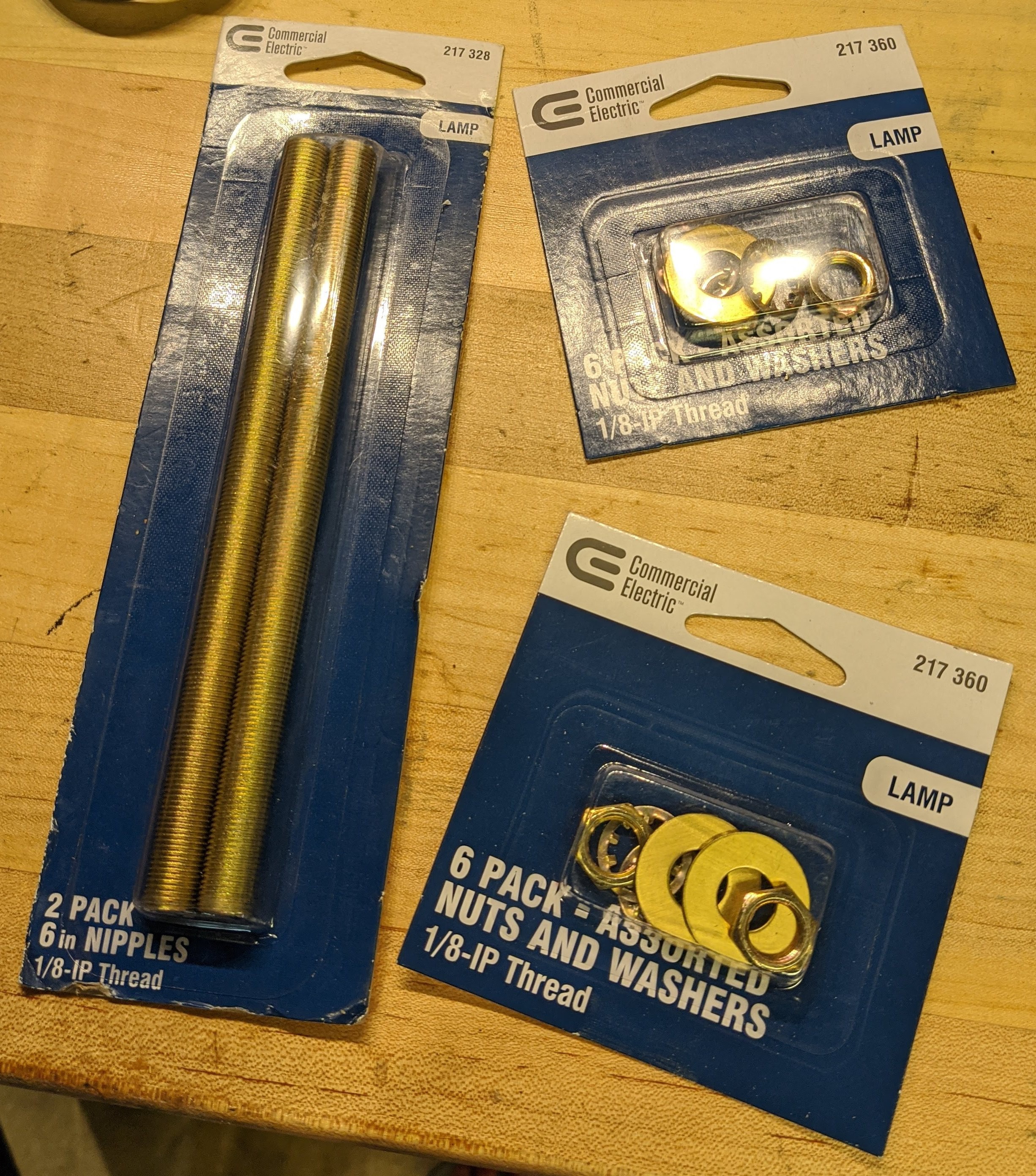
The original location of the thermocouples (blue circles). To mount the thermocouples to the side of the chamber, I used some lamp hardware. It is cheap and available at most home centers. The hardware is metal so it will stand up to the heat, the nipples are hollow which allows running the thermocouples through them, and there is nuts and washers for mounting everything.
![Lamp Hardware Lamp Hardware]()
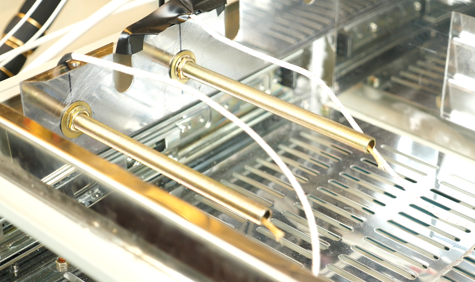
The lamp hardware used to remount the thermocouples. This hardware is cheap and readily available at home centers. I drilled some holes big enough for the nipples through the side of the chamber. A washer and nut on each side of the chamber wall held them in place. Then it was just a matter of running the thermocouples through and applying some heat-resistant silicone to seal them.
![Relocated Thermocouples Relocated Thermocouples]()
The thermocouples related to the side of the heating chamber and mounted with lamp hardware. Motor
I chose an N20 hobby motor. It works, but the thing is very noisy. If I was to do this again, I'd definitely look for a quieter motor. A 12v motor was selected so it could run directly off the power available on the control board.
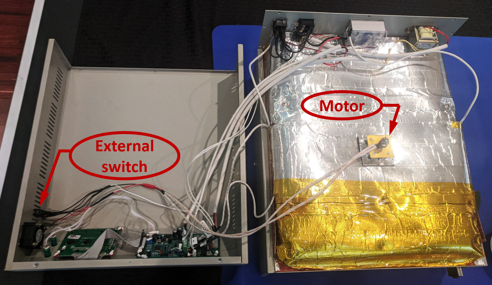
Some standoffs were used to attach a small plate to the top of the heating chamber. A square was cut out of the insulation to allow it to be positioned around the stand. The insulation square that was cut out was then modified to fit between the standoffs and allow the fan driveshaft to pass through. The motor was mounted above the insulation to prevent it from overheating.
![Motor and Switch Motor and Switch]()
The motor for the convection fan is mounted to the top center of the heating chamber. It is mounted above the insulation so it does not get too hot. A separate, external switch was added to allow it to be controlled independently. An external switch was added to allow independent control of the convection fan. Heat shielding was used on the wires from the motor. Disconnects were added between the motor and switch to allow service of the oven or motor replacement.
Fan Blades
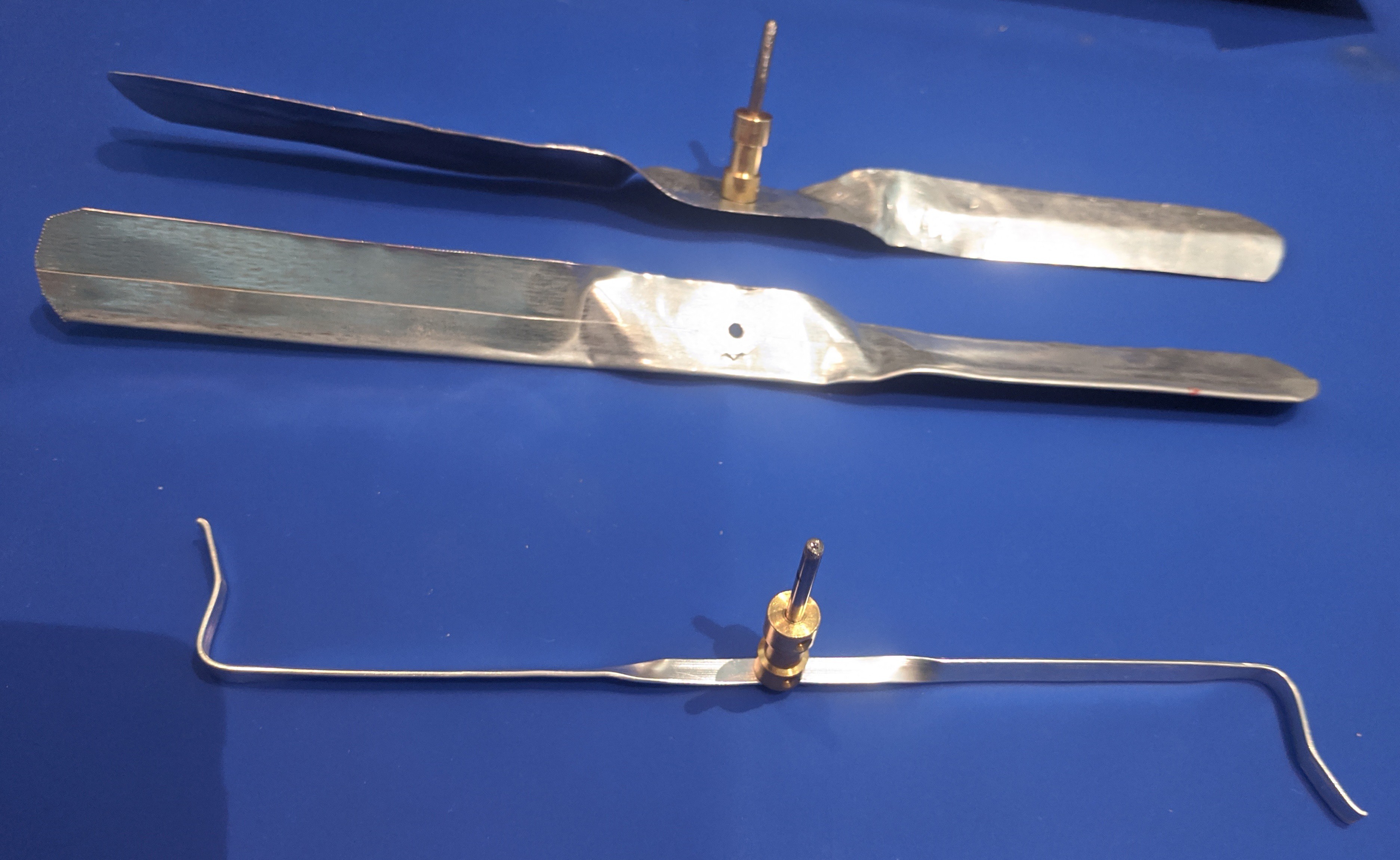
I made two different sizes of fan blades. The first was as close as I could match to the one Jerry Walker created. The second size was much larger. After testing, the larger fan blade led to a large discrepancy between the readings of the thermocouples and what I was reading on a PCB placed in the oven. In the end, I went with the version Jerry Walker used.
![Fan Blades Fan Blades]()
Two different sizes of fan blades were tested. The bottom one was determined to give the best results. -
Temperature Profile Testing
04/25/2021 at 17:20 • 0 commentsIntroduction
Before I started to run PCBs through the oven, I wanted to characterize the behavior. I ran a series of trials where I measure the temperature at a PCB with a multimeter. That way I could compare the temperature at the PCB with the oven's programmed temperature profile.
Initial Observations
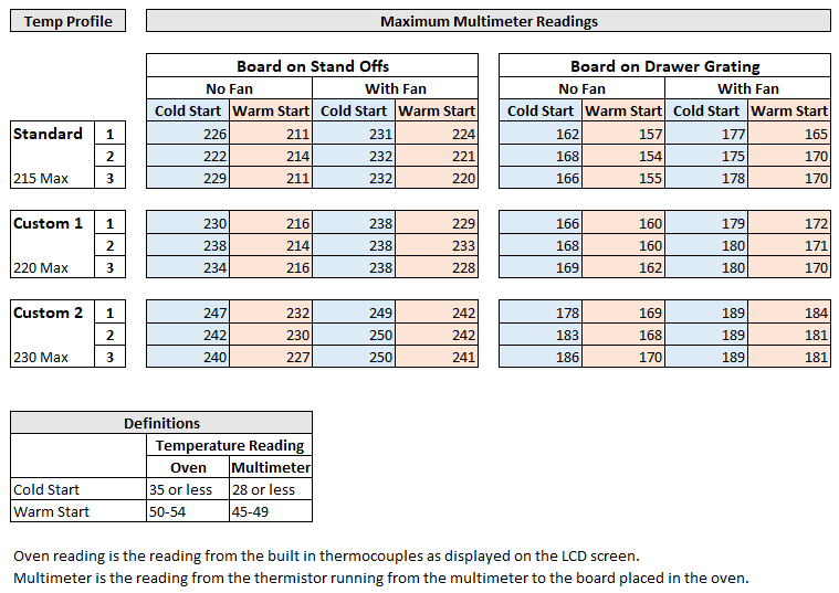
I quickly noticed a few things. Most of these items were not surprising, but they are important to be aware of. Notably:
- The maximum temperature reached at the PCB was different than the profile's maximum temperature.
- The temperature at PCB was slightly lower than the manufacturer's recommendation for the solder paste I had (using the standard leaded profile).
- When the board rested directly on the drawer bottom, the temperature was lower than when using standoffs to place the board on.
- Running the oven consecutively resulted in a different temperature for the second trial than the first.
- The temperature reached varied depending on if the convection fan was used or not.
- The PCB did not reach maximum temperature until after the oven. The oven is in the cool-down section by the time the board maxes out.
Temperature Profiles
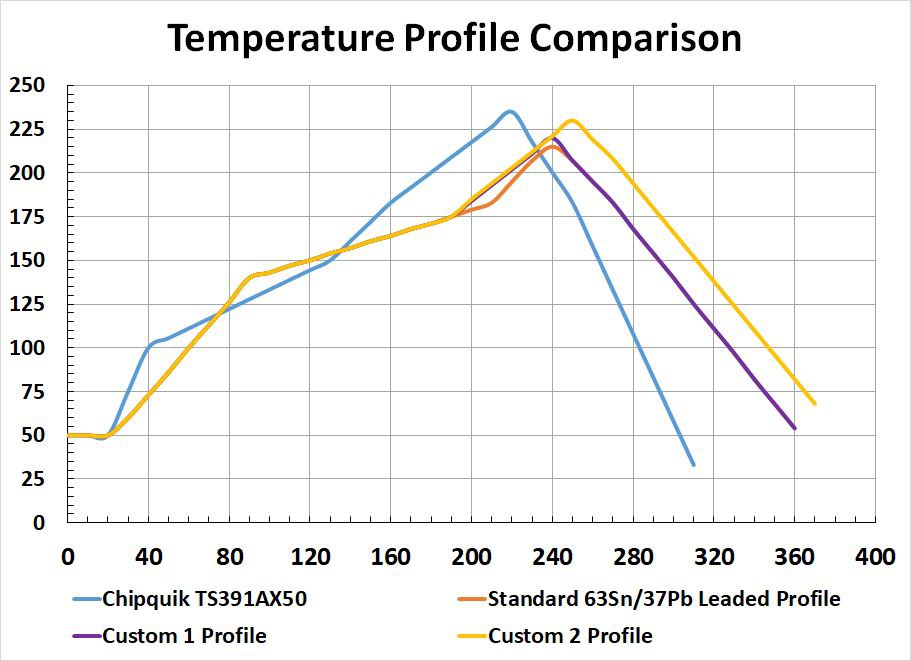
The standard temperature profile for leaded solder that comes with the Unified Engineering firmware. It was consistently slightly low for the solder paste I was using. Therefore, I created two new profiles for testing which reached a slightly higher temperature.
After some initial testing, it seemed that the oven could not keep up with the temperature profile (temperature climb rate). In addition, some testing showed that the standard profile that came with the oven could reflow the solder when testing without part. Therefore, I decided to slightly modify the standard profile rather than trying to use the profile provided on the solder paste data sheet. The profiles are compared in the graph below.
![Temperature Profile Comparison Temperature Profile Comparison]()
Temperature profile comparisons for a solder paste, the built-in profile from the Unified Engineering firmware, and two custom profiles. Methodology
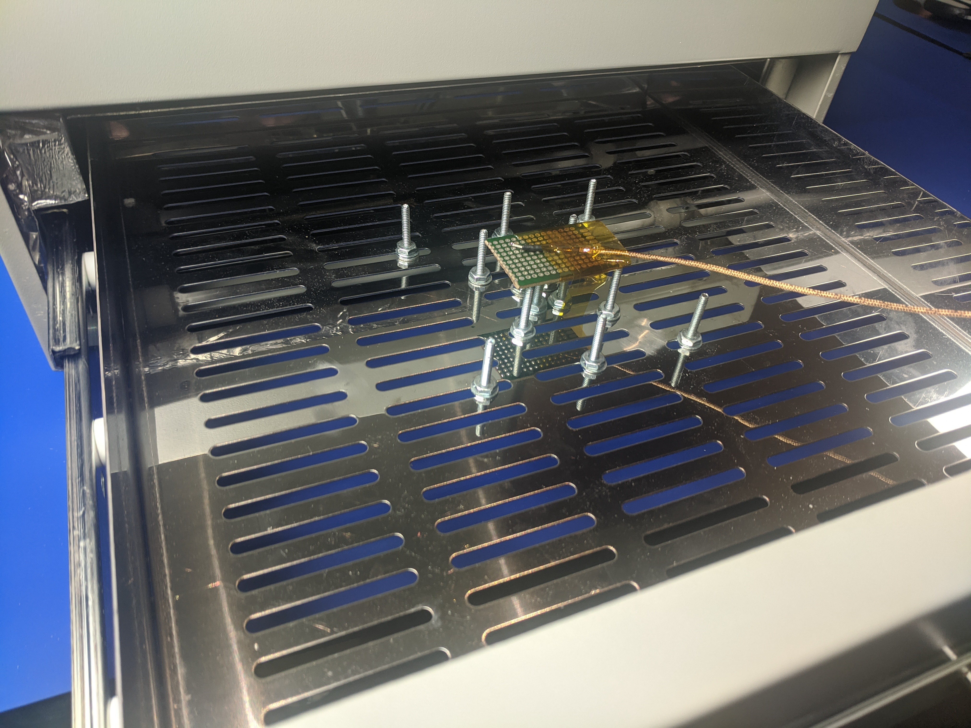
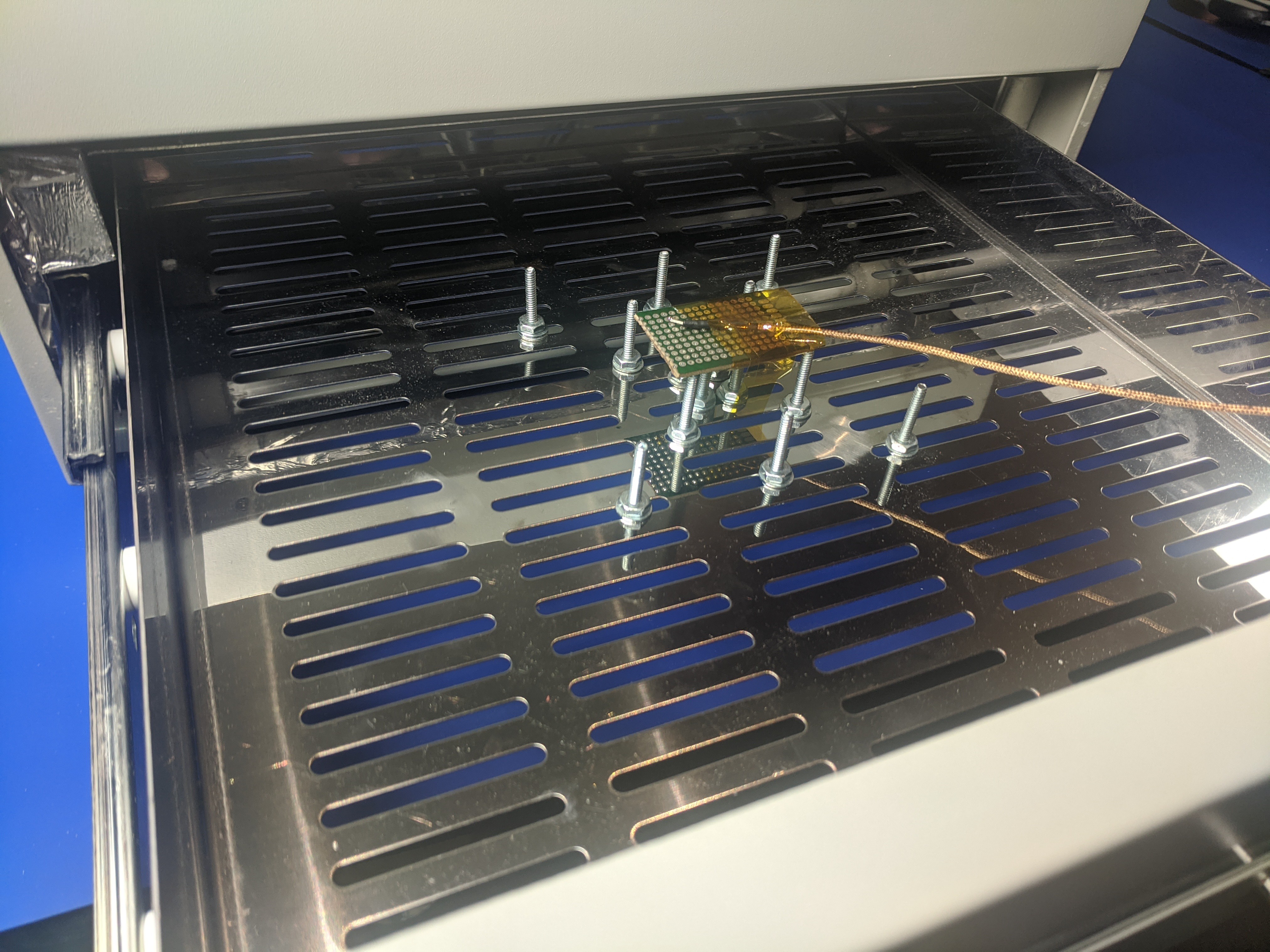
The temperature probe of a multimeter was hooked to a multimeter, ran through a slot at the bottom of the oven drawer, and attached to a PCB (a piece of protoboard) in the center of the oven. See the picture below. Readings were taken for:
- 3 temperature profiles
- With and without the convection fan running
- With the board on stand offs and direction on the drawer bottom
- Cold start (oven completely at room temperature) and warm starts (oven above room temperature as a result of a previous run)
Each combination of variables was run 3 times.
![Temperature Probe Placement Temperature Probe Placement]()
The placement of the temperature probe in the oven. This is for runs with the stand-offs. For board was directly on the drawer for some runs. Results
The results are shown below. You can download the excel file with all the data and each of the temperature profiles used from the main page.
![]()
-
Replace Masking Tape with Kapton Tape
10/16/2020 at 21:47 • 0 commentsIntroduction
There are reports that the masking tape used on the inside gets too hot and starts to smell. I ran the oven through one heat cycle with the masking tape and didn't notice the powerful odor reported. The masking tape seems to on the outside of the insulation where it shouldn't get that hot. While this is one of the most common modifications, it seems many people do it off of reports of an issue rather than having the experience themselves. I tore my machine down more than most and found a couple of pieces of masking tape I had not seen reported before. Most probably miss these pieces and yet experience no issues. However, it is one of the easiest modifications and the effort could prevent a potential issue.
Masking Tape Locations
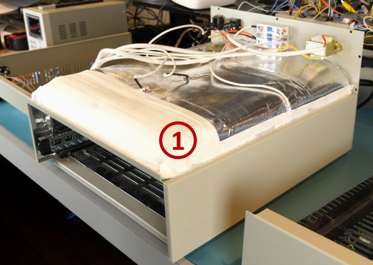
The main group of masking tape is apparent as soon as you take off the lid. It covers the top of the insulation cover.
![]()
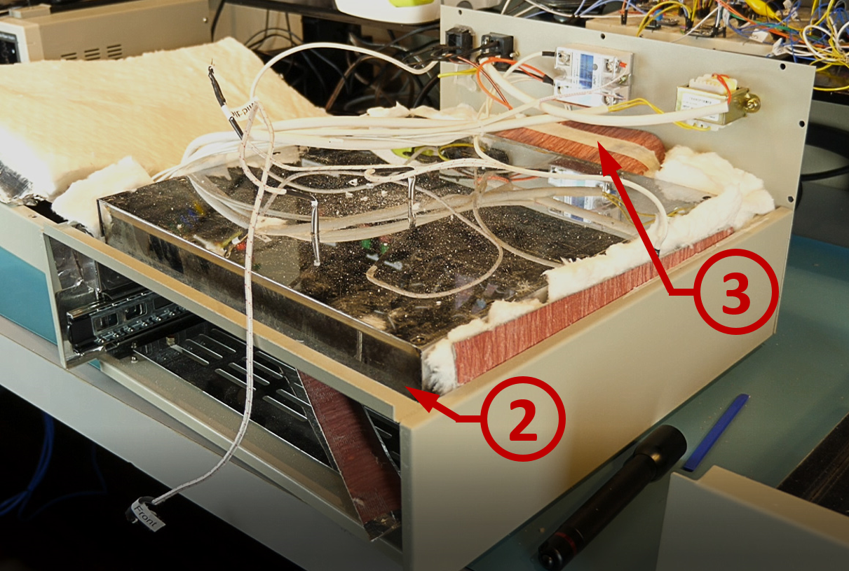
The other two locations are ones I suspect most people miss. To get to them you have to remove the insulation cover and the insulation.
The second location for masking tape is on a strip that closes a gap just behind the top front lip.
The third location is a strip of masking tape holding down a cover to the back fan.
![]()
-
Drawer Stand Offs
10/07/2020 at 21:52 • 0 commentsIntroduction
Standoffs are used to keep the PCB off of the large metal drawer bottom. This has two effects. It results in a smaller contact area that prevents the drawer from acting like a heat sink. It also raises the PCB up so that it is closer to the thermocouples and should make the temperature more accurate.
Installation
This is one of the simplest, and arguably most beneficial, modifications. The screws are placed through the existing slots in the drawer bottom and tightened up. You don't want to over tighten and damage the drawer, but I do recommend using tools and not just hand tightening. Lock washers would be beneficial. The repeated heat cycles have a tendency to loosen the screws.
I used some #6 by 1 inch for the sole reason that I had some left over from another project.
![]()
-
Replace Side Fan
10/07/2020 at 21:16 • 0 commentsIntroduction
The side fan is very noisy and runs whenever the unit is on. An equivalent fan can be substituted that is virtually silent.
Original Fan
I tracked down the specifications of the original fan. The details, for reference, are below. It's possible your fan is a different model, but the specs should be pretty much the same.
- Sanyo SanAce40
- Model number 9A0412J7D07
- 40mm x 40mm axial fan
- 15mm deep
- 12v
- 0.11A
- 6.2 CFM
- 28 dB
- 7500 RPM
- 2 wire
New Fan
The fan I selected is a Sunon Fans model 4129/HA40201V4-1000U-A99. It is similar to the original with a few important differences.
- 20mm deep
- 5.5 CFM
- 12.3dB
In selecting this fan, I sacrificed a little CFM to get the quietest fan I could. This fan is nearly perfectly quiet. If I had to do it over again, I would try to get a little more airflow even at the expense of a little more noise.
Installation
The installation is easy enough, but there are two things you should be aware of.
Bolts
If you select a 20mm deep fan instead of a 15mm (like the original) it will fit, but you do need to replace the original screws with longer ones. You will need 4 M4x30mm (0.7mm pitch) screws.
Fan Connector
Likely your new fan will come with a connector different than the one on the existing fan (or it won't be long enough). I chose to cut the old connector off and use it for the new fan.
-
Add External Access to ISP Header
10/07/2020 at 18:24 • 0 commentsIntroduction
In order to update the firmware, you have to access the ISP header on control board. This means removing the top of the oven which is rather inconvenient if you need to do it with any sort of frequency. After running the oven a few times, I realized that I would probably have to update the firmware to add or modify heating profiles so I added an external connection to the ISP header to make this a simple process.
There are some individuals that have chosen to install a USB to UART board in the oven and then have an external USB connection. I didn't feel the need to sacrifice a board just for this purpose so I installed a wire pass through to connect to the pins I needed.
Installation
Design Requirements
I decided on a few design requirements.
- I didn't want loose wires hanging outside the oven so simply running a set of wires through the side wasn't an option.
- I wanted to be able to plug my USB to UART board in directly without additional cables. This meant I needed external make pins as my board has a female header installed.
- The external pins should be protected from damage.
- When plugged in, the external board shouldn't bend the pins and should be supported by the connection.
- The installation should have a clean look.
Design
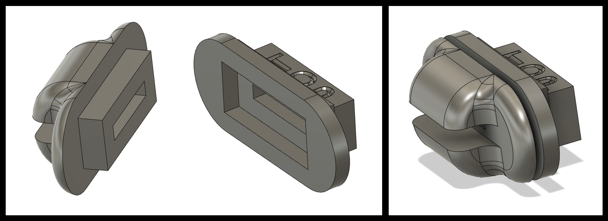
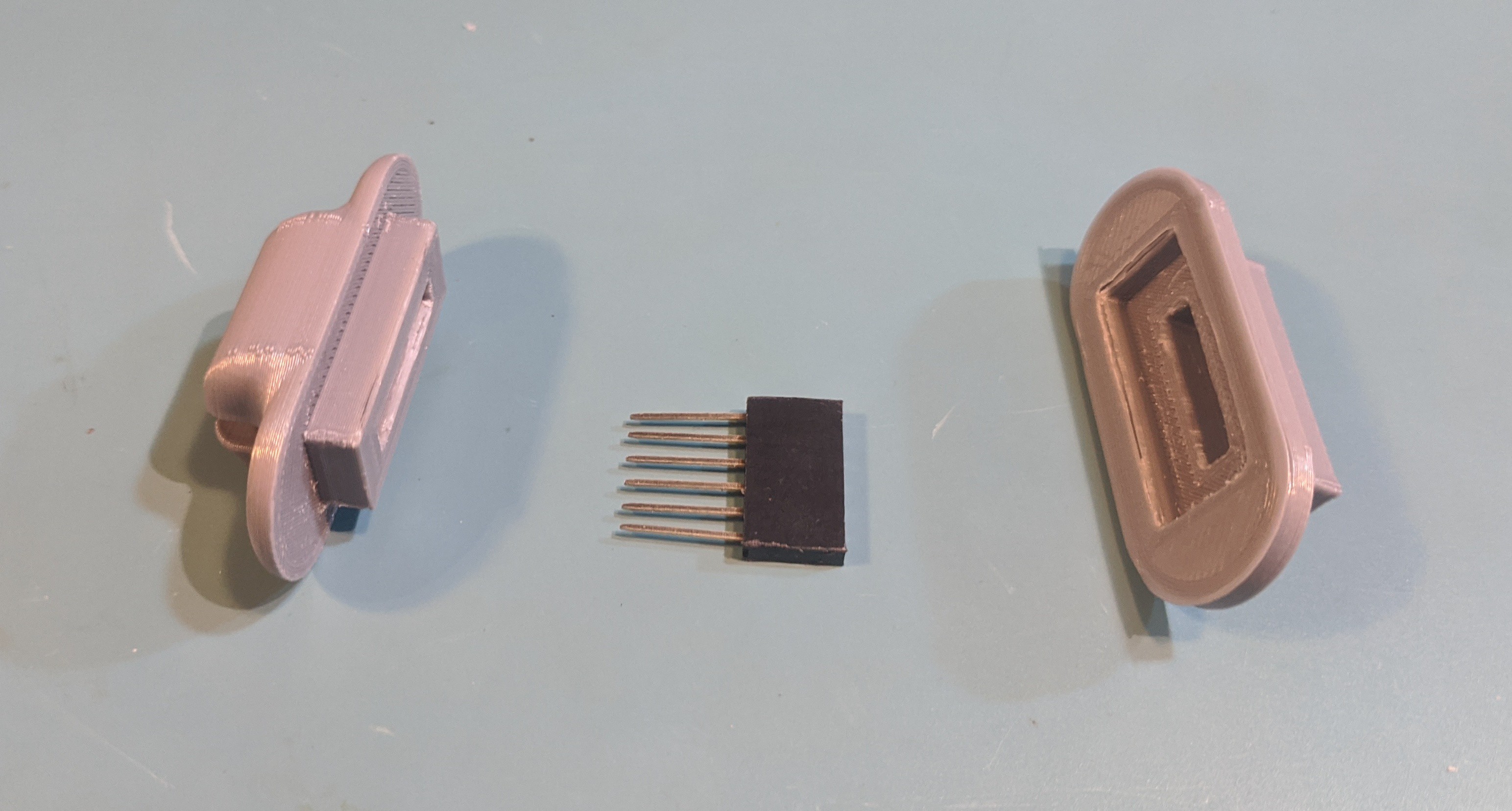
After scrounging around my parts bins to see what I had that could work, I came up with the following solution. A stacking header would be used as the pass through connector. The long pins of the stacking header give it the reach needed to pass through an enclosure and have plenty left over for connected to the USB to UART board. On the inside, a custom jumper cable would be made to go from the stacking header to the ISP header on the oven controller.
The stacking header would be housed inside a custom designed and 3D printed enclosure that could hold the header in place, provide a clean look, and have ledges to protect the pins and provide support for the USB to UART board.
![]()
![]()
Installation
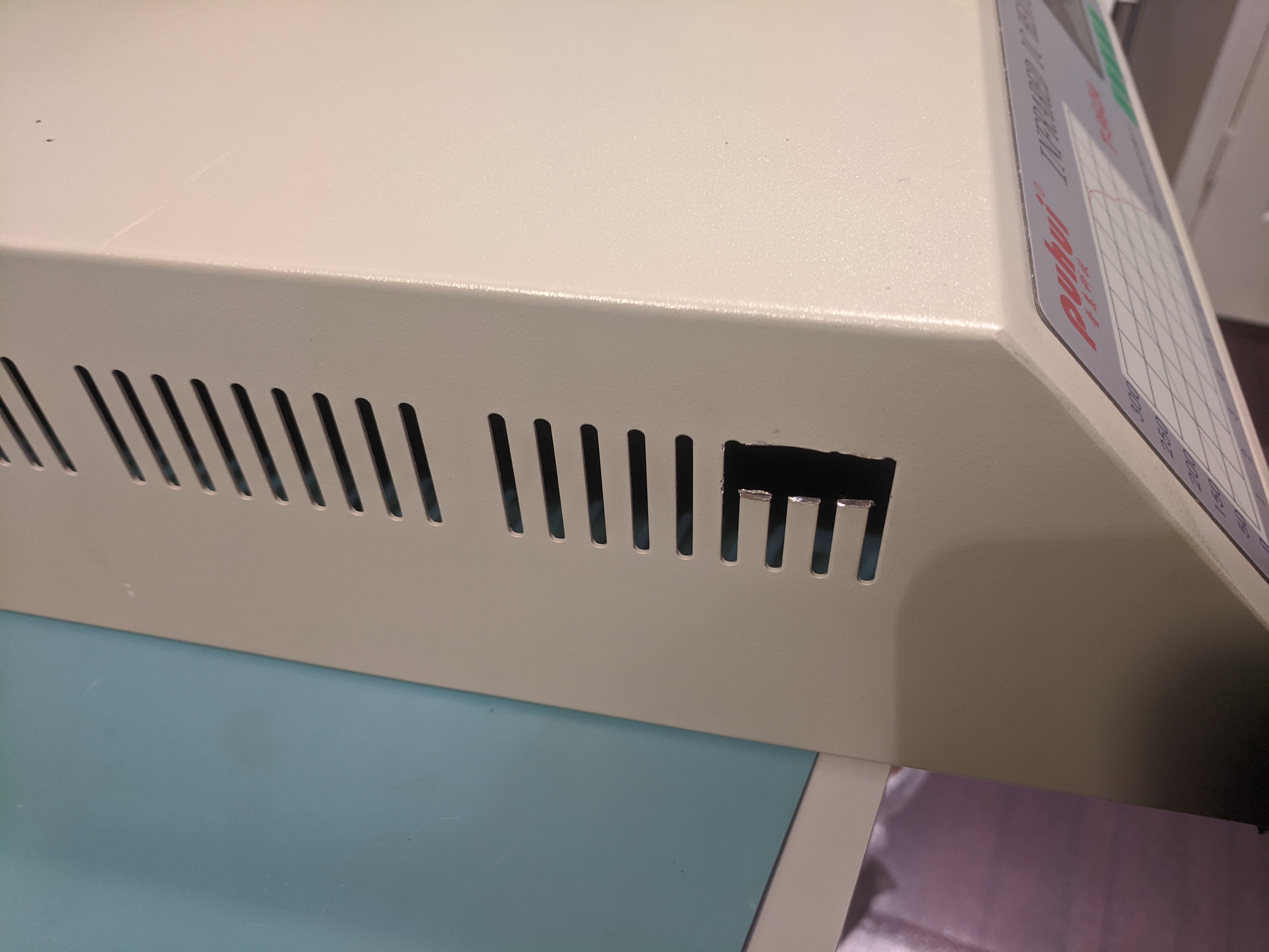
I used a Dremel with a metal cutting wheel to cut through the tops of 4 vent slats in the side of the oven. The opening was large enough for the center of the outside connector to pass but small enough that it was covered by the connector flanges.
![]()
The stacking header was put inside the connector. The two connector halves where sandwiched around the side of the oven and some cyanoacrylate glue used to stick everything together.
![]()
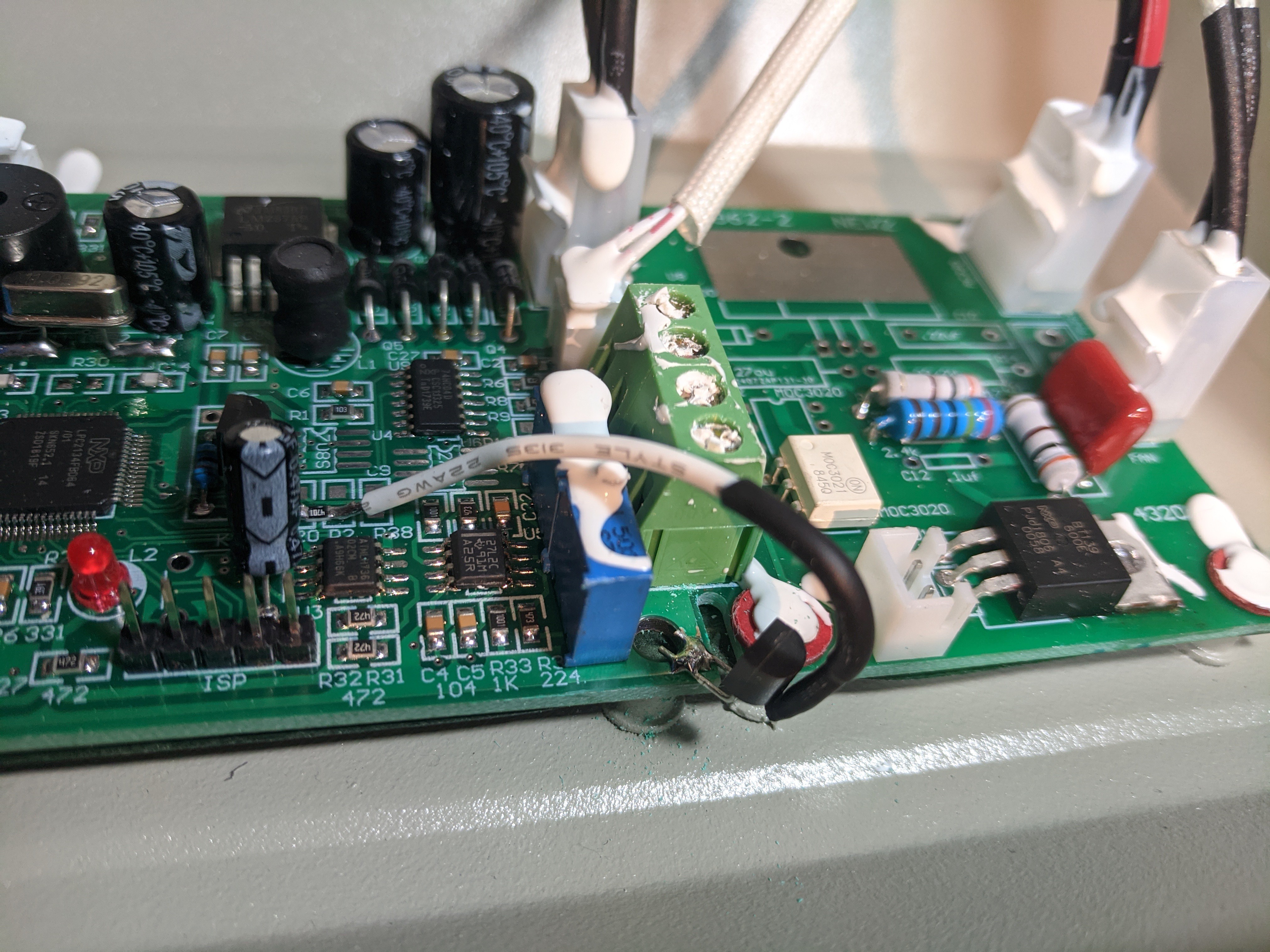
With the connector installed, I made a custom cable to connect from the stacking header to the control board. It uses some crimp style JST connectors: male for the stacking header side and female for the control board side.
![]()
Resources
If you want to use my connector, you can download it at the link below. You can also access the Fusion 360 file and modify it as you see fit.
There are two "Inside" pieces of the connector and you only use one. One inside piece is general and allows you to access all the pins on the stacking header.
The only inside piece is specifically for use with the Sparkfun board and blocks the unused pins. If you use this piece, it has an orientation and you have to install the side with the "top" text towards the top of the oven. You might be working on the oven lid upside down so don't confuse the orientation.
Connector STLs:
https://www.thingiverse.com/thing:4616526
Fusion 360 Design Files:
-
Back Fan Opening
10/06/2020 at 19:53 • 0 commentsIntroduction
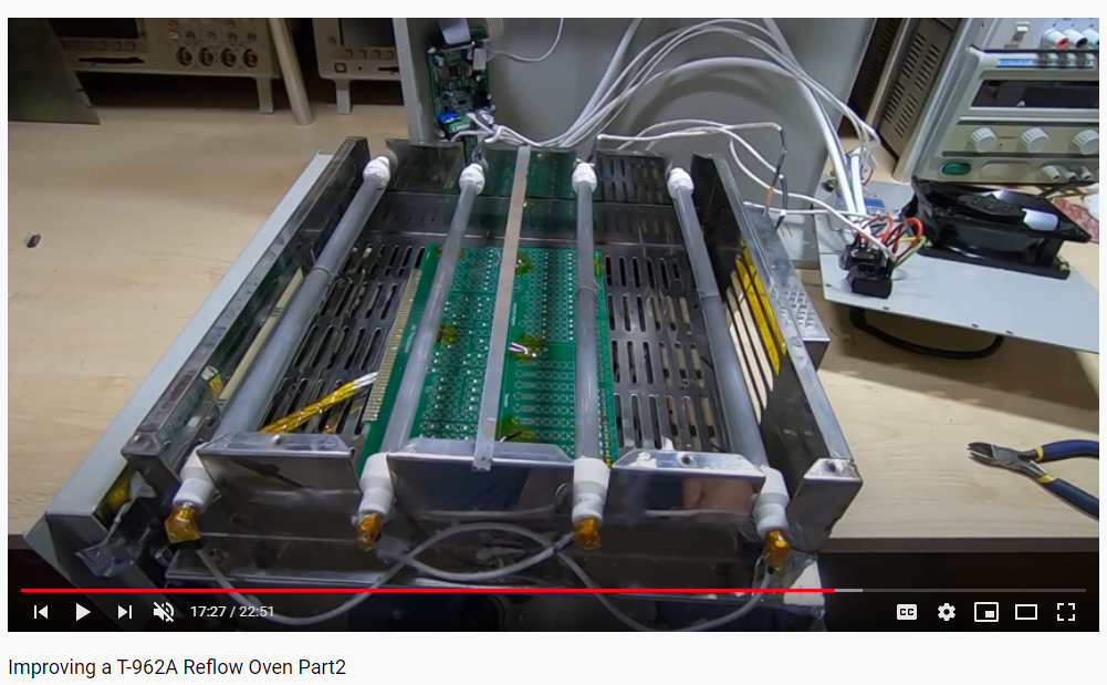
In Jerry Walker's videos, he concluded one of the most significant issue was that the back fan opening allowed cold air in during heating and sucked too much heat out during cooling. He suggested partially closing the back fan entrance. In the image below, you can see he has partially closed his off with Kapton tape.
![]()
2020 New version
In the updated version, they have added louvers to the back fan opening. This provides and even better solution by nearly completely closing off the opening during heating and partially restricting the air flow during cooling. The louvers are one big reason to make sure you look for the new version when you go to purchase your oven.
-
Cold Junction Compensation
09/29/2020 at 03:19 • 0 commentsIntroduction
The cold junction modification adds a temperature sensor to measure the temperature at the board. The new firmware uses this to correct the temperature readings from the thermocouples and make the heating process more accurate.
Sources
Cold junction compensation page:
https://github.com/UnifiedEngineering/T-962-improvements/wiki
Unexpected Maker video:
https://youtu.be/HjYqSfLzBKk?t=119
Note that Seon has his oven on the side so he doesn’t have to detach the cables. However, if you put the top to the left side of oven (as opposed to the right as he has it) the cables reach (at least they did for my oven) and you can leave the oven flat.
Hardware
The temperature sensor I used can be found here:
https://www.digikey.com/product-detail/en/maxim-integrated/DS18B20-/DS18B20--ND/956983
When you read the datasheet it tells you that you need a 4.7kOhm resistor as well. I used these:
https://www.digikey.com/product-detail/en/yageo/RC0805FR-074K7L/311-4.70KCRCT-ND/730876
If you use a different temperature sensor, make sure it meets the requirements of the new firmware and be sure to check the data sheet for wiring.
![]()
-
New Firmware
09/28/2020 at 20:34 • 0 commentsIntroduction
If you have never upgraded firmware for a board before, this could be somewhat intimidating to some. Largely because if you do it wrong, you risk bricking the hardware. The manufacturer never intended the user to upgrade the firmware, so it isn't the simplest process. However, the process is very well documented so with a little preparation, anyone should be able to handle it.
There are various methods and tools to flash the firmware. I will list the ones I used and verified that work.
To start, be sure to read through the entire page for the firmware upgrade on the Unified Engineering page. Also watch Seon's video on the upgrade.
Firmware Github page:
https://github.com/UnifiedEngineering/T-962-improvements/wiki/Flashing-the-LPC21xx-controller
Seon's video:
https://youtu.be/pIGK9VNppWw?t=40
Notes on Required Resources
To do the upgrade you will need the binary firmware file (hex file), software to transfer the binary file from your computer (Flashmagic), and a USB to serial converter. Links to the hex file and Flashmagic software can be found on the firmware upgrade Github page.
Getting the Hex File
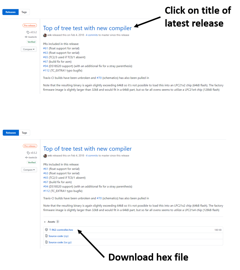
To find the hex file, go to the firmware Github page. At the top of the page is a link for the latest releases. Once you click the link, it may not be obvious where to get the hex file. You need to click on the title for the latest release and that will take you to a page to download the file.
![]()
Hardware
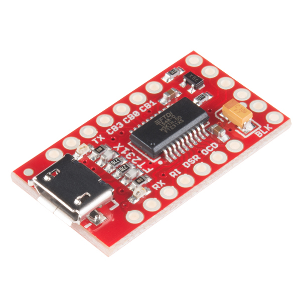
You will need an USB to URT board. There are many options available. The one I used is linked below. Please note that this board ships as 5 volt and you need to change it to 3.3 volt to use it with the T-962(A) control board. Instructions for doing this are on the Sparkfun website.
https://www.sparkfun.com/products/13263
![SparkFun FT231X Breakout]()
Notes on Upgrade
I won't go through the process step by step as the firmware page and Seon's video do a good job of that. I will note some differences in the way I did things as it may be useful.
Top Removal
When Seon worked on his oven he had to tip the oven on its side to allow the top to sit flat on the table. He had his top to the right of the oven. I put the top on the left side and it would reach without tipping the oven. I'm not sure if the side makes a difference or if the wires in my oven were longer.
Breakout Board to ISP Header Hook Up
I put my breakout board on a break board to prevent it from touching bare. I taped the breakout board down so it wouldn't slide off the bread board. The bread board was also used to ease the process of entering the firmware upgrade mode. I could use a row on the break board to temporarily ground the n_ISP and n_RESET pins. I have soldered a row of header pins on my USB to UART breakout board to make using it easier to use. That isn't required, you could use the header at the end of the board normally used to connect to your device.
![]()
-
Grounding Check
09/28/2020 at 17:03 • 0 commentsSeveral owners reported that these machines are not grounded well and this is a potential safety hazard.
This seems to be one of the issues addressed, or at least partially address, in the “2020 New version.” I tested the grounding and it seems to be grounded. Inspecting the screw holes, there is still some residue that may prevent the best possible grounding, but there seems to be enough raw metal exposed to make an electrical connection between the different chassis parts.
Use your multimeter or a continuity tester to check your machine. You can watch Seon's video on checking and correcting this issue:
T-962A Reflow Oven Modifications
Modifications to a T-962A reflow oven which turn this cheap oven to a surprisingly effective piece of hardware.
 Lance
Lance