-
1Building your H-Field Probes
For this project, we're going to focus on H-field probing, since it tends to offer excellent sensitivity and resolution, and building acceptable and useful H probes I think is easier than building acceptable E field probes.
But wait, H field vs E field? Magnetic field vs Electric field. Where the electric field radiates out from relevant conductors and stubs, the H field radiates around them, just like a non-contact voltage tester senses the electric field near a live mains wire, while a current clamp senses the magnetic field around it due to current flow.
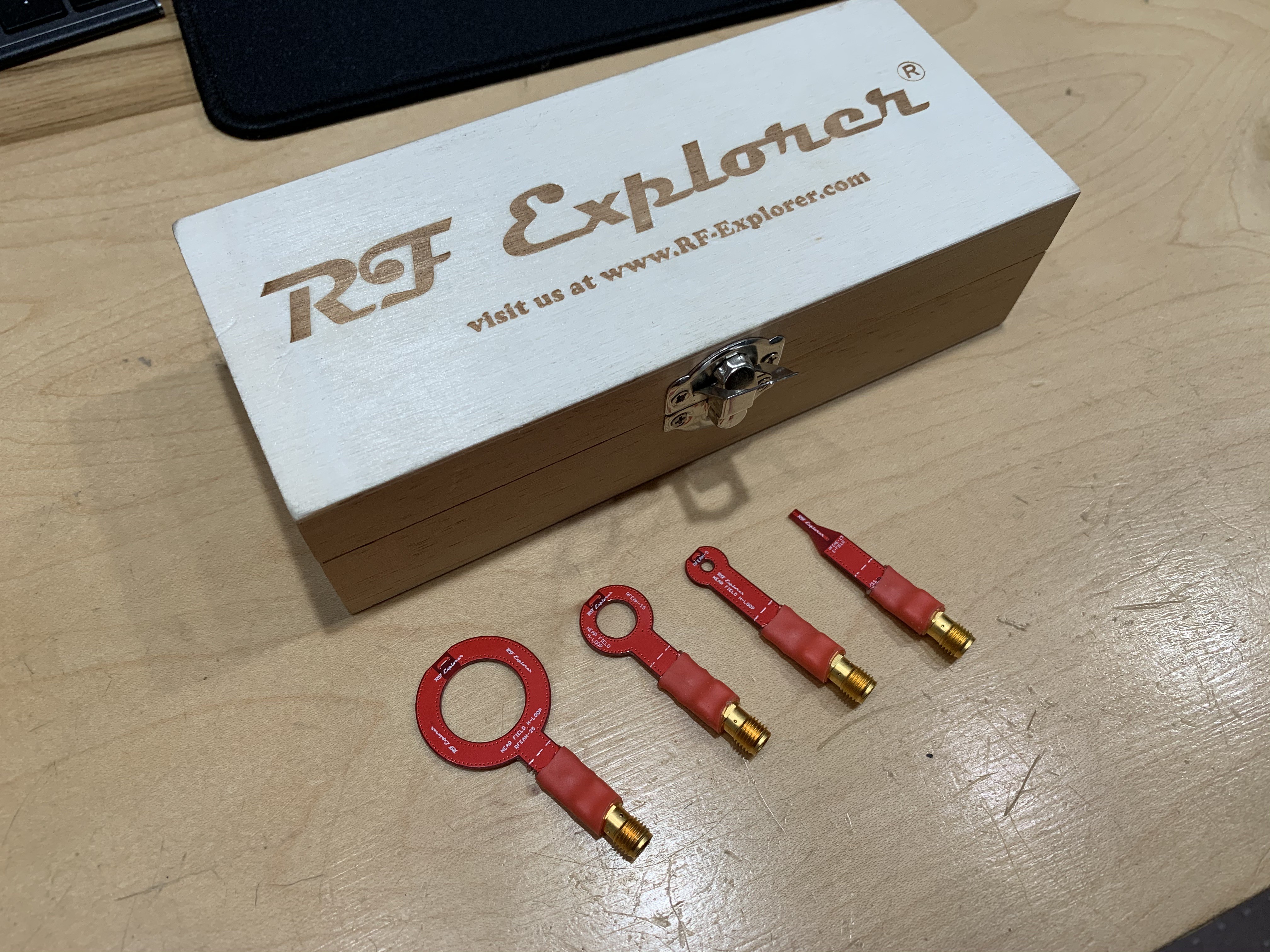
In fact, that's an important distinction: E field probes sense AC voltage changes on a wire, where H field probes sense AC current flowing around a circuit. As it turns out, in very close to the circuit board, sensing AC currents gives you a much better sense of which devices and wires are responsible for which noise frequencies compared to sensing voltages. Case in point, have a look at this commercial set of near-field probes:
![]()
You might notice that three of them are loops and only one is a straight stick: three are indeed H-probes, while only one is an E-field probe. In part, that's because different size H probes give different trades between spatial resolution and sensitivity: bigger is more sensitive, but smaller tells you more precisely where the signal is coming from in space. E-probes don't have quite the same trade. But it's also a reflection of how much you'll be using one vs the other in practice. In my experience, you'll spend more time swapping between the H probes to zero in on a particular area of the board, where you might use the E probe to find one trace vs another. And with the ultra-fine H probe we'll be making, you might not even need that.
I'll skip for now the theory of how to make the perfect probes, because the probes below are MUCH simpler and still totally adequate for our purposes. I'll get into shielding a bit in the actual workshop, and you can experiment with it after the fact if you like - I certainly will.
Building the "Fine" probe
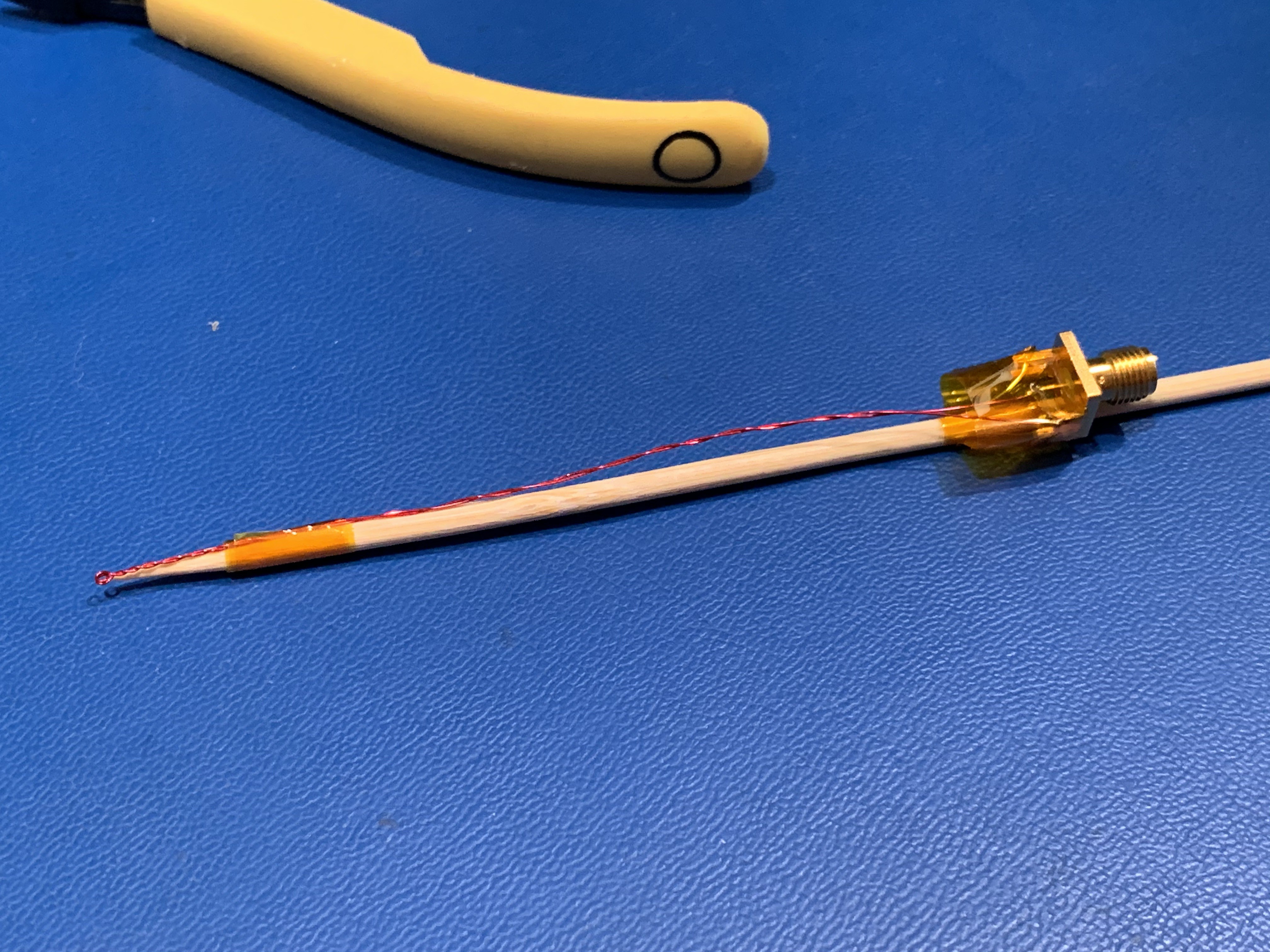
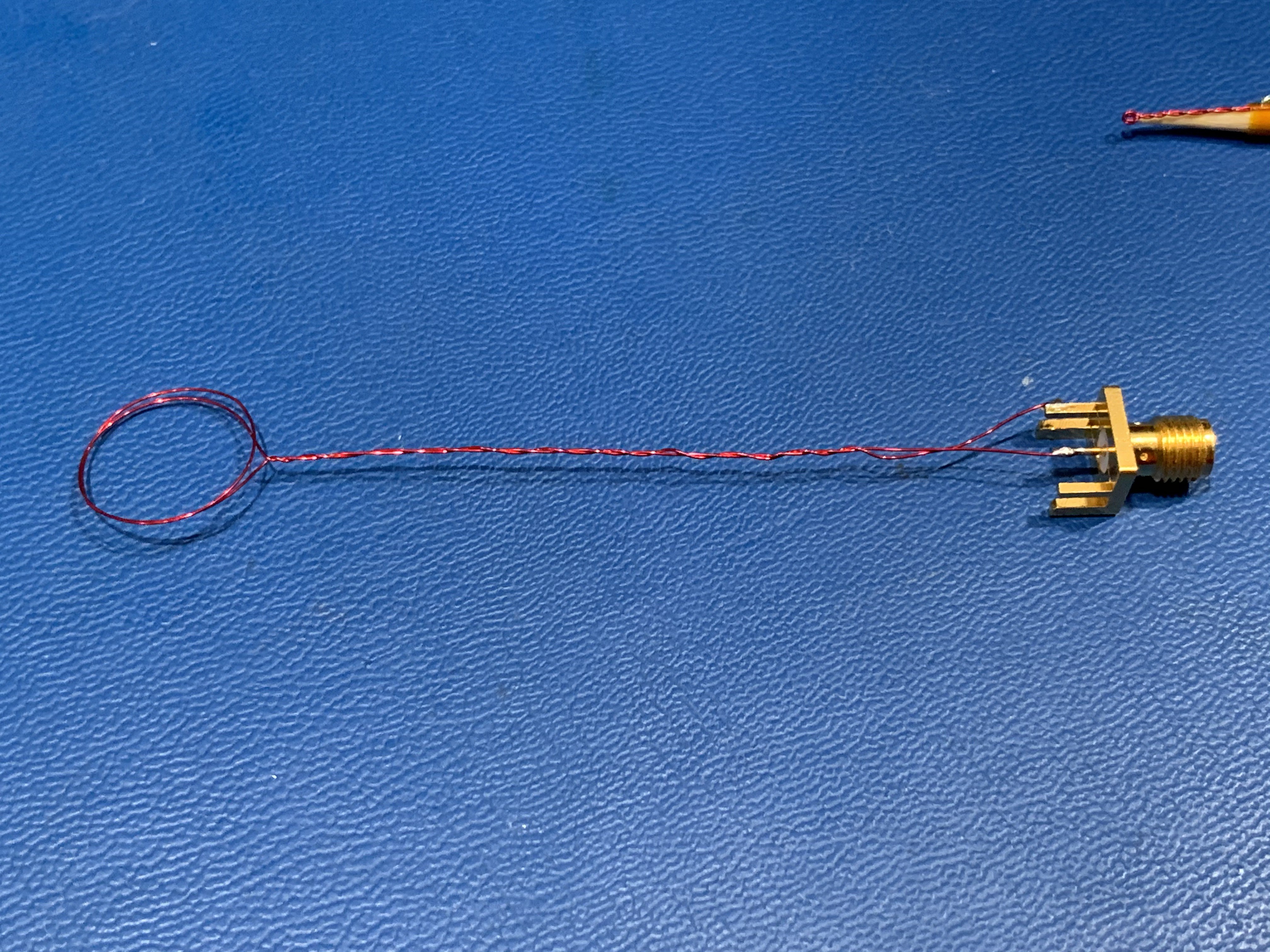
If you build only one probe for this workshop, it should look like this:
![]()
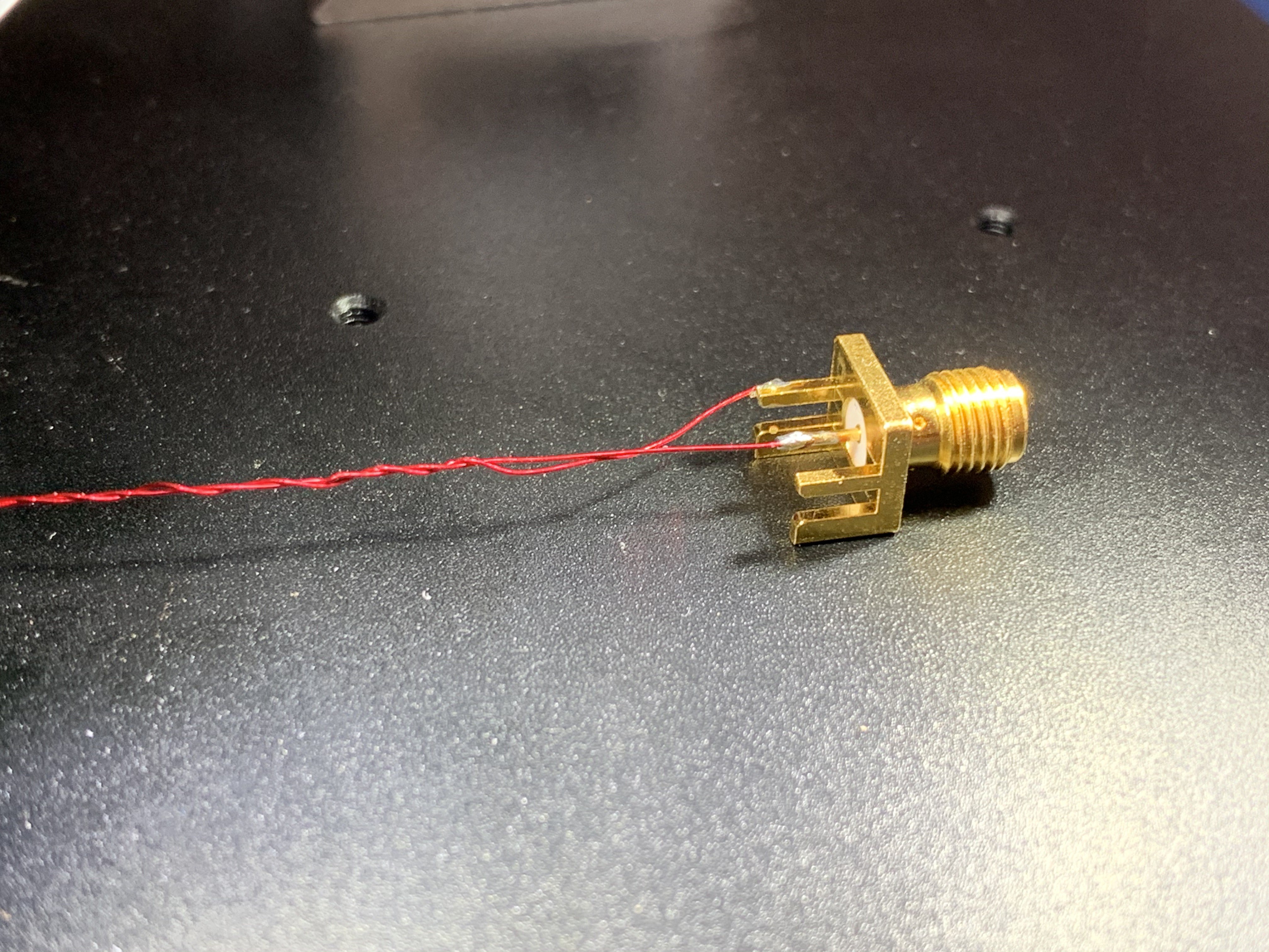
It's basically one full turn (so, technically two turns) of fine-gauge enameled magnet wire (in my case, 30 gauge), soldered to an SMA connector to attach to our SDR. Obviously, ultra-fine magnet wire is pretty floppy, so I taped mine to a wooden skewer for stiffness and handling. Anything non-metallic and insulating will do just fine. I intended to build a plastic version by dipping my probe in 3D printer resin and curing over and over, like a candle, but didn't get around to it.
The trickiest part is getting an ultra-fine loop on the end of the probe, which will result in very low sensitivity but extreme spatial resolution. We'll overcome the sensitivity issue with the LNA in our SDR signal path (see a later instructions post), and the resolution will give us single-trace accuracy looking for offending signals.
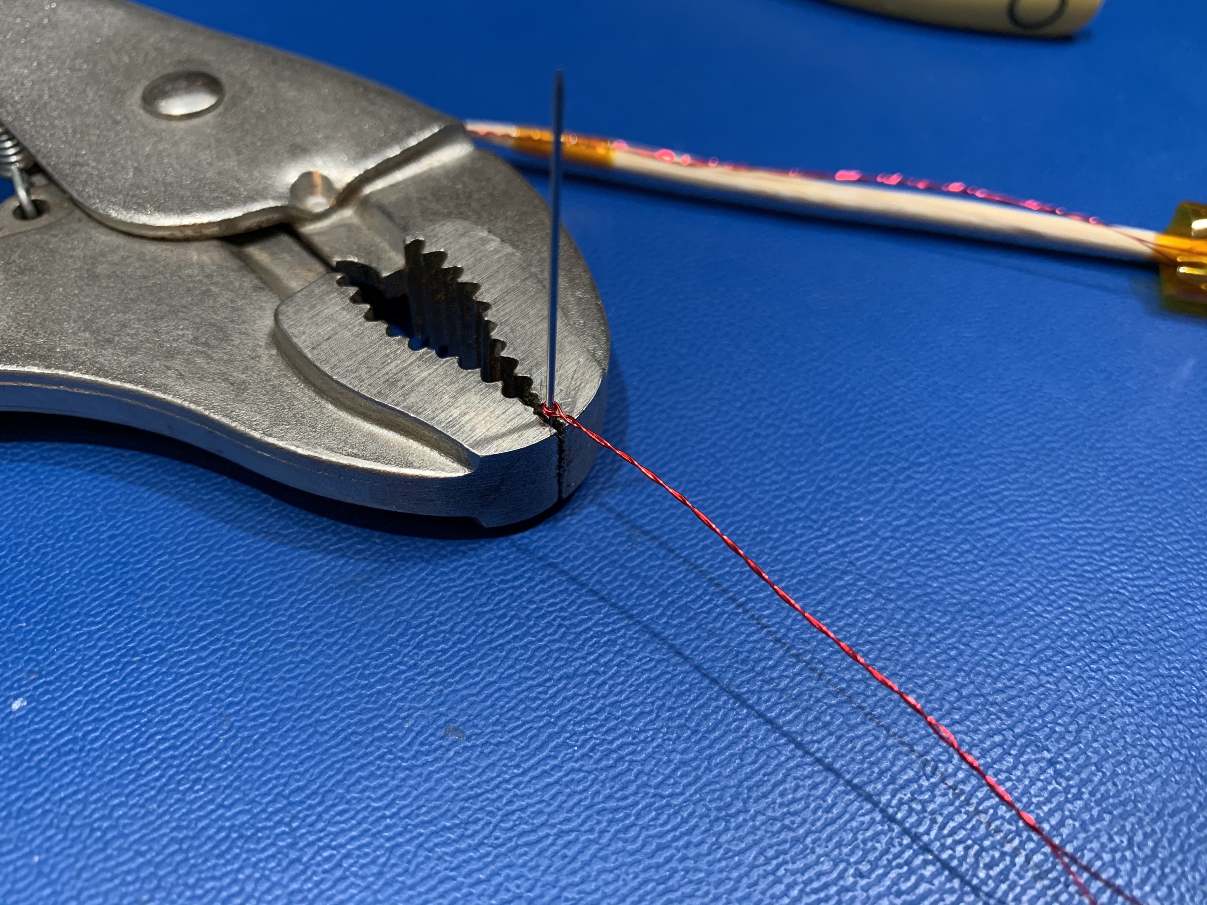
To make mine, I used a sewing needle as a mandrel, though any similarly-fine wire should do. I imagine solid-core 22ga wire would work, if you're careful. Or a clipped LED lead, even better.
![]()
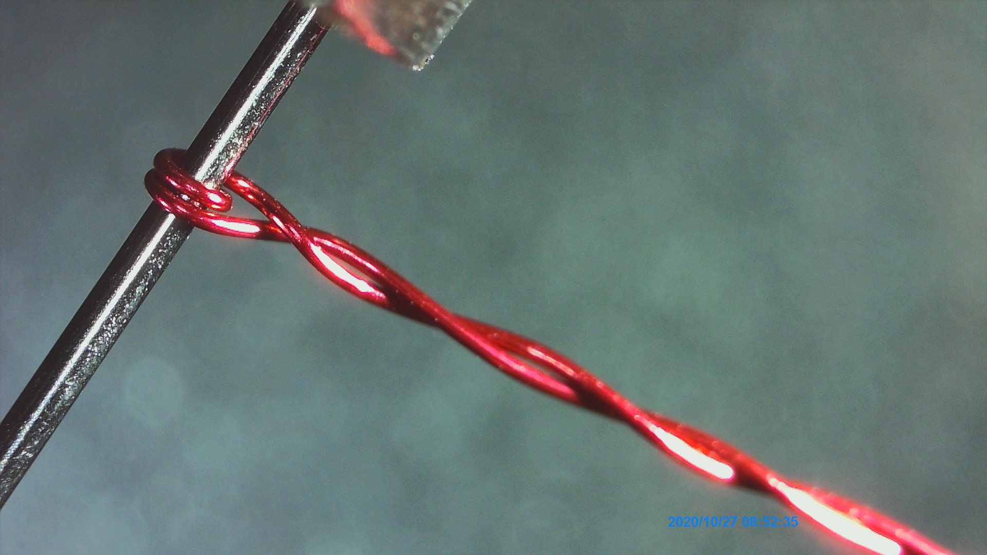
This is what it looks like up close:
With the loop made, twist the wires around each other as shown. The loop itself is SUPPOSED to be open, to "capture" the magnetic flux from your circuit like a net skimming a pool. On the other hand, since we ONLY want to know about the flux inside that little loop, we want to EXCLUDE any flux along the length of the handle wire. Twisting accomplishes that by 1) minimizing the area of any given loop, since the wires are very close to each other, and 2) flipping the polarity of adjacent loops. If the first parasitic loop has positive polarity with respect to the magnetic field, the second one will have negative polarity, cancelling any field that goes through both. It's a bit like building a transformer where half the secondary is wound one way, and the other half is wound the other way: you'd always get zero volts out. Actually, it's literally exactly that.
Finally, solder on the SMA connector. Polarity doesn't matter, since we're only interested in amplitude of an AC signal.
![]()
Ok FINALLY FINALLY, attach the skewer or whatever other handle you come up with.
Bonus: Building the "Medium" probe
I told you that you only NEED this super fine probe for the workshop, but there's a little more to see if you have a range of probes. I built this other probe exactly the same way as the one above, but using a "AA" battery as a mandrel instead of a sewing needle. I encourage you to do the same, and if you've got extra SMA connectors, build a few of different sizes. Bigger than 2cm isn't super useful, and much smaller than what we built above might not be either, so probably stick inside that range.
![]()
-
2Setting up your workbench
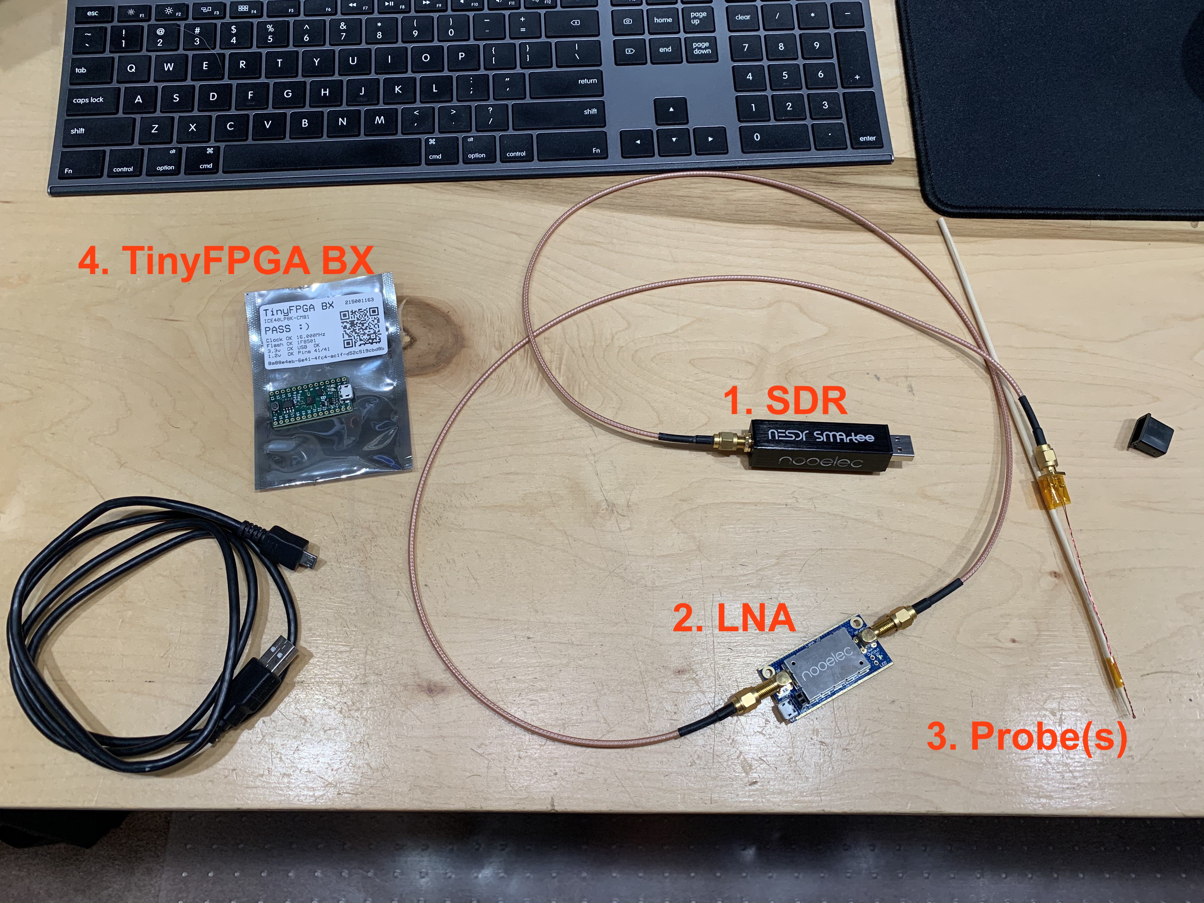
Before we start the workshop, this is what your workbench should look like:
![]()
1. SDR
I selected the Nooelec NESDR SMArtee for a couple reasons: 1) the RTL-SDR system is widely-supported and easy to use 2) it's as cheap as SDR gets 3) the SMArtee has a bias tee built in to power our specific LNA without any external shopping list items.
The critical pieces here, if you don't have the same SDR, are that it can receive as low as 50MHz (our signal of interest), and that you have a tool chain set up to actually run it (since this is the absolute hardest part of ANY SDR activity).
2. LNA
The Low Noise Amplifier is a critical component of our signal chain because the probes we're using are extremely low-impedance and low-sensitivity. The biggest issue with amplifiers in general is that they tend not to be perfectly flat across their whole frequency range, and therefore they introduce substantial measurement error. Luckily, in our case, we don't really care about that, since we're not trying to measure absolute signal strength. We JUST need to boost the microscopic signal up to the point where we can see it with the SDR, so that we know where it's coming from on the board by virtue of where our probe is when it shows up.
I chose the Nooelec LaNA again because it happens to play nicely with the SMArtee. LNAs are basically just common emitter amplifiers powered by a DC offset on their output. Since the entire RF signal chain is AC, you can isolate DC offsets anywhere you like by simply adding a series capacitor. Many LNAs have such caps on their output so they must be powered by some alternative source. The LaNA does not, AND it has a very low supply voltage requirement that's satisfied by the SMArtee's relatively low 4.5V bias voltage.
In theory, the gain of the LaNA here is a bit lower than you can get with some cheaper DC-powered LNAs (that I use and like), but in practice I didn't actually notice a large difference. Either is definitely sufficient for our workshop.
Important LNA/bias tee notes
There are a couple important things here.
1) Our low-impedance probe looks like a short at DC
2) Our SMArtee SDR has a 4.5V DC bias on the input that can't be disabled
3) Our LaNA is nearly bulletproof
The SMArtee puts out 4.5V dc, and while it has short-circuit protection, you should NOT short it for very long. That is to say, while it's tempting to try the setup WITHOUT the LNA just to see whether the signals are still detectable, you should not do this with this particular SDR, unless you have a DC blocking capacitor between the antenna and the SDR. You can do this with E-field probes, which aren't electrical shorts at DC, but not our naive H probes.
On the other hand, the LaNA is surprisingly robust. Given that it's compatible with powering via both bias tee and DC input, you might worry like me that using both at once would be a big no, shorting the DC supply to the RF output. Not so. The LaNA has a lot going on inside, including power isolation so that you can use external power even with a receiver that has permanently-on bias tee.
Now, you shouldn't NEED to do this if you're using the setup above, but in my case it was useful for switching between two SDRs for comparison, one of which didn't have a bias tee, while powering the LaNA from USB the entire time.
Anyway, long story short, don't connect our H probe to the SDR without the LNA in between.
3. Probes
There's not much to say here if you read the previous instruction step where we built the probes, other than the more the merrier. I'll personally be demoing two sets on top of the ones we built, including the RF Explorer budget probes, and the Rhode & Schwarz HZ-15 not-at-all-budget probes a client of mine happens to be renting right now. Luckily, it turns out, there's virtually no difference in performance, only build quality.
4. TinyFPGA Bx (And Micro-USB cable!) (And other boards!)
Lastly, we have to have something to measure. I've chosen the TinyFPGA Bx to be our device under test (DUT), because it's the cheapest way I know of to generate 50MHz noise on a programmable pin. However, I strongly encourage you to show up to the workshop with some other boards you might have laying around! The TinyFPGA is useful here because it gives us all a common reference to work on, but when you get in close to any board, it'll have all sorts of noise to explore. Grab an Arduino Uno and see if you can measure harmonics of the 16MHz crystal (16 is too low for the RTL-SDR, but 32 isn't). Or maybe an ARM arduino will show you its core clock around the chip.
The technique we'll be focused on depends on knowing what signal we're looking for first, and trying to figure out what's making it. But with patience, this can be done in reverse as well, looking for a signal we suspect might exist, or using a large probe to look across the entire spectrum at once farther away from the board. Making your own educated guesses and confirming them with a unknown DUT, like "I see a crystal, I bet I'll see X MHz noise" is just as educational!
-
3Setting up the software
We'll need two main software toolchains to get up and running: one for the SDR, and one for the TinyFPGA.
Setting up the SDR software
On the SDR side, we'll be using a couple of utilities: QSpectrumAnalyzer (https://github.com/xmikos/qspectrumanalyzer) and SDRAngel (https://github.com/f4exb/sdrangel)
QSpectrumAnalyzer is great because it lets us use our SDR like a traditional swept spectrum analyzer, capturing very wide bandwidth in a single sample. The disadvantage is that such a capture takes a long time, so there's a good chance that your signal of interest doesn't happen to be loud or "on" when the analyzer is sweeping that part of the range. The advantage is that you can see EVERYTHING all at once, rather than manually tuning this 2MHz range, then that 2MHz, then the next, and so on.
SDRAngel is useful because, for a frequency range narrower than the real-time bandwidth of your SDR device, SDRAngel has a view very closely approximating a real-time spectrum analyzer (RSA). Luckily, I have one of those on hand to show you a comparison. With the very limited bandwidth of the RTL-SDR, this is pretty limiting in terms of what we can accomplish, but it offers a lot of information in one view when analyzing a signal whose frequency we already know.
Like I said before, setting up SDR software is very much, in my experience, the most painful part of the technology. If your computer is at all capable, I STRONGLY encourage you to download VirtualBox and set up DragonOS, which is a project to build an out-of-the-box SDR environment with broad hardware and preinstalled software support, with minimum configuration hassle. It comes in a couple flavors including "DragonOS Focal" (https://sourceforge.net/projects/dragonos-focal/) which seems to be the most recent development, and "DragonOS LTS" (https://sourceforge.net/projects/dragonos-lts/) which is what I've personally used. There are also a lot of videos on YouTube made by the creator demoing various devices and software, to give you an idea of how to pilot many of those combinations, which I've found super useful.
Long story short, if you can download and install DragonOS (I'll personally test Focal ASAP), connect your SDR to it, and get a spectrum to show up in QSpectrumAnalyzer and SDRAngel, you're in good shape for the workshop.
If your machine isn't quite powerful enough to run a VM, you CAN install both programs on your native OS. I encourage you to get started trying ASAP.
Setting up the TinyFPGA toolchain
Follow this guide to set up the TinyFPGA toolchain with the Atom editor: https://tinyfpga.com/bx/guide.html
If you can flash the test program and make your LED blink, that's a great start!
I'll try to have the ACTUAL workshop firmware and flashing instructions ASAP :)
Remoticon: Basics of RF Emissions Debugging
RF is black magic and we're going to learn about it here!
 Lutetium
Discussions
Become a Hackaday.io Member
Create an account to leave a comment. Already have an account? Log In.
I have a TinyFPGA Bx purchased from Arrow. I can't get the toolchain to work. Atom won't program the board.
The error:
Activate bootloader by pressing the reset button
Error: board TinyFPGA-BX not connected
Are you sure? yes | no
@Shirley Márquez Dúlcey I had the same issue. I don't have a fix for atom but navigating to the relevant folder in a command line terminal (I'm Win 10) and using the `tinyprog -p hardware.bin` command managed to upload the blink example (which I had to press Build in Atom so that an actual `hardware.bin` was generated). It seems like it's doing nothing for 5 - 10 minutes on my machine and then suddenly it is programmed. I don't know if that's going to make the workshop difficult, due to the delay in programming but it's a start.
Are you sure? yes | no
Hi Shirley,
just had a problem similar to yours, and could get it disappear by updating the bootloader on the TinyFPGA:
tinyprog --update-bootloader
Are you sure? yes | no
I eventually got things to work by using a different USB port on my computer.
Still haven't gotten my RTL dongle to work in DragonOS in the VirtualBox VM, though. I'm going to try it out with a Live USB boot and see if that works.
Are you sure? yes | no
Did you manage to find the dongle with lsusb in dragonOS? I hadn't used a vm before so I had issues too. I added the RTL sdr in the USB filters and also the "on the fly" method mentioned here https://forums.virtualbox.org/viewtopic.php?f=35&t=82639#p390399
Are you sure? yes | no
@Shirley Márquez Dúlcey , UPDATE: I thought I had been through the bootloader update process but it appears I hadn't. Doing so fixed the apio issue and after restarting my PC, the speed of programming is now only a few seconds, rather than 10 minutes. To find your bootloader version in the command line (assuming you can see the tinyfpga as a COM port in device manager) having installed tinyprog, type `tinyprog -m` and you should see something like (after maybe several patient minutes of waiting): {“boardmeta”: {“name”: “TinyFPGA BX”,“fpga”: “ice40lp8k-cm81”,“hver”: “1.0.0”,“uuid”: “75e4e04a-1666-4789-b276-8309fa2d09ed”},“bootmeta”: {“bootloader”: “TinyFPGA USB Bootloader”,“bver”: “1.0.1”,“update”: “https://tinyfpga.com/update/tinyfpga-bx 4”,“addrmap”: {“bootloader”: “0x000a0-0x28000”,“userimage”: “0x28000-0x50000”,“userdata”: “0x50000-0x100000”}},“port”: “COM4”
bver is the version - it needs to be 1.0.1 to work with apio. To initiate an update, type `tinyprog --update-bootloader`
More info here: https://discourse.tinyfpga.com/t/error-board-tinyfpga-bx-not-connected-solved/383/44
Are you sure? yes | no
Ahh my apologies I didn't see this in a more timely fashion! The TinyFPGA is necessary for the sake of loading a demo firmware that spins up PLLs to crank out loud interference frequencies in the >25MHz range where we can measure them with the SDR. If you have a xilinx board and know how to use it, all you need to do to follow along with us is to synthesize a PLL block and wire a high-frequency clock straight to an output pin. My demo firmware runs 50MHz into the onboard LED since that's the kind of thing you might somehow accidentally do, and it's a huge noisemaker.
That said, it is plenty educational to wave the magic RF wand over any old board and see what/if they're radiating. An FPGA board is a good bet since it'll have a potentially-fast-enough oscillator on board. I need to try a few different off the shelf dev boards to see if I can find any obvious test signals to direct people to, but they're a bit harder. For instance, the Arduino Uno has a 16MHz oscillator, which you can definitely measure with our techniques but NOT with the specified RTL-SDR. You'd need something like a HackRF that goes down to 1MHz, or you'd need an upconverter and to know how to use it.
Long story short: if you can't find a TinyFPGA anymore, bring whatever boards you have and can easily power up, and I'm sure we can find something fun on them!
Are you sure? yes | no
@opprud PCBway has a "gift shop" (similar to FF mile gift shops) that you can redeem with points or dollars. As of this writing, they still have the BX in stock if you decide you really want one.
Are you sure? yes | no
The TinyFPGA was sold out. Can you post a bit about what's supposed to be build in the FPGA, then it could be coded / synthesised for one of the Xilinx boards a have available, perhaps...
Are you sure? yes | no