The construction and software files contain the complete information for building the project.
Ground Penetrating Radar using Arduino
To make the experience fit your profile, pick a username and tell us what interests you.
We found and based on your interests.
The construction and software files contain the complete information for building the project.
Operation_Instructions.txtOperation instructionsplain - 2.48 kB - 08/02/2026 at 08:35 |
|
|
Software.zipArduino and PC (in LabVIEW 2013) software source codex-zip-compressed - 917.42 kB - 08/02/2026 at 08:35 |
|
|
Antennas_v2.zipAntennas - New version of antennas, must be printed on double-sided PCB FR4 laminate size A4 (210 x 297 mm). PDF for Toner Transfer construction (Top layer mirrored) and GERBER filesx-zip-compressed - 70.87 kB - 05/15/2024 at 11:54 |
|
|
PCB_Construction_Toner-Transfer_Method.zipPCB images in PDF for Toner Transfer PCB construction (Top layer mirrored), and schematicsx-zip-compressed - 1.93 MB - 08/27/2025 at 09:16 |
|
|
LF(GPR_LF).zipOrCAD 9.2 design files and Gerber for Low Frequency boardx-zip-compressed - 159.42 kB - 06/07/2025 at 18:40 |
|

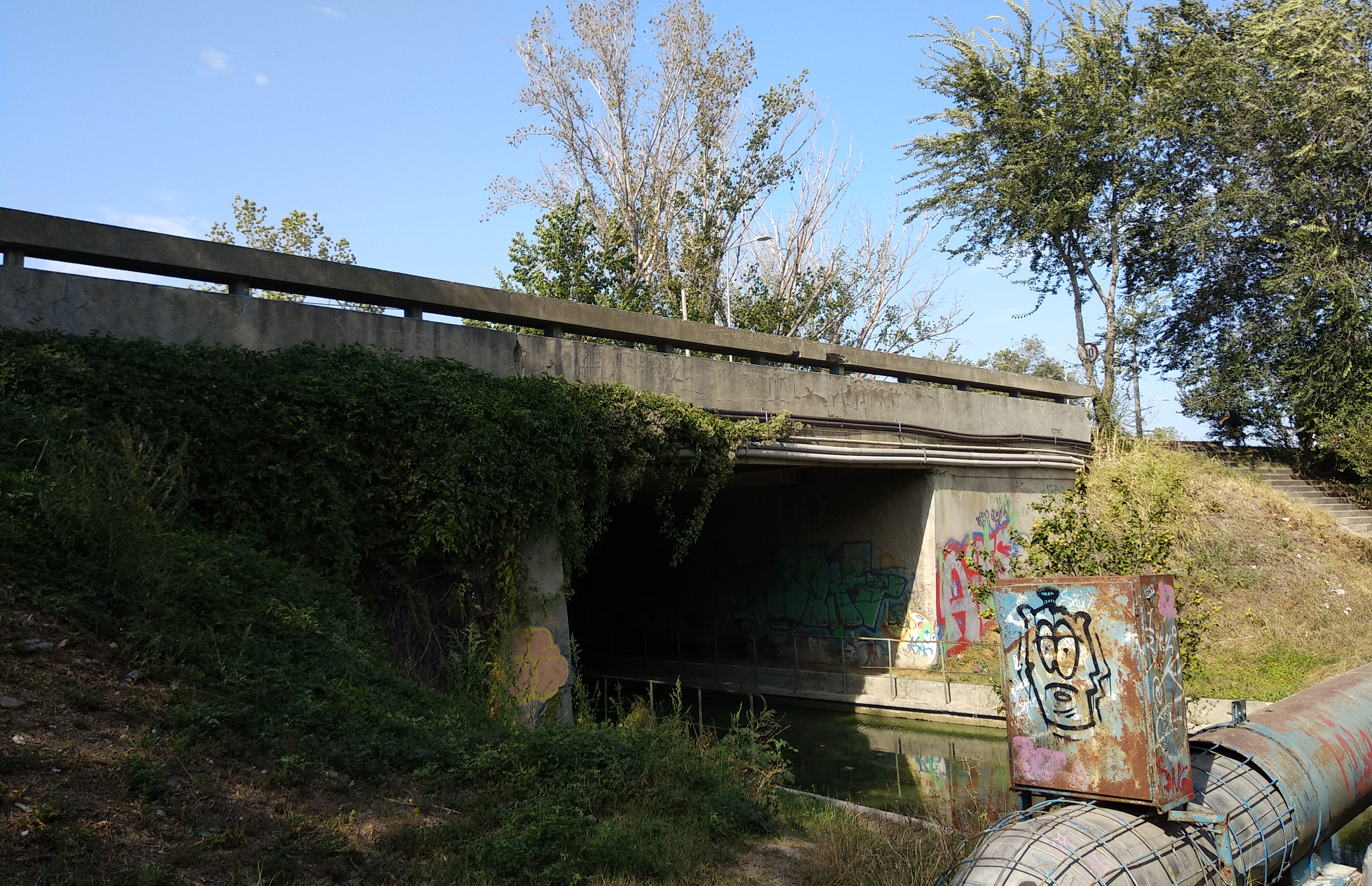
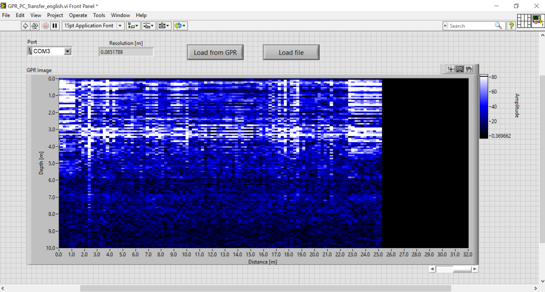
System tested on a bridge. This is the GPR image obtained for the bridge in the photo:
System tested and works fine.
Antenna coupling is quite high. Would be nice placing the antennas at a bigger distance from each other, or using more directive antennas in order to reduce unwanted coupling.
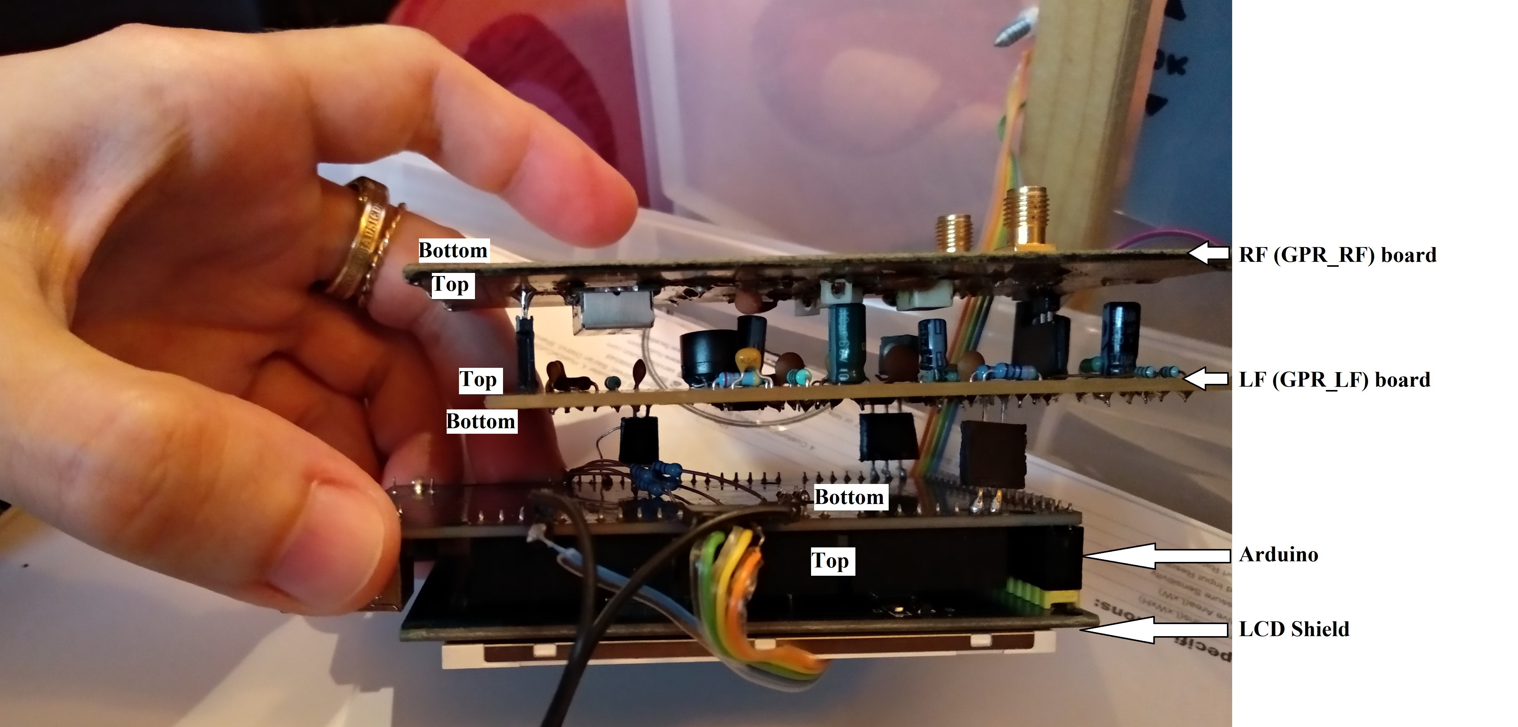
This is how the electronic boards are stacked.
Create an account to leave a comment. Already have an account? Log In.
It’s an interesting project congratulations @Mirel Paun . I was just wondering: almost all GPR devices use hyperbola-shaped reflections to identify objects, whereas your system seems to detect changes in another method. If you could display the results as hyperbolas, I think the objects would be easier to identify and trace.
I improved the code by using interpolation for displaying the image. Now it shows hyperbolas. It was a problem of resolution.
thanx, which one do you update labview one, debug python one or the arduino gpr wheel one.
what about the installer in https://drive.google.com/file/d/1fTImNGTH--9QTrTLh3JD8akViHZg7n2P/view?usp=sharing
It installs the last version of the PC program, it's made from the source code (.vi) that I placed here.
@Mirel Paun Good day, I did test on my room floor (concrete under it there is another room which is the ground floor final one there is no payment) I got this, the blue marks are for the areas that the GPRINO was not moving since I am using no wheel mode. I did use python debug and use the extrcated txt in the R RGPR library. https://myimgs.org/storage/images/26249/rada_image.png
Try the last programs (Arduino code and PC).
Also, in order to improve the directivity of the antennas and also provide some shielding to ambiental interferences you can place a conductive plate 45x45 cm at 15 cm behind the antennas, at 90 degrees (perpendicular).
In this test I did already put the antennas each one in card box and cover it expect the bottom with aluminum foil (top from antennas around 12cm). I tried to use your debug python to start to behave unnormal after the first window finished, so I did one using AI (did take your last codes for arduino and python and explain the issue then I extrcated those in the link). here are the links for both. kindly lead me I guess I am kind of lost here,
https://limewire.com/d/QnwDd#qDqKwukhFA
Even for R with the orgianl debug python and arduino code you can't run this
library(RGPR)
x <- readGPR(dsn = "D:/test.txt")
x1 <- gain(x, type ="exp", alpha = 0.01347, t0 = 0, te = 110)
plot(x1, col = palGPR("grey2"))
it will throw errors such as
p1 <- RGPR::gain(p, type ="exp", alpha = 0.01347, t0 = 2, te = 110)
Error in if (caller %in% c("convertTimeToDepth")) { :
the condition has length > 1
The problem is in the python code, more exactly the very slow update speed of the image which makes the program lose data. The arduino codes are OK.
I corrected the python code by using a different plotting approach so that it updates only the image and not also the axis. Now it works OK, also with RGPR. Try it, it's in the GitHub repository, GPR.py.
I did test with wheel after you made the last edits on the GPR.py and I did draw the extracted file with RGPR and I got the image
https://myimgs.org/storage/images/26738/Screenshot2026-08-08162907.png
The test: I did scan my room floor. There is another floor under me, there is an attic, I guess it is about 2m, and it is right after my room's concrete floor. There is a bathroom under it then the floor of the floor under me, in this floor, after about 7 meters in my scan, where I got some of the white area. Can you help me to evalute this image and to determine if I have any issues in my GPRino.
Here are some images of my menus and graph. I am using a different screen than yours which dictated some coding changes. The last picture is from a quick sweep inside my house which has a concrete slab for the foundation. I do not know whats under there, so I cannot confirm whether or not the data is good.
https://myimgs.org/storage/images/22424/IMG_1635.jpeg
https://myimgs.org/storage/images/22443/Menu-2.jpeg
https://myimgs.org/storage/images/22444/Menu-3.jpeg
https://myimgs.org/storage/images/22445/Graph Blank.jpeg
https://myimgs.org/storage/images/22446/Graph full.jpeg
Yes, it would be useful to test it in a known, controlled scenario, like on top of a tunnel or over a pipe to see how the displayed image correlates to the underground.
https://myimgs.org/storage/images/22271/GPR_LF_Stackup-2.jpeg
https://myimgs.org/storage/images/22272/GPR_Set-02.jpeg
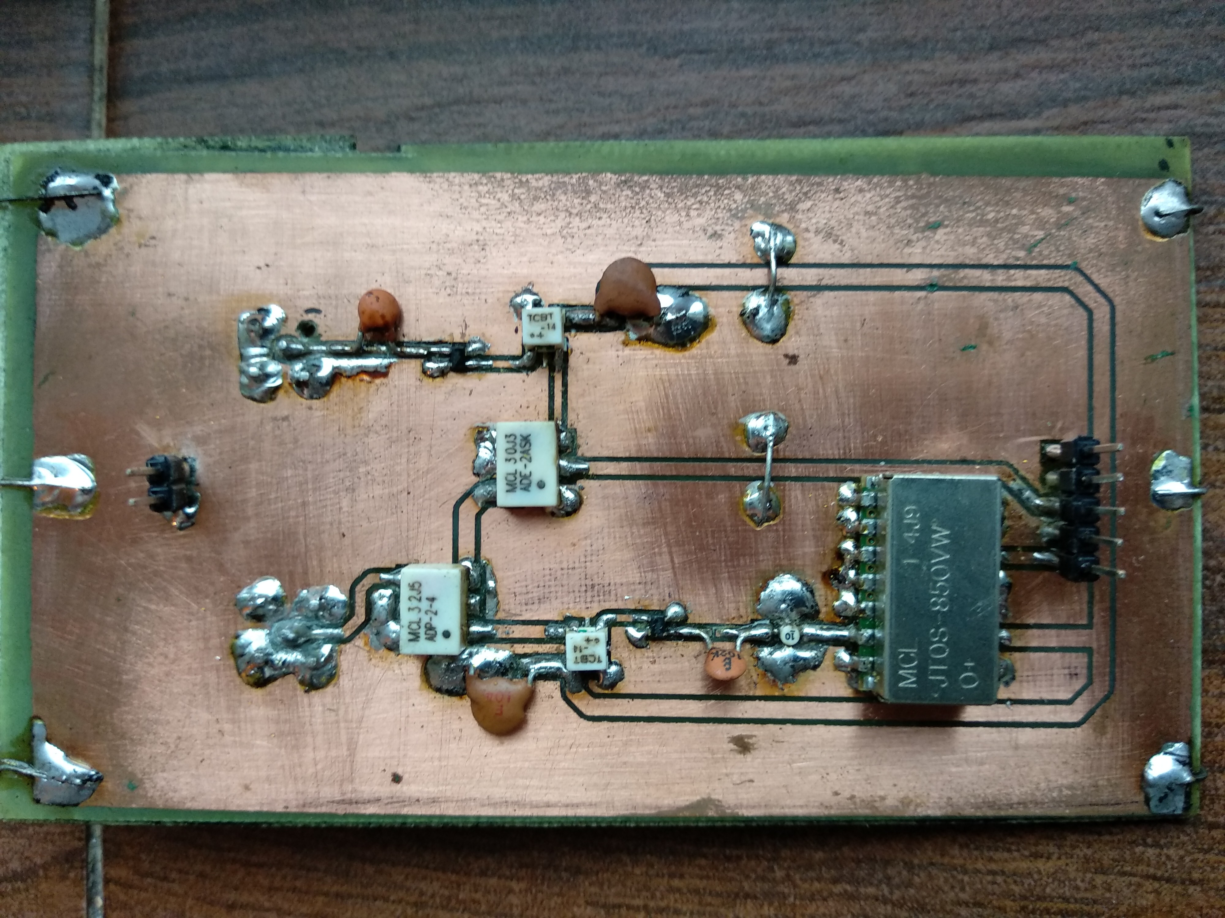
https://myimgs.org/storage/images/22273/GPR_RF_Inside-1.jpeg
https://myimgs.org/storage/images/22274/GPR_Antenna-1.jpeg
https://myimgs.org/storage/images/22275/GPR_LF_Connection-2.jpeg
https://myimgs.org/storage/images/22276/GPR_LF-RF_Connections.jpeg
Hello! Your boards look impressive. I would love to see some scan results. I'm very curious to see how the RF shielding improves scan quality. Did you use the Arduino code that compensates the VCO nonlinearity?
Thanks! I am still working out the antenna height and sample rate. I do believe the shielding has helped, but I don't have definitive evidence at this point.
As for the code, I had to do quite a bit of modifying to use a different LCD, mainly menu issues and graph layout. I believe I am using the latest code you've posted here for all the calculations. I will add a few more pictures to the above thread to show my screen after a sweep over concrete.
My weakness is coding, and I don't have a full grasp on everything you did, so i am reluctant to make too many changes. I would be very interested in supplying you with a set of boards in trade for some help working out the bugs. I have several extra LF & RF blank boards, but I currently only have one extra antenna. I can get more made, but the antenna's were the expensive part. I'll set you up with what I have for some help if you're interested. And I will try to keep all results posted here for others to enjoy as well.
Is this the section of code you are referring to?
//modulator signal ramp that compensates JTOS-850VW+ nonlinearity
const word modulator_sig[256] = {
I updated all the programs right now. The displayed image should now be improved by the interpolation I implemented.
https://myimgs.org/storage/images/21998/GPR SHIELD BLK.jpg
https://myimgs.org/storage/images/21999/GPR RF BLK.jpg
I have been working on further development of this and have produced a few Arduino Shield style LF boards and a shielded RF board with proper ground plains, etc. I also adapted the firmware to accept a more readily available LCD screen that mounts to the Arduino 2560 boards. I would be interested in working with this group to refine the setup of the mobile rig if anyone is interested. I will try to post a few pictures as time allows.
I’ve been working on building one of these and have the arduino, display, RF, and LF board stack completed, tested, and functioning. But for the antennas, there are 2 gerbers for the top and bottom, so do those go on each side of the same board, or is each layer a separate antenna? And the drawing seems to suggest that they should be separated by 100cm, but that’s not what the pictures show.
Hello,
Thank you for designing this project. I tried to make the cards by buying the PCB on JLCPCB but some layers are reversed. This is probably due to an export error from Orcad.
Can you provide the design in ODB++ format please ?
Hello, I couldnot find .opj file for the RF? Could you please upload. Would really appreciate
hi can anyone give an approximate estimate of depth penetration in soil ?
Good evening, I noticed in the diagram the components LMV772 and MCP4725, in the photos the 772 has 6 pins but they only exist at 8 pins.. while the MCP4725 has 8 pins in the photo but I can only find them at 6 pins.. what was mounted on the card instead of the ones in the diagram? can someone help me? what did you mount on the card? do you have any alternatives for me? Thank you.
Hello everyone, my name is Hamdallah, I am from Afghanistan, thank you for sharing your project
I have a problem in the uploading part of the program and an error during uploading. includ Arduino fft.h. I couldn't do anything with all my efforts
Hi , use the manage library command , search for fft then add arduinofft, Use 1.62 I think as the latest errors out. I've just started looking at this [project,
Hello everyone, my name is Hamdallah, I am from Afghanistan, thank you for sharing your project
I have a problem in the uploading part of the program and an error during uploading. includ Arduino fft.h. I couldn't do anything with all my efforts
Hi,
What is the license of the project, I mean, could I reproduce it (or part) for educational and non commercial purposes?
BR,
Francisco
Can anyone please tell me the purpose of the GPR_JF board?? What does it do??
Hello. Can you post all the documentation of this GPR project? I need inter-board connection project.
thanks.
aksuerdogan79@gmail.com
Hello. Can you post all the documentation of this GPR project? I need inter-board connection project.
thanks.
hi i am doing this project and i am stuck with antenna part , idk how to do it! if anyone can help that will be amazing.
Hi , I would like buy also all the project from you ?
Become a member to follow this project and never miss any updates
CiferTech
Abid Jamal
Embedotronics
Really good to see more action here on this project, it IS very worthwhile. I have a few questions that I haven't really seen answered yet.
1 - How far off the ground should the bottom of each antenna be?
2 - What is the best distance between pings? Mine is currently set to ping every 55cm (2.25"), should it be farther apart or closer together?
3 - Is the white area indicating an object or the dark area?
4 - Should I expect the image to be returned when the unit is closer to the send antenna or the return antenna and which antenna should lead and which should follow?