You can see how it works in this video
MCU
Main microcontroller is a mainstream STM32f070 32-bit ARM Cortex-M0, operating at 48MHz, with 32Kb of FLASH memory and 6Kb of RAM.
The embedded firmware uses three different peripherals from the micro:
- 12bit ADC to read the sound signal in continuous mode.
- TIMER configured to work at 800KHz to send PWM signal to the LEDs with the NRZ protocol.
- DMA, used for the ADC acquisition and to send data to the timer channel as a PWM signal, so the CPU is unloaded as much as possible during all the process.
Sound acquisition
it uses an omnidirectional electret microphone of 6x2,7mm with -50dB sensitivity working at frequencies from 100Hz to 10KHz. Signal is amplified with an op-amp that features rail-to-rail input and output, with a 6MHz gain-bandwidth that can be adjusted with an SMD variable resistor.
LEDs
The LEDs are WS2812 chips in a 5050 package, and I use two different versions according to the needs of each project:
- WS2812B for a max brightness results, with an overall consumption of 380mA.
- WS2812C for a much long run on battery powered devices. Brightness is reduced to one-third of the B version, making overall consumption reduced to 180mA.
User Button
Button allows you to switch between different light patterns:
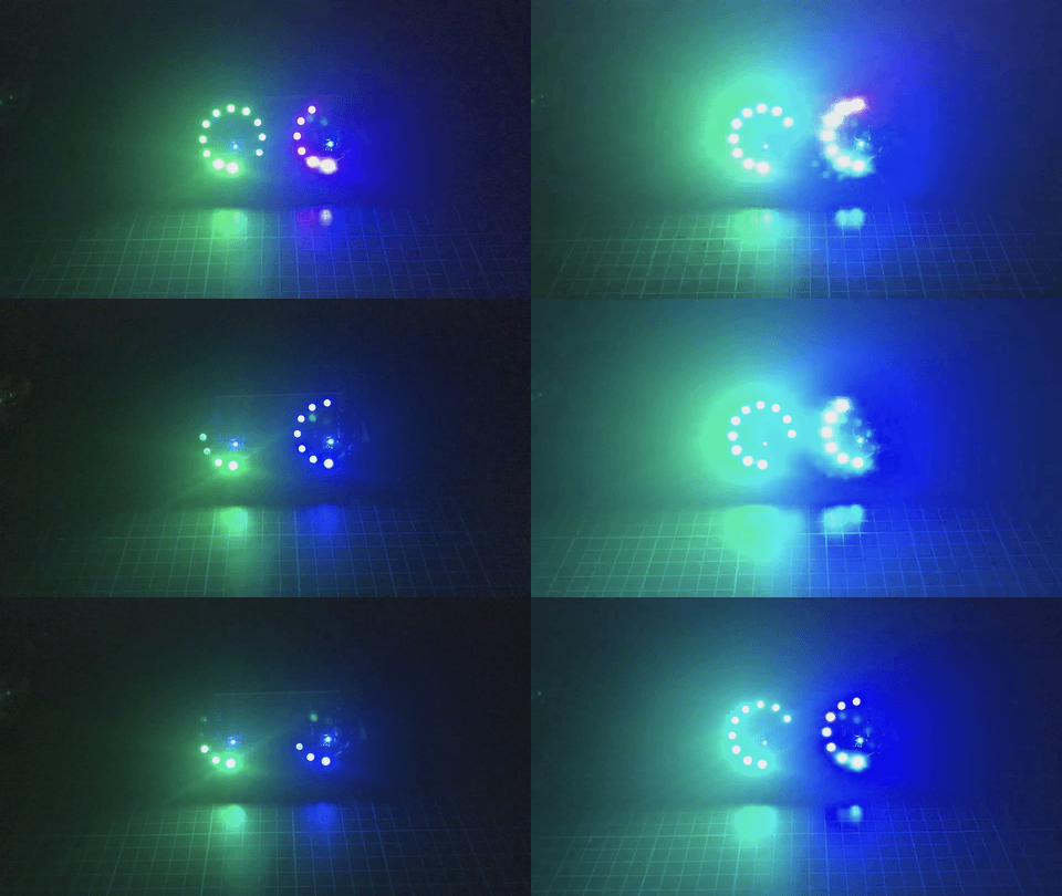
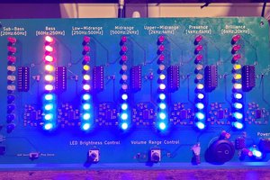
Sound pressure Gauge
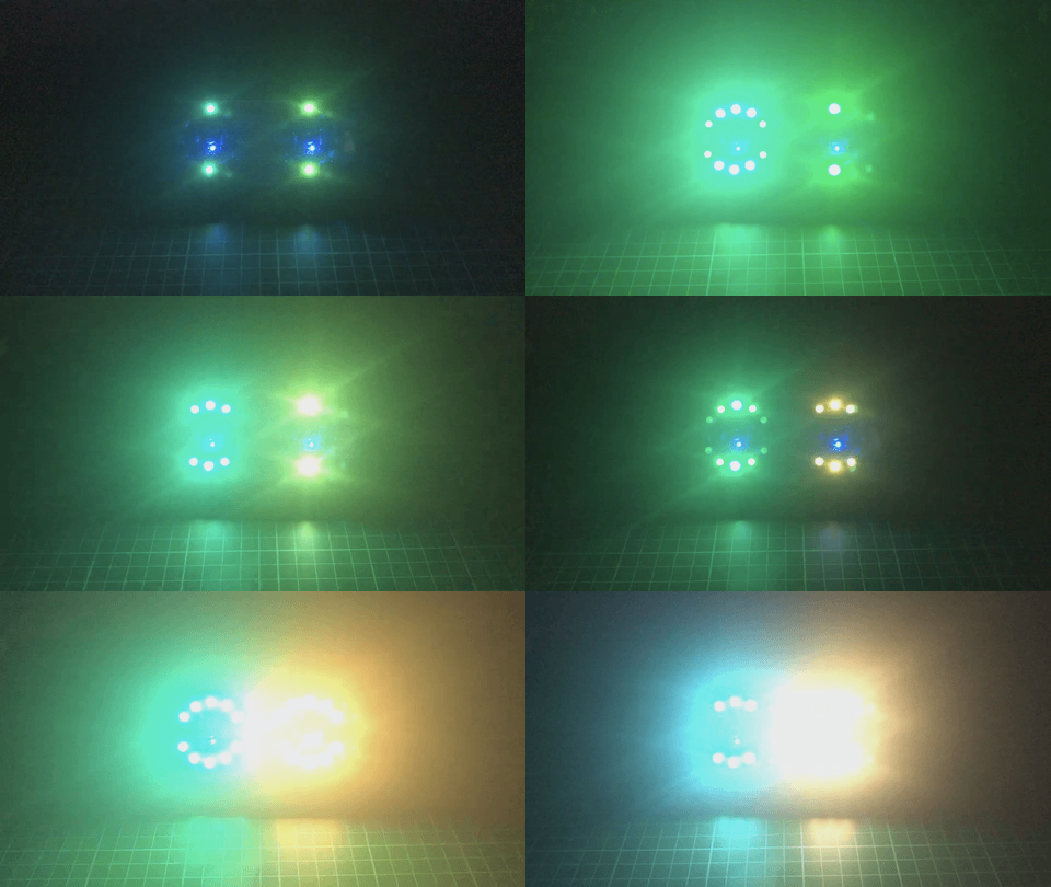
Half ring mirrored
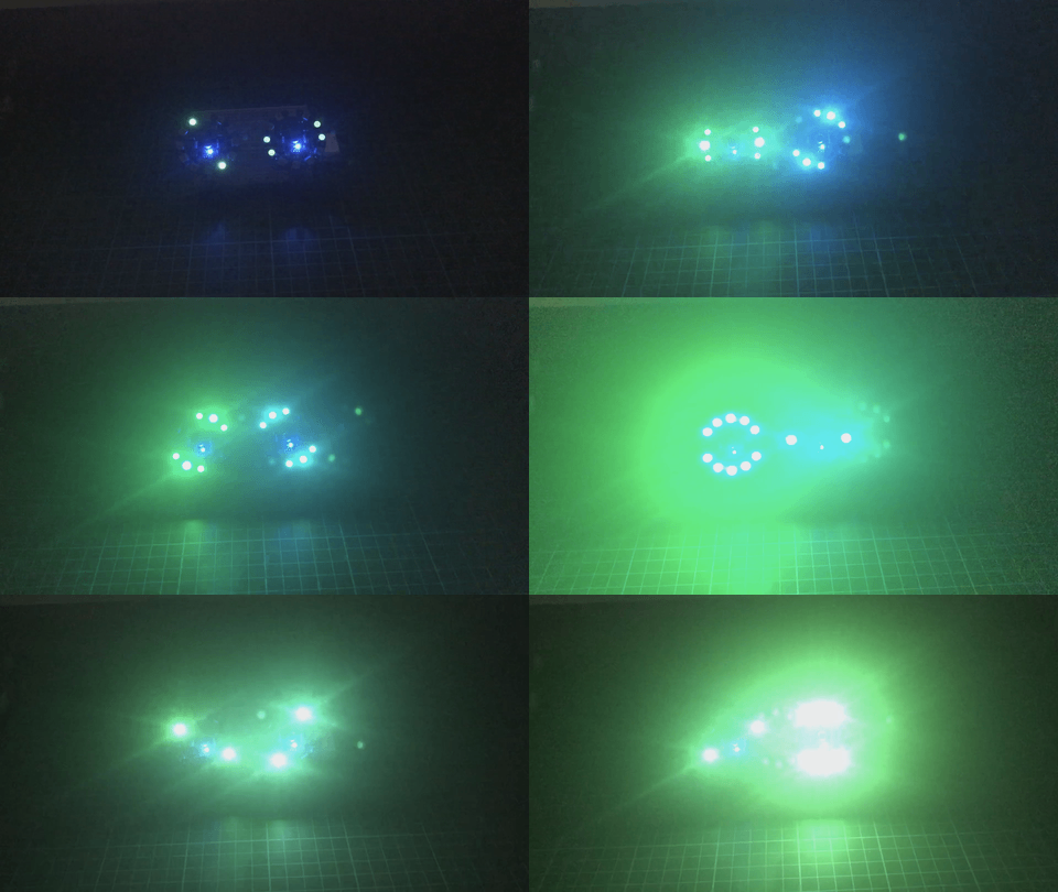
Half ring with rotation
With a hold-press, you can adjust the max brightness. Visit the github project page for more info.
Voltage ratings
There is a LDO voltage regulator to adjust input voltage to the 3.3V required by MCU. It accepts a max input voltage of 5.5V, but it must be down to a range of 3-4V for proper communication with LEDs, so a LiPo one-cell (1S) is a good option.
A Schottky diode protects the system from reverse polarity.
Connectors
The board exposes I2C pins to acquire data from external sensors, SWD pins for MCU programming / debugging, Audio OUT pin to access the op-amp output, and WS OUT pin to attach more LEDs to the system.
 Manuel Alfonso
 Jithin
 doctek
 Ghani Lawal